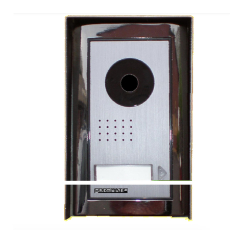
Forematic 500 Quick start guide

Page 1
500 VIDEO DOOR PHONE
Safety & Operating Instructions
Please read through these instructions thoroughly before use and retain for future reference.
- Contents -
1 User guide
1.1 Safety instructions Page. 1
1.2 Guide to the equipment Page. 2
1.3 Operating instructions Page. 2
2 Installation
2.1 Preparation & contents Page.
2.2 Cables required Page.
2.3 Installing the screen Page. 4
2.4 Installing the camera panel Page. 4
2.5 Completing the installation Page. 5
2.6 Commissioning Page. 6
3 Care and maintenance
3.1 Daily maintenance Page. 6
3.2 Warranty Page. 6
3.3 Trouble shooting Page. 7
Appendices
App.1 Wiring diagram Page. 8
App.2 Technical characteristics Page. 9
App.3 Equipment upgrades Page. 9
- 1.1 Safety Inst uctions -
This product is designed for moderate climates. Do not
use in high humidity, dusty, or dirty environments. The
camera panel should be mounted with its rain hood
away from pouring water. Never use a pressure washer
near the camera panel. Trim back vegetation around
the camera panel to avoid dripping and lens abrasion.
Facing extreme sunlight will reduce picture quality.
Screens should be wall mounted on the bracket
provided. Do not allow curtains or clothing to cover the
ventilation holes behind the screen. Do not allow the
screen to operate near steam, moisture, naked flames
or extreme heat as found in some kitchens areas or in
bathrooms. Avoid extremely bright locations which may
affect the screen image.
Never disassemble components. Do not overload
power sockets, and remove the power if the system is
not to be used for long periods. Do not drop or apply
physical shocks. Do not expose units to acid oxides,
ammonia, or any other harmful substances.
Some electrical goods such as microwave ovens, TVs,
computer equipment, large electric motors or radio
transmitters may interfere with the screen signals. Keep
a clear distance from these devices if interference is
experienced.
Doc.
QP
-
50
0
4 wire video
500, 505, 5 0
V1.2 english

Page 2
- 1.2 Guide to the equipment -
Sc een
- 1.3 Ope ating inst uctions -
1. Receiving a call
When the call button on the camera panel is pressed,
the screen ring tone sounds and the visitor’s image
appears on the screen. If you wish to talk with the
visitor, touch the button. The screen will stay on
for about 80 seconds before it automatically shuts off.
To re-activate for continued conversation, touch the
button and then touch the button.
2. Viewing the st eet f om monito unit
a) Touch the button of the indoor unit at any
time and the screen will show the outside view.
b) Viewing terminates automatically after 40 secs.
c) If you have two cameras, touch the button again
to change from camera one to another.
3. Wo king times
a) Call time: The screen rings for only 40 secs,
then the call is terminated.
b) Talk time: Conversations are limited to 80 secs.
Extend call by touching then button.
c) Viewing time: When activated from the screen,
viewing is limited to 40 seconds.
4. Inte com call
Intercom allows one screen to call the another if it is
installed. Touch to answer the other screen.
Touch to finish or the call will terminate in 80 secs.
5. Open the doo
Touch the button to unlock the door.
6. Change the ing tone
From standby mode, touch the button. The tone
will sound. Touch to choose a new ring tone from
4 available. Touch to confirm the new tone.
1. Monitor screen
2. Talk on / Talk off (Monitor off)
. Door Open
4. Camera 1 / Camera 2
5. Intercom
6. Menu Select (Brightness,Contrast,Colour)
7. Down
8. Up
9
Microphone
10. Ring tone volume
Came a panel
Camera lens
Night vision LEDs
Speaker
Name Plate
Call Button
Microphone

Page 3
- 2.1 P epa ation & contents -
Check the contents of the package.
- 2.2 Cables equi ed -
Only three cables are needed for the standard set
without an electric lock. Cabling to the electric lock
requires a further two cables. Electric gate control
panels need only one extra cable because there is no
lock supply.
The mains cable must be 240V rated, at least A
capacity. Though a 1 A socket is shown, the power
supply could be wired directly into a fused outlet. Only
competent persons are allowed to work in some areas.
All other cables are low voltage rated. The screen to
camera panel is the longest low voltage run and needs
four cores. The other runs tend to be shorter, so it is
expedient to use the same four core cable for these
runs too.
Cables may run outdoors. If they do, choose an
outdoor rated cable that is non-porous and resistant to
UV light. The cable specifications are printed in a
technical table in the appendix. Screened cables are
necessary in industrial environments, but seldom
needed in homes. Thin flexible cable is much easier to
connect into the camera panel and the screen.
Cat.5 is commonly available and inexpensive, but must
be used with care. The V wire must not be doubled up
or paired with any other used core. Cut its pair off at
each end of the cable. Uses a pair doubled up for the B
wire, and another pair doubled up for the G wire. The A
wire does not need doubling.
Mains Powe supply Sc een Came a panel Lock supply Lock
Pa ts Supplied
Ref Desc iption Illust ation Qty Ref Desc iption Illust ation Qty
A Indoor Monitor
1 E Power cover
1
B
Outdoor
Camera &
Rain Hood
1
F Locker
2
G Bracket
Holder
1
C Wall mounting
bracket
1 H Screw
10
D Power
Transformer
1 I 4 core wire
assembly
Optional

Page 4
- 2.3 Installing the sc een -
1. Cable unning
The cable needs to be run before the screen or camera
panel are mounted. Do not run the cables near large
electric motors, radio equipment which can radiate
interference, or environmental hazards such as fires.
Screened cables reduce interference where radiation
sources cannot be avoided.
2. 4 co e connecto
A pre-wired four core connector with short cables is
provided for the screen. An area is required behind the
screen to connect this wire assembly to the camera
cable. Silicon filled ‘jelly’ connectors are recommended.
A = Blue G = Black B = Red V = Yellow
3. Powe connecto
Connect the 2 core power cable from the power supply
to the green terminal block behind the screen. Be sure
to connect the correct way round or it may be damaged.
4. Fix the mounting plate
Place the mounting plate over the top of the connection
area, passing the wire assembly through the middle of
the plate. Secure with four appropriate screws.
5. Hang the sc een
Carefully place the screen on the four mounting bracket
hooks. Then gently push the screen upwards to engage
the hooks in the monitor’s slots. Secure with two the
screws provided
- 2.4 Installing the Came a Panel -
1. Cable unning
The cable needs to be run before the camera panel is
mounted. The recommended height for a camera is
1.6m to suit average height. The cable must emerge
from the wall 7cm below the camera height and 2cm to
the left.
If you are fitting an electric lock, or wiring to an electric
gate control box, there will be at least one extra wire.
2. Mounting the ain hood
Slide the rain hood over the wires. Mark the mounting
hole positions. Drill and fix the rain hood to the wall.
Take the face plate off the camera. Pass all the wires
through the back plate of the camera panel. Mark the
two mounting hole positions, central top and bottom.
Drill & fix the back plate to the wall inside the rain hood.
3. Connections
Follow the wiring diagram in the appendix. There is little
space under the camera cover to coil extra wire, yet
cutting cable exactly to length is a risk. We recommend
making connections to the panel, then to pull all excess
cable through the wall where it can be coiled neatly. Fix
the camera cover on after the cables are secure.

Page 5
- 2.5 Completing the Installation -
1. Placing the powe supply
Power supply modules should be mounted near to the
master screen. Modules fit into an electrical distribution
panel or fuse cupboard. Wire the 240V mains input to a
switchable source such as a mains socket or fused spur
2. Fitting an elect ic lock
Electric strikes connect to the camera panel on a two
core cable. Most strikes are for doors with spring load
latch bolts. Mortise and rim versions are available.
Locking magnets are a simple alternative to fit, but
need an additional timed relay to connect to this panel.
3. Connecting to a gate cont ol panel
The panel has a momentary volt free N/O contact that
is accepted by all gate and door control panels. A two
core cable is required from the camera panel to the
gate controller.
4. Fitting the name plate
Remove the name plate lens by pressing the left hand
end, then slide the lens to the left. Remove and mark
the card. Replace the lens plate by inserting the lipped
end into the left hand end of the lens slot, then slide the
lens right. Use a water resistant marker pen or lettering.
Mark Mark

Page 6
- 2.6 Commissioning -
1. Powe up checks
Before switching on, measure continuity between cores
of each low voltage cable. Too low a resistance could
indicate a short circuit. Check power supply and screen
cable polarity. Wrong polarity damages the screens.
On power up there are blue LEDs on the camera panel
and screen. Touch the camera button to show a picture.
Check through functions from the camera and screen.
2. Adjusting volumes
Two audio level settings under the camera panel cover
set the audio levels in each direction. They are preset
to typical levels. The screen ring tone volume is on the
right hand side of the screen.
3. Pictu e adjustment
Picture brightness, contrast, and colour are set on the
screen using the menu, up and down buttons found on
the bottom left corner of the screen. Press menu button
to start then use the up and down buttons to select the
parameter. Press menu again, then adjust the setting
with the up and down buttons. Finally, press menu a
third time to leave the picture setting process. screen.
4. Came a angle
The panel camera has limited angle adjustment. Move
the camera by hand taking care not to touch the lens.
- 3.1 Lifetime maintenance
1. Envi onmental
Do not store or operate the intercom in excessively
dirty, hot, or damp environments. Keep the screen
ventilation ducts exposed. Keep the camera clear of
vegetation.
2. Cleaning
Wipe units down with a soft damp cloth. Do not spray or
immerse units in any liquids, or wipe with chemicals,
solvents or strong detergents. Use a vacuum cleaner to
remove dust from inside the camera panel.
3. Elect ical adjustment
Electrical setting may need adjustments from time to
time to maintain a quality picture and sound. Refer to
the commissioning section of this manual to carry out
any corrections necessary.
4. Ing ession
The inside of the camera panel should be checked from
time to time for moisture and ingress of road dirt. Check
that the case seals are functioning. Insects may find a
way into the camera to nest. Clear them with a vacuum
cleaner. Seal the cable entry points with petroleum jelly
and spray lightly with WD40, being careful not to spray
the camera lens or cover lens. Ensure the power is off
before working inside the camera.
5. Repai o decommissioning
Damaged units may be returned to the manufacturer to
assess for repair. Most often it is found more expedient
to replace damaged units.
Waste electrical products should not be disposed of
with normal household waste. Please recycle where
facilities exist. Check with your Local Authority or
retailer for recycling advice.
- 3.2 Wa anty statement
This equipment is warranted to be free from defects in
material and workmanship for a period of 12 months
from the date of purchase as indicated on the proof of
purchase and/or by serial number on the product.
Defective units returned by the purchaser at his own
expense during this period will be, at the vendors
discretion, either repaired and returned, or replaced
with an equivelant piece of refurbished and tested
equipment. The repaired equipment or replacement is
then warranted for the balance of the initial warranty
period or for thirty ( 0) days, whichever is longer.
The repair or replacement will be without charge
provided that the equipment has not been subjected to
electrical or physical misuse or to unauthorised repair
or modification.
The foregoing warranty is in lieu of all other warranties,
express or implied, including, but not limited to,
merchantability or fitness for a particular purpose.
The purchaser’s exclusive remedy with respect to any
and all losses or damages resulting from any cause
whatsoever, shall be repair or replacement as specified
above.
Distributor shall in no event be liable for any
consequential or incidental damages, however
occasioned, whether by negligence or otherwise. No
suit or action shall be brought against manufacturer
more than one year after the accrual of the cause of
action thereof. No agent, employee or representative of
the distributor nor any other person is authorised to
modify this warranty in any respect. This warranty gives
you specific legal rights and you may also have other
rights which vary from jurisdiction to jurisdiction.

Page 7
- 3.3 T ouble shooting ! You will need an analogue or digital voltmeter for some of these tests.
Where a system has been working for a while, and then a fault develops, it is likely that the wiring has developed a fault.
In such a case, first check over all the connections. Most faults are in the cable from the screen to the camera panel.
Fault on the ‘A’ wi e to the came a.
The camera call button is not lit in standby mode.
Pressing the call button has no effect. The talk button
brings up a good picture, but there is no audio.
Fault on the ‘B’ wi e to the came a.
The camera call button is lit in standby mode. Pressing
the call button rings the screen, but there is no picture.
There is also no audio when the talk button is pressed.
Fault on the ‘V’ wi e to the came a.
The camera call button is lit in standby mode. Pressing
the call button rings the screen, and a two way
converstion can be had, but there is no picture.
Fault on the ‘G’ wi e to the came a.
The camera call button is not lit in standby mode.
Pressing the call button has no effect. The talk button
brings a distorted picture and buzzing sound.
Fault on the cable to the slave monito .
In cases where a second monitor is fitted, the master
screen is fully functional with the camera panel, but
there is no communication with the slave screen.
Fault on the powe cable to the sc een.
The camera call button is not lit in standby mode. There
is no function from any screen button. The power
supply is perceptively warm.
The ‘A’ and ‘V’ wi es a e swapped.
The camera call button is not lit in standby mode. There
is no function from any screen button. The power
supply is perceptively warm.
The lock o gate cont olle fault.
The camera call button is lit in standby mode. Audio &
video functions work, but the door/gate doesn’t operate.
Open the camera panel and short out the two D/O (door
open) terminals for 1 second. If the door still does not
open, the fault is not with the intercom.
Now measure the voltage across the two D/O terminals.
If there is no voltage there is a lock power supply fault,
(or gate control panel fault). If there is a voltage, the
wiring may be deteriorated, or the lock may be jammed.
Check the voltage between G and B while during a call.
It should be 1 V. If it is below 12V the relay operation is
unreliable. The contacts may not close even when you
can hear the relay click.
Te minals
A audio & call Blue wire
G ground Black wire
B power Red wire
V video Yellow wire
Summa y of voltages
Camera supply voltage between terminals G and B :-
Do mant state 0V
While calling 13.5V 550mA
Du ing call 13.5V 550mA
Camera audio voltage between terminals G and A :-
Do mant state 3.3V (for LED light)
While calling 3.5V
Du ing call 3.5V (with audio)
Lock elease 10.5V (for 1 sec)
Screen supply voltage between B+ and B- should be
14V to 14.5V at all times.
Summa y of faults
No sc een lights Power supply fault
No came a light Cable fault to the camera panel
Loss of colou Bad or incorrect cable
Audio, no video Poor cable to camera panel
No doo elease Low supply voltage at camera
Expected voltage levels.
Voltage levels in the table above can give an indication
to the cause of some problems. The voltage between
terminals G and B during a call is approx 1.5V lower
than the screen supply voltage.
G and B wires can be doubled up in multi-core cables
to reduce power loss. Do not double wire V (see Cat.5
note in section 2.2) which may cause loss of colour.

Page 8

Page 9
- Appendix 1 – Wiring Diagram -
- Additional components -
Fitting an additional came a panel
The second camera panel is wired to the C2 plug using
the wiring loom. Wiring is identical to the first panel. It
can operate another door and another gate control box.
The 2nd camera panel is shown operating an electric
gate control panel as an example
The button is used to select the camera. The
release button opens the door or gate being viewed.
Fitting an additional sc een
A second screen can be connected to the first screen
as a slave device on 4 core cable. It will release which
ever door or gate is being viewed.
There is an audio intercom facility between the master
and slave screens, but no video. See section 1. para 4
for operating instructions.
The two switches on the rear of the screen set master
or slave. Set both up for master, both down for slave.
Wiring diagram for a fully expanded set
These
parts are
not in
this set

Page 10
- Appendix 2 - Technical Characteristics -
S-60 sc een specification C-500 came a specifications
Dimensions 200w x 150h x 20d
Weight 500g
Supply 14Vdc 550mA max
Power Standby < 1W
Operating ; typ. 8W
Video s/n ratio 50dB
Audio s/n ratio 40dB
Display 7” LCD
Resolution 1440 x 2 4
Operating temp. 0 – 40
o
C
Storage temp. -20 - 60
o
C
Wi ing specification
4 core to camera 0.5 mm
2
up to 50m
1.0 mm2 up to 100m
4 core to screen 2 0.5 mm
2
up to 10m
2 core screen supply 0.5 mm
2
up to 10m
2 core to lock 0.5 mm
2
up to 10m
0.75 mm2 up to 15m
Use doubled up cores and twisted pairs with
reference to wiring section in this document.
Dimensions 90w x150h x 20d
Weight 420g
Supply 12Vdc (nominal)
Power Standby < 5mW
Operating : max W
Image sensor Colour ¼” CCD
Video standard Comp’ sync’ PAL
1Vp-p at 75Ω
Sensitivity 1 Lux electronic auto iris
Lens .7mm pinhole
Viewing angle Diagonal:70˚
horizontal:51˚
vertical:41˚
Lock output N/O volt free contact
2A resistive
Resolution 80 line, 270k pixels
Operating temp. -10˚C ~ 50˚C
Storage temp. -20 - 60
o
C
Desc iption
The camera has an electronic auto-iris. Four white
LEDs illuminate the visitors face for night vision. The
casing is cast aluminium with a polished finish.
The screen has an acrylic face. Talk time is limited to
80secs, and ring time is limited to 40secs.

Page 11
- Appendix – Equipment upgrades -
We can provide a range of compatible accessories for you Regatta video intercom.
S-61 large format 10” screen C-V50 auxilliary camera
The large format screen is useful for displaying CCTV pictures. The camera can wire into the C2 socket
Security locks and devices S-65 memory screen
A range of door strikes, locking magnets, The memory screen can wire into the C2 socket as a
release buttons and safety devices. slave monitor. The screen flips up to reveal the memory
playback. Records fixed length video clips. SD socket.
Forematic
9 Vanalloys Estate www.forematic.com
Stoke Row
Henley RG9 5QW
Table of contents
Other Forematic Intercom System manuals

