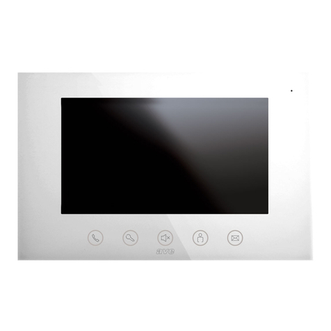
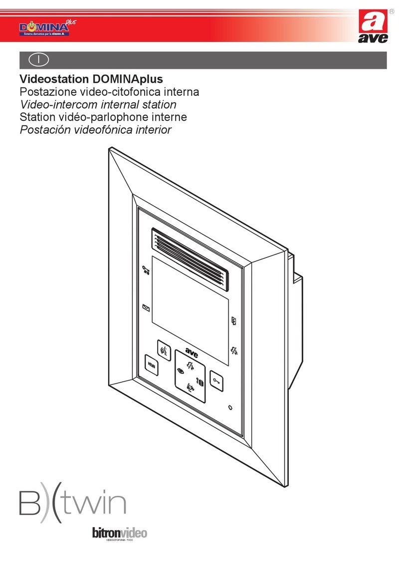
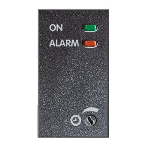
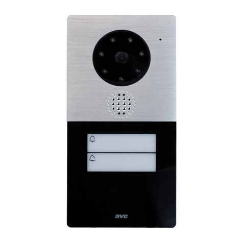
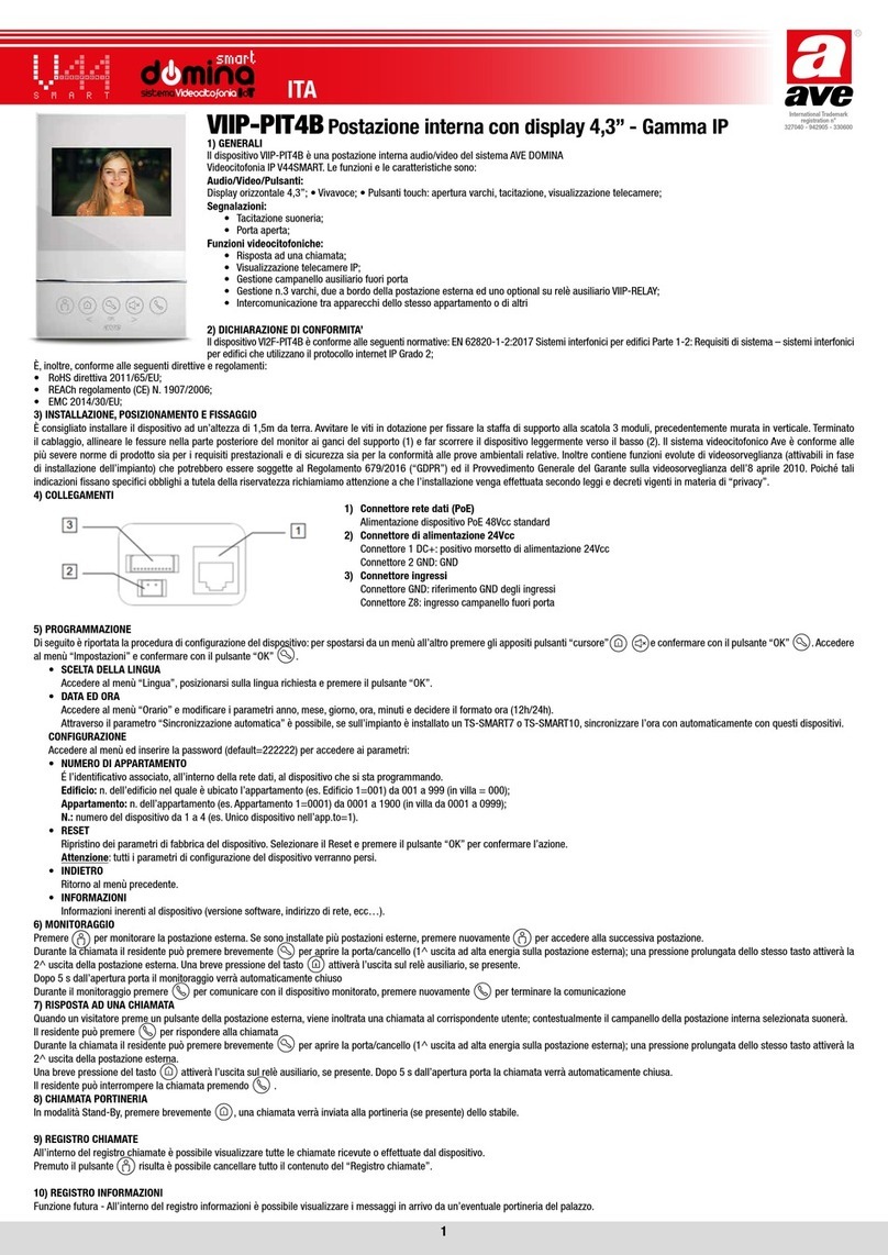
AVE DOMINA VI2F-PIT4B User manual

ITA
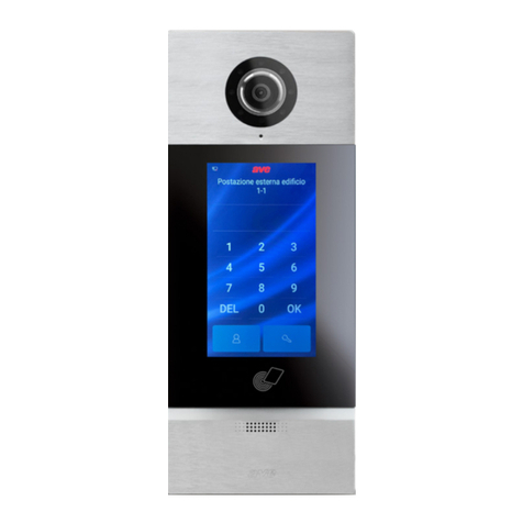
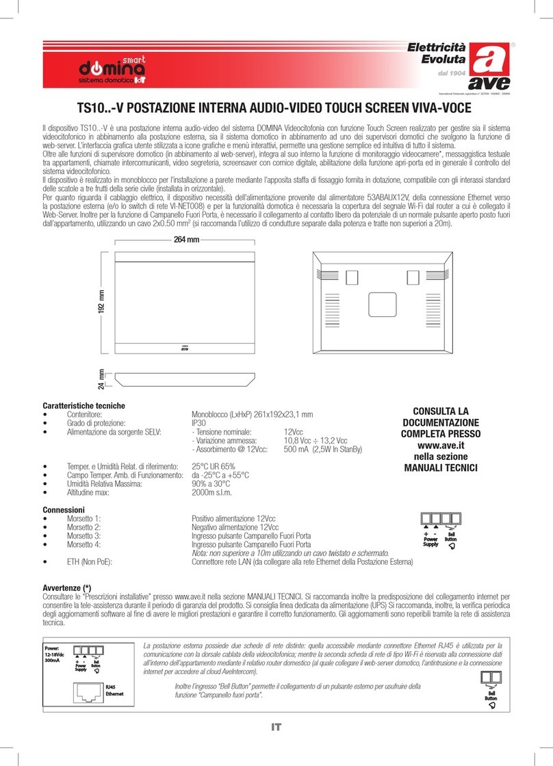
VI2F-PIT4B POSTAZIONE INTERNA CON DISPLAY 4,3” - GAMMA 2 FILI
1) GENERALI
Il dispositivo VI2F-PIT4B è una postazione interna audio/video del sistema AVE DOMINA Videocitofonia a 2 fili V44EASY. Le funzioni e le caratteristiche sono:
Audio/Video/Pulsanti:
• Display orizzontale 4,3”; • Vivavoce; • Pulsanti touch: apertura varchi, tacitazione, visualizzazione telecamere;
Segnalazioni:
• Tacitazione suoneria attiva; • Porta aperta;
Funzioni videocitofoniche:
• Risposta ad una chiamata; • Visualizzazione telecamere analogiche mediante apposita interfaccia VI2F-CAM; • Gestione campanello ausiliario fuori porta • Gestione
n.3 varchi, due a bordo della postazione esterna ed uno optional su relè ausiliario VI2F-RELAY; • Intercomunicazione tra apparecchi dello stesso appartamento o di altri
2) DICHIARAZIONE DI CONFORMITÀ’
Il dispositivo VI2F-PIT4B è conforme alle seguenti normative:
• EN 62820-1-1:2016 Sistemi interfonici per edifici Parte 1-1: Requisiti di sistema – Generale. Grado 2;
È, inoltre, conforme alle seguenti direttive e regolamenti:
• RoHS direttiva 2011/65/EU;
• REACh regolamento (CE) N. 1907/2006;
• EMC 2014/30/EU
3) INSTALLAZIONE, POSIZIONAMENTO E FISSAGGIO
È consigliato installare il dispositivo ad un’altezza di 1,5m da terra. Avvitare le viti in dotazione per fissare la staffa di supporto alla scatola 3 moduli, precedentemente murata in verticale. Terminato
il cablaggio, allineare le fessure nella parte posteriore del monitor ai ganci del supporto (1) e far scorrere il dispositivo leggermente verso il basso (2). Il sistema videocitofonico Ave è conforme alle
più severe norme di prodotto sia per i requisiti prestazionali e sicurezza sia per la conformità alle prove ambientali relative. Inoltre contiene funzioni evolute di videosorveglianza (attivabili in fase
di installazione dell’impianto) che potrebbero essere soggette al Regolamento 679/2016 (“GDPR”) ed il Provvedimento Generale del Garante sulla videosorveglianza dell’8 aprile 2010. Poiché tali
indicazioni fissano specifici obblighi a tutela della riservatezza richiamiamo attenzione a che l’installazione venga effettuata secondo leggi e decreti vigenti in materia di “privacy”.
4) COLLEGAMENTI
Di seguito è riportato il significato dei morsetti di collegamento e dei dip-switch posti nel retro del dispositivo (vedi Fig. 3):
BUS 2 fili Dip-switch 2 poli Ingresso pulsante campanello fuoriporta
Connettore maschio estraibile a 2 poli
polarizzato
• Morsetto 1: BUS A
• Morsetto 2: BUS B
• SW1-1 Impostazione Master/Slave dispositivo: spostare su (M) per assegnare il ruolo
di Master, su S per quello di Slave
• SW1-2 Adattamento di impedenza: spostare su ON (RC)quando la postazione è
l’ultima di una serie. Diversamente lasciare su OFF. Deve essere spostato su ON
anche se la stazione è collegata al distributore interno VI2F-PIDIST.
Connettore maschio polarizzato 2 poli (completo di cavetto
da 10 cm fornito a corredo)
• Terminale 1: GND
• Terminale 2: ingresso campanello
Nota: utilizzare pulsante normalmente aperto con libero da
potenziale.
5) INDIRIZZAMENTO
Entro 60 s dal power-on premere per 3 s il pulsante ; dopo un lungo “Beep” verrà aperta l’interfaccia di impostazione indirizzo
1. Impostazione indirizzo: premere brevemente (SU), l’indirizzo visualizzato sarà incrementato di 1. Premendolo a lungo l’indirizzo
verrà incrementato rapidamente (da 001 a 200). Premere (GIÙ) per diminuirlo nello stesso modo.
2. Salvataggio indirizzo: premere brevemente (OK), l’attuale numero di indirizzo verrà assegnato e salvato e il dispositivo entrerà in
Stand-By. Premere brevemente per uscire senza salvare il numero di indirizzo visualizzato.
6) SIGNIFICATO PULSANTI
Interfaccia di impostazione indirizzo
ADDRESS : 001
DOWN OK UP BACK
MICROFONO
DISPLAY
ALTOPARLANTE
LED
Verde ON:
Dispositivo alimentato
Verde lampeggiante:
Chiamata in corso
Rosso ON:
Tacitazione attiva
Lampeggio rosso/verde:
Porta aperta (vedi par. 6)
7” RAL 7023
4,3” RAL 7023
7” RAL 7023
4,3” RAL 7023
7” RAL 7023
4,3” RAL 7023
7” RAL 7023
4,3” RAL 7023
7” RAL 7023
4,3” RAL 7023
MONITOR:
apre il collegamento audio-video
con la postazione esterna #1;
premendo nuovamente il pulsante
vengono visualizzate le altre
postazioni esterne o eventuali
telecamere.
CHIAMATA PORTINERIA (se presente) /
SCORRIM. SINISTRA:
una postazione interna diviene
portineria quando gli è assegnato
l’indirizzo 200. A chiamata attiva, la
pressione del pulsante consente lo
sblocco del relè ausiliario (optional).
SERRATURA / OK:
nessuna funzione in Stand-by.
Apertura varchi della postazione
visualizzata in funzionamento.
Pressione breve: apertura varco #1
Pressione > 3 s: apertura varco #2
TACITAZIONE/ SCORRIM. DESTRA:
una breve pressione attiva/disattiva la tacitazione
della suoneria di chiamata (il LED diventerà rosso
quando la tacitazione è attiva). Una pressione
prolungata propagherà ad eventuali altre stazioni
slave dello stesso appartamento l’attivazione/
disattivazione della tacitazione.
CHIAMATA:
premere per accedere
all’interfaccia di
comunicazione e per
rispondere ad una chiamata
in arrivo.

7) ALLARME PORTA APERTA
Quando l’ingresso d’allarme “GS” presente sulla postazione esterna è sbilanciato da più di 2 minuti, il dispositivo emette una segnalazione ottica (il led lampeggia alternativamente di colore rosso
e verde) per segnalare che la porta è stata dimenticata aperta.
Nota: la segnalazione di porta aperta è inviata a tutte le postazioni interne dell’impianto; per bloccare la segnalazione è necessario provvedere alla chiusura della porta ad essa associata.
8) RISPOSTA AD UNA CHIAMATA
1. Quando un visitatore preme un pulsante della postazione esterna, viene inoltrata una chiamata a quell’Utente.
Contestualmente il campanello della postazione interna selezionata suonerà.
2. Il residente può premere per rispondere alla chiamata
3. Durante la chiamata il residente può premere brevemente per aprire la porta/cancello (1^ uscita ad alta energia sulla
postazione esterna); una pressione prolungata dello stesso tasto attiverà la 2^ uscita della postazione esterna.
Una breve pressione del tasto attiverà l’uscita sul relè ausiliario, se presente.
Dopo 5 s dall’apertura porta la chiamata verrà automaticamente chiusa.
4. Premendo è possibile spostare la visualizzazione su una video-camera di estensione, se presente.
5. Il residente può interrompere la chiamata premendo .
9) CHIAMATA PORTINERIA
Quando la postazione interna è in Stand-By il residente può chiamare la portineria se presente premendo
Nota: alla postazione interna “portineria” deve essere assegnato l’indirizzo 200.
10) MONITORAGGIO
1. Premere per monitorare la postazione esterna. Se sono installate più postazioni esterne, premere nuovamente per
accedere alla successiva postazione.
2. Durante la chiamata il residente può premere brevemente per aprire la porta/cancello (1^ uscita ad alta energia
sulla postazione esterna); una pressione prolungata dello stesso tasto attiverà la 2^ uscita della postazione esterna.
Una breve pressione del tasto attiverà l’uscita sul relè ausiliario, se presente.
Dopo 5 s dall’apertura porta il monitoraggio verrà automaticamente chiuso
3. Durante il monitoraggio premere per comunicare con il dispositivo monitorato, premere nuovamente per terminare
la comunicazione.
11) CHIAMATA INTERCOMUNICANTE
In modalità Stand-By, premere brevemente per accedere alla chiamata intercomunicante:
1. Premere il pulsante (SU) per incrementare o (GIÙ) per diminuire il numero dell’indirizzo del posto interno che si vuol
chiamare. Una pressione prolungata dello stesso pulsante incrementa/diminuisce velocemente il numero (min 001 max 200).
2. Premere, quindi, il pulsante (OK) per avviare la chiamata. Il dispositivo attiverà un tono di feedback per segnalarne lo stato
di chiamata in corso.
3. Premere brevemente per chiudere la pagina
12) IMPOSTAZIONI VIDEO
Quando il dispositivo è nello stato di suoneria attiva / Monitoraggio / Chiamata in corso, premere a lungo per accedere al
menù di impostazione del video.
1. Premere (GIÙ) o (SU) per scegliere su quale parametro si vuole agire: LUMINOSITÀ, CONTRASTO o COLORE
2. Dopo aver scelto il parametro da impostare premere (OK). La barra del cursore cambierà il proprio colore da giallo a verde
3. Premere (GIÙ) e (SU) per diminuire o aumentare il valore dello specifico parametro (LUMINOSITÀ, CONTRASTO,
COLORE) in un campo da 1 a 10. Per salvare il valore premere (OK); il prossimo parametro verrà proposto automaticamente.
4. Premere per uscire dal menù. Il dispositivo uscirà dal menù anche se non ci sono operazioni entro 5 s.
13) CARATTERISTICHE TECNICHE
Tensione di lavoro 30VDC Temperatura di funzionamento Da -10°C a +55°C
Tensione massima di lavoro 32VDC Altitudine max. 2000 m s.l.m.
Assorbimento in esercizio 170 mA max @ 30 VDC N. max di dispositivi installabili 4
Assorbimento in stand-by 7 mA max @ 30 VDC Montaggio Su scatole da incasso installate
verticalmente, con il supporto in dotazione
Dimensioni (L x H x P) 120 x 180 x 19,5 mm
Dimensioni LCD 4,3 pollici Grado di protezione IP20 (IP40 quando installato)
Risoluzione 480 x 272 pixel Classe ambientale secondo EN 62820-1-1 CLASSE III
PER SCARICARE IL MANUALE COMPLETO DEL SISTEMA 2 FILI SCANSIONA IL CODICE QR RIPORTATO NELLA PAGINA DEI DISEGNI
Interfaccia di chiamata
Interfaccia di chiamata portiere
INDOOR : 200
Chiamata Intercomunicante
INDOOR : 001
DOWN OK UP BACK
Interfaccia di impostazione LUMINOSITA’ video
DOWN OK UP BACK
BRIGHTNESS
BRIGHTNESS
5/10
5/10

ENG
VI2F-PIT4B INDOOR STATION WITH 4.3” DISPLAY - 2-WIRE RANGE
1) OVERVIEW
The VI2F-PIT4B is an indoor audio/video station of the AVE DOMINA system 2-wire video-intercom system V44EASY. The functions and characteristics are as follows:
Audio/Video/Buttons:
• 4.3” horizontal display; • Hands-free; • Touch buttons: gate opening, silencing, camera display;
Warnings:
• Active ringtone silencing; • Door open;
Video intercom functions:
• Answering a call; • Display of analogue cameras through a special VI2F-CAM interface; • Management of auxiliary outside door bell • Management of 3 gates, two on board the outdoor station and
one optional on auxiliary relay VI2F-RELAY; • Intercommunication between appliances of the same apartment or of other apartments
2) DECLARATION OF CONFORMITY
The VI2F-PIT4B device complies with the following standards:
• EN 62820-1-1:2016 Building intercom systems Part 1-1: System Requirements – General. Grade 2;
It also complies with the following directives and regulations:
• RoHS Directive 2011/65/EU;
• REACh Regulation (EC) No. 1907/2006;
• EMC 2014/30/EU
3) INSTALLATION, POSITIONING AND FIXING
The device should be installed at a height of 1.5m from the ground. Screw the screws supplied to secure the support bracket to the 3-module box, previously fixed to the wall in a vertical position.
Once wiring operations have been completed, align the slots in the back of the monitor with the bracket hooks (1) and slide the device slightly downwards (2). The AVE video-intercom system complies
with the strictest product standards both as regards performance and safety requirements and compliance with the relevant environmental tests. It also contains advanced video surveillance functions
(which can be activated during installation of the system) that may be subject to Regulation 679/2016 (“GDPR”) and the General Provision of the Video surveillance authority of 8 April 2010. Since these
indications establish specific obligations for the protection of privacy, we draw attention to the fact that the installation is carried out according to the current laws and legislative decrees on “privacy”.
4) CONNECTIONS
The meaning of the connection terminals and dip-switches located on the rear of the device is illustrated here below (see Fig. 3):
2-Wire BUS 2-pole dip-switch Input for the outside door bell button
Polarized 2-pole removable male
connector
• Terminal 1: BUS A
• Terminal 2: BUS B
• SW1-1 Device Master/Slave Setting: Move to (M) or to (S) to assign the Master or
Slave role, respectively
• SW1-2 Impedance matching: turn to ON (RC) when the station is the last in a series.
Otherwise, leave to OFF. It must be set to ON even if the station is connected to the
VI2F-PIDIST indoor distributor.
2-pole polarized male connector (complete with 10 cm
cable)
• Terminal 1: GND
• Terminal 2: door bell input
Note: use a potential-free normally open button
5) ADDRESSING
Within 60 s from power-on, press the button for 3 s; after a long “Beep” the interface for setting address
1. Address setting: press briefly (UP), the displayed address will be incremented by 1. Press and hold the address to
increase it quickly (from 001 to 200). Press (DOWN) to decrease it in the same way.
2. Saving the address: press briefly (OK); the current address number will be assigned and saved and the device will enter
the stand-by mode. Press briefly to exit without saving the displayed address number.
6) MEANING OF BUTTONS
Address setting interface
ADDRESS : 001
DOWN OK UP BACK
MICROPHONE
DISPLAY
LOUDSPEAKER
LED
Green ON:
Device powered
Flashing green:
Call in progress
Red ON:
Silencing active
Flashing red/green:
Door open (see par. 6)
7” RAL 7023
4,3” RAL 7023
7” RAL 7023
4,3” RAL 7023
7” RAL 7023
4,3” RAL 7023
7” RAL 7023
4,3” RAL 7023
7” RAL 7023
4,3” RAL 7023
MONITOR:
opens the audio-video connection
with outdoor station #1; press the
button again to display the other
outdoor stations or any cameras.
CONCIERGE CALL (if any) / LEFT
SCROLL:
an indoor station becomes a
concierge when it is assigned the
address 200. When the call is
active, press the button to unlock the
auxiliary relay (optional).
LOCK / OK:
no function in Stand-by. Opening
the gates of the currently
operating displayed station.
Short press: opening gate #1
Press > 3 s: opening gate #2
SILENCING / RIGHT SCROLL:
press briefly to activate/deactivate the ringtone
silencing (the LED will turn red when the
ringtone is active). Press and hold to propagate
the activation/deactivation of the silencing to any
other slave stations in the same apartment.
CALL:
press to access the
communication interface
and to answer an incoming
call.

7) DOOR OPEN ALARM
When the “GS” alarm input on the outdoor station has been unbalanced for more than 2 minutes, the device emits an optical signal
(the red and green led flashes alternately) to warn that the door has been left open.
Note: the open door signal is sent to all the indoor stations of the system; to stop the signal, close the door associated with it.
8) ANSWERING A CALL
1. When a visitor presses a button on the outdoor station, a call is forwarded to that User.
At the same time, the doorbell of the selected indoor station will ring.
2. The resident can press to answer the call
3. During the call, the resident can press briefly to open the door/gate (1st high energy output on the
outdoor station); press and hold the same key to activate the 2nd output of the outdoor station.
Press briefly the key to activate the output on the auxiliary relay, if present.
The call will be automatically closed 5 seconds after the door has been opened.
4. Press to switch the view to an extension video camera, if present.
5. The resident may stop the call by pressing .
9) CALLING THE CONCIERGE
When the indoor station is in Stand-By mode, the resident can call the concierge, if present, by pressing
Note: the address 200 must be assigned to the “concierge” indoor station.
10) MONITORING
1. Press to monitor the outdoor station. If multiple outdoor stations have been installed, press again to
access the next station.
2. During the call, the resident can press briefly to open the door/gate (1st high energy output on the
outdoor station); press and hold the same key to activate the 2nd output of the outdoor station.
Press briefly the key to activate the output on the auxiliary relay, if present.
Monitoring will be automatically closed 5 seconds after the door has been opened.
3. During monitoring press to communicate with the monitored device; press again to end
the communication.
11) INTERCOMMUNICATING CALL
In Stand-By mode, briefly press to access the intercommunicating call:
1. Press the (UP) button to increase or (DOWN) to decrease the number of the address of the indoor station to be
called. Press and hold the same button to quickly increase/decrease the number (min. 001 max. 200).
2. Then press the (OK) button to start the call. The device will activate a feedback tone to signal the
call-in-progress status.
3. Press briefly to close the page
12) VIDEO SETTINGS
When the device is in the active ringtone / Monitoring / Call-in-progress condition, press and hold to access the
video settings menu.
1. Press (DOWN) or (UP) to select the parameter to be edited: BRIGHTNESS, CONTRAST or COLOUR
2. After choosing the parameter to be set, press (OK). The cursor bar will switch from yellow to green
3. Press (DOWN) and (UP) to decrease or increase the value of the specific parameter (BRIGHTNESS, CONTRAST,
COLOUR) within a 1 to 10 range. To save the value, press (OK); the next parameter will be displayed automatically.
4. Press to exit the menu. The device will exit the menu also if no operation is performed within 5 s.
13) TECHNICAL CHARACTERISTICS
Operating voltage 30VDC Operating temperature From -10 °C to +55 °C
Maximum operating voltage 32VDC Maximum altitude 2000 m a.s.l.
Absorption during operation 170 mA max @ 30 VDC Maximum number of devices that can be installed 4
Absorption during stand-by 7 mA max @ 30 VDC Installation On vertically installed flush-mounted boxes,
using the support provided
Dimensions (L x H x D) 120 x 180 x 19.5 mm
LCD size 4.3 inches Protection rating IP20 (IP40 when installed)
Resolution 480 x 272 pixels Environmental class as per EN 62820-1-1 CLASS III
TO DOWNLOAD THE COMPLETE MANUAL OF THE 2-WIRE SYSTEM, SCAN THE QR CODE SHOWN ON THE DRAWINGS PAGE
Call interface
Concierge call interface
INDOOR: 200
Intercommunicating Call
INDOOR: 001
DOWN OK UP BACK
Video BRIGHTNESS setting interface
DOWN OK UP BACK
BRIGHTNESS
BRIGHTNESS
5/10
5/10

FRA
VI2F-PIT4B POSTE INTERNE AVEC AFFICHAGE 4,3” - GAMME 2 FILS
1) GÉNÉRALITÉS
Le dispositif VI2F-PIT4B est un poste interne audio/vidéo du système AVE DOMINA Visiophone à 2 fils V44EASY. Les fonctions et les caractéristiques sont les suivantes:
Audio/Vidéo/Boutons:
Affichage horizontal 4,3”; • Haut-parleur; • Boutons tactiles: ouvertures entrées, silencieux, visualisation caméras;
Signalisations:
• Silencieux sonnerie actif; • Porte ouverte;
Fonctions visiophone:
• Réponse à un appel; • Visualisation caméras analogiques par l’interface prévue à cet effet VI2F-CAM; • Gestion sonnette auxiliaire derrière la porte • Gestion 3 entrées, deux à bord de la platine de
rue et une en option sur le relais auxiliaire VI2F-RELAY; • Intercommunication entre appareils du même appartement ou d’autres
2) DÉCLARATION DE CONFORMITÉ
Le dispositif VI2F-PIT4B est conforme à la norme ci-dessous:
• EN 62820-1-1:2016 Systèmes d’interphone de bâtiment - Partie 1-1: Exigences du système - Généralités. Degré 2;
Il est également conforme aux directives et règlements ci-dessous:
• Directive RoHS 2011/65/UE;
• Règlement REACh (CE) N. 1907/2006;
• CEM 2014/30/UE
3) INSTALLATION, PLACEMENT ET FIXATION
Il est recommandé d’installer le dispositif à une hauteur de 1,5m du sol. Visser les vis fournies pour fixer le support au boîtier 3 modules, précédemment encastré verticalement. Terminer le câblage,
aligner les fentes à l’arrière du moniteur aux crochets du support (1) et faire coulisser légèrement le dispositif vers le bas(2). Le système de visiophone Ave est conforme aux normes les plus sévères
de produit, en ce qui concerne tant les exigences de prestations et de sécurité que la conformité aux tests environnementaux relatifs. Il comprend en outre des fonctions évoluées de vidéosurveillance
(à activer en phase d’installation du système) pouvant être soumises au Règlement 679/2016 («RGPD») et aux Dispositions générales du Garant sur la vidéosurveillance du 8 avril 2010. Ces
indications fixant des obligations précises de protection de la confidentialité, nous attirons l’attention sur le fait que l’installation est réalisée conformément aux lois et décrets en vigueur en matière
de «confidentialité».
4) BRANCHEMENTS
Ci-dessous, la signification des bornes de branchement et des interrupteurs DIP situés à l’arrière du dispositif (voir Fig. 3):
BUS 2 fils Interrupteur DIP 2 pôles Entrée bouton sonnette derrière la porte
Connecteur mâle amovible à 2 pôles
polarisé
• Borne 1: BUS A
• Borne 2: BUS B
• SW1-1 Configuration Maître/Esclave dispositif: déplacer sur (M) pour attribuer le
rôle de Maître, sur S pour celui d’Esclave
• SW1-2 Adaptation d’impédance: déplacer sur ON (RC) lorsque le poste est
le dernier d’une série. Sinon, laisser sur OFF. Il doit être déplacé sur ON
même si la station est reliée au distributeur interne VI2F-PIDIST.
Connecteur mâle polarisé 2 pôles (avec câble de 10cm
fourni)
• Terminal 1: GND
• Terminal 2: entrée sonnette
Remarque: utiliser un bouton normalement ouvert libre de
potentiel.
5) ADRESSAGE
Dans les 60s suivant l’allumage, appuyer pendant 3s sur le bouton ; après un «Bip» prolongé, l’interface de configuration d’adresse
s’ouvrira
1. Configuration d’adresse: appuyer brièvement sur (HAUT), l’adresse visualisée sera augmentée de 1. Si l’on appuie longtemps,
l’adresse augmentera rapidement (de 001 à 200). Appuyer sur (BAS) pour diminuer de la même façon.
2. Enregistrement adresse: appuyer brièvement sur (OK), le numéro d’adresse actuelle sera attribué et sauvegardé et le dispositif
entrera en Veille. Appuyer brièvement sur pour sortir sans enregistrer le numéro d’adresse visualisé.
6) SIGNIFICATION BOUTONS
Interface de configuration d’adresse
ADDRESS: 001
DOWN OK UP BACK
MICRO
AFFICHAGE
HAUT-PARLEUR
LED
Vert ON:
Dispositif alimenté
Vert clignotant:
Appel en cours
Rouge ON:
Silencieux activé
Clignotement rouge/vert:
Porte ouverte (voir par. 6)
7” RAL 7023
4,3” RAL 7023
7” RAL 7023
4,3” RAL 7023
7” RAL 7023
4,3” RAL 7023
7” RAL 7023
4,3” RAL 7023
7” RAL 7023
4,3” RAL 7023
MONITEUR:
ouvre la connexion audio-vidéo
avec la platine de rue #1; en
appuyant à nouveau sur le
bouton, les autres platines de rue
ou d’éventuelles caméras sont
visualisées.
APPEL CONCIERGERIE (le cas
échéant)/DÉFILEMENT À GAUCHE:
un poste interne devient conciergerie
lorsque l’adresse 200 lui est attribuée.
Lors d’un appel actif, la pression sur
le bouton permet le déverrouillage du
relais auxiliaire (en option).
SERRURE/OK:
aucune fonction en Veille. Ouverture
entrée du poste visualisée en
fonctionnement.
Pression brève:
ouverture entrée #1
Pression > 3s: ouverture
entrée #2
SILENCIEUX/DÉFILEMENT À DROITE:
une brève pression active/désactive le silencieux
de la sonnerie d’appel (la LED devient rouge
lorsque le silencieux est actif). Une pression
prolongée propage à d’éventuelles autres
stations esclaves du même appartement
l’activation/désactivation du silencieux.
APPEL:
appuyer pour accéder
à l’interface de
communication et pour
répondre à un appel entrant.

7) ALARME PORTE OUVERTE
Lorsque l’entrée d’alarme «GS» présente sur la platine de rue est déséquilibrée depuis plus de 2 minutes, le dispositif émet un
signal optique (la LED clignote en alternance rouge et vert) pour signaler que la porte a été laissée ouverte.
Remarque: le signal de porte ouverte est envoyé à tous les postes internes du système; pour bloquer le signal, il est nécessaire de
fermer la porte associée à ce dernier.
8) RÉPONSE À UN APPEL
1. Lorsqu’un visiteur appuie sur un bouton de la platine de rue, un appel est transmis à l’Utilisateur correspondant.
Au même moment, la sonnette du poste interne sélectionné sonne.
2. Le résident peut appuyer sur pour répondre à l’appel
3. Durant l’appel, le résident peut appuyer brièvement sur pour ouvrir la porte/le portail (1ère sortie à haute énergie sur la
platine de rue); une pression prolongée sur la même touche active la 2esortie de la platine de rue.
Une pression brève sur la touche active la sortie sur le relais auxiliaire, le cas échéant.
5s après l’ouverture de la porte, l’appel est automatiquement fermé.
4. En appuyant sur , il est possible de déplacer la visualisation sur une caméra d’extension, le cas échéant.
5. Le résident peut interrompre l’appel en appuyant sur .
9) APPEL CONCIERGERIE
Lorsque le poste interne est en veille, le résident peut appeler la conciergerie, le cas échéant, en appuyant sur
Remarque: l’adresse 200 doit être attribuée au poste interne «conciergerie».
10) SURVEILLANCE
1. Appuyer sur pour surveiller la platine de rue. Si plusieurs platines de rue sont installées, appuyer à nouveau sur pour
accéder à la platine suivante.
2. Durant l’appel, le résident peut appuyer brièvement sur pour ouvrir la porte/le portail (1ère sortie à haute énergie
sur la platine de rue); une pression prolongée sur la même touche active la 2esortie de la platine de rue.
Une pression brève sur la touche active la sortie sur le relais auxiliaire, le cas échéant.
5s après l’ouverture de la porte, la surveillance est automatiquement fermée
3. Durant la surveillance, appuyer sur pour communiquer avec le dispositif surveillé, appuyer à nouveau sur pour
terminer la communication.
11) APPEL D’INTERCOMMUNICATION
En mode Veille, appuyer brièvement sur pour accéder à l’appel d’intercommunication:
1. Appuyer sur le bouton (HAUT) pour augmenter ou sur (BAS) pour diminuer le numéro de l’adresse du poste interne que
l’on souhaite appeler. Une pression prolongée sur le même bouton augmente/diminue rapidement le numéro (min 001 max 200).
2. Appuyer ensuite sur le bouton (OK) pour démarrer l’appel. Le dispositif active un son de feedback pour en signaler l’état
d’appel en cours.
3. Appuyer brièvement sur pour fermer la page
12) PARAMÈTRES VIDÉO
Lorsque le dispositif est en état de Sonnerie active/Surveillance/Appel en cours, appuyer longuement sur pour accéder au
menu de configuration de la vidéo.
1. Appuyer sur (BAS) ou (HAUT) pour choisir le paramètre sur lequel on veut agir: LUMINOSITÉ, CONTRASTE OU COULEUR
2. Après avoir choisi le paramètre à configurer, appuyer sur (OK). La barre du curseur change de couleur, de jaune à vert
3. Appuyer sur (BAS) et (HAUT) pour diminuer ou augmenter la valeur du paramètre spécifique (LUMINOSITÉ, CONTRASTE,
COULEUR) dans un champ de 1 à 10. Pour enregistrer la valeur, appuyer sur (OK); le prochain paramètre est proposé
automatiquement.
4. Appuyer sur pour quitter le menu. Le dispositif quitte également le menu si aucune opération n’est effectuée dans les 5s.
13) CARACTÉRISTIQUES TECHNIQUES
Tension de travail 30VCC Température de fonctionnement De -10°C à +55°C
Tension maximale de travail 32VCC Altitude max. 2000m au-dessus du niveau de la mer
Absorption de fonctionnement 170mA max @ 30VCC Nombre max de dispositifs pouvant être installés 4
Absorption en veille 7mA max @ 30VCC Montage Sur des boîtiers d’encastrement installés
verticalement, avec le support fourni
Dimensions (L x h x P) 120 x 180 x 19,5mm
Dimensions LCD 4,3 pouces Degré de protection IP20 (IP40 à l’installation)
Résolution 480 x 272 pixel Classe environnementale selon EN 62820-1-1 CLASSE III
POUR TÉLÉCHARGER LE MANUEL COMPLET DU SYSTÈME 2 FILS, SCANNER LE CODE QR FIGURANT À LA PAGE DES ILLUSTRATIONS
Interface d’appel
Interface d’appel concierge
INDOOR: 200
Appel d’intercommunication
INDOOR: 001
DOWN OK UP BACK
Interface de configuration LUMINOSITÉ vidéo
DOWN OK UP BACK
BRIGHTNESS
BRIGHTNESS
5/10
5/10

ES
VI2F-PIT4B ESTACIÓN INTERIOR CON PANTALLA 4,3” - GAMA 2 HILOS
1) GENERALES
El dispositivo VI2F-PIT4B es una estación interior audio/vídeo del sistema AVE DOMINA Videoportero de 2 hilos V44EASY. Las funciones y las características son:
Audio/Vídeo/Botones:
• Pantalla horizontal 4,3”; • Manos libres; • Botones táctiles: apertura pasos, silenciamiento, visualización cámaras;
Señales:
• Silenciamiento timbre de llamada activa; • Puerta abierta;
Funciones del videoportero:
• Respuesta a una llamada • Visualización cámaras analógicas mediante interfaz correspondiente VI2F-CAM • Gestión timbre auxiliar fuera puerta • Gestión n.3 pasos, dos en la estación exterior y uno
opcional en relé auxiliar VI2F-RELAY • Intercomunicación entre equipos del mismo piso o de
2) DECLARACIÓN DE CONFORMIDAD
El dispositivo VI2F-PIT4B está conforme con las siguientes normativas:
• EN 62820-1-1:2016 Sistemas de intercomunicación de edificios Parte 1-1: Requisitos de sistema – General. Grado 2;
Está, también, conforme con las siguientes directivas y reglamentos:
• Directiva RoHS 2011/65/EU;
• Reglamento REACh (CE) N. 1907/2006;
• EMC 2014/30/EU
3) INSTALACIÓN, COLOCACIÓN Y FIJACIÓN
Se recomienda instalar el dispositivo a una altura de 1,5m del suelo. Apriete los tornillos en dotación para fijar el estribo de soporte a la caja 3 módulos, previamente tapiada en vertical. Una vez
completado el cableado, alinee las ranuras en la parte posterior del monitor con los ganchos del soporte (1) y deslice el dispositivo hacia abajo ligeramente (2). El videoportero Ave cumple las más
estrictas normas de producto tanto en lo que respecta a los requisitos de rendimiento y seguridad como en el cumplimiento de las pruebas ambientales pertinentes. Además, contiene funciones
avanzadas de videovigilancia (que pueden activarse durante la instalación del sistema) que podrían estar sujetas al Reglamento 2016/679 (“RGPD”) y a la Disposición General del Garante sobre
videovigilancia del 8 de abril de 2010. Dado que estas indicaciones establecen obligaciones específicas para proteger la confidencialidad, llamamos la atención a que la instalación se efectúe de
acuerdo con las leyes y decretos vigentes en materia de “privacidad”.
4) CONEXIONES
A continuación se señala el significado de los bornes de conexión y de los interruptores dip colocados en la parte trasera del dispositivo (vea Fig. 3):
BUS 2 hilos Interruptor dip 2 polos Entrada botón timbre fuera puerta
Conector macho extraíble de 2 polos
polarizado
• Borne 1: BUS A
• Borne 2: BUS B
• SW1-1 Configuración Maestro/Esclavo dispositivo: desplace a (M) para asignar el rol
de Maestro, a S para el de Esclavo
• SW1-2 Adaptación de impedancia: lleve a ON (RC) cuando la estación es
la última de una serie. De otro modo deje en OFF. Debe desplazarse a ON
incluso si la estación está conectada al distribuidor interno VI2F-PIDIST.
Conector macho polarizado 2 polos (dotado de cablecito de
10 cm suministrado)
• Terminal 1: GND
• Terminal 2: entrada timbre
Nota: utilice botón normalmente abierto libre de
potencial.
5) DIRECCIÓN
En 60 s desde el power-on presione por 3 s el botón ; después de un largo “Beep” se abrirá la interfaz de configuración dirección
1. Configuración dirección: presione por un tiempo breve (ARRIBA), la dirección visualizada se incrementará 1. Presionándolo por un
tiempo largo la dirección. Se incrementará rápidamente (de 001 a 200). Presione (ABAJO) para disminuirla del mismo modo.
2. Guardado dirección: presione por un tiempo corto (OK), el número actual de dirección se asignará y guardará y el dispositivo
entrará en Espera. Presione por un tiempo corto para salir sin guardar el número de dirección visualizado.
6) SIGNIFICADO BOTONES
Interfaz de configuración dirección
ADDRESS: 001
DOWN OK UP BACK
MICRÓFONO
PANTALLA
ALTAVOZ
LED
Verde ON:
Dispositivo alimentado
Verde intermitente:
Llamada en curso
Rojo ON:
Silenciamiento activo
Parpadeo rojo/verde:
Puerta abierta (vea párr. 6)
7” RAL 7023
4,3” RAL 7023
7” RAL 7023
4,3” RAL 7023
7” RAL 7023
4,3” RAL 7023
7” RAL 7023
4,3” RAL 7023
7” RAL 7023
4,3” RAL 7023
MONITOR:
abre la conexión audio-vídeo
con la estación exterior #1;
presionando nuevamente el botón
se visualizan las otras estaciones
exteriores o eventuales cámaras.
LLAMADA A PORTINERÍA (si está
presente) / DESLIZ. IZQUIERDA:
una estación interior se vuelve
portinería cuando se le ha asignado
la dirección 200. A llamada activa,
la presión del botón permite el
desbloqueo del relé auxiliar (opcional).
CERRADURA / OK:
ninguna función en Espera.
Apertura pasos de la estación
visualizada en funcionamiento.
Presión breve: apertura paso #1
Presión > 3 s: apertura paso #2
SILENCIAMIENTO/ DESLIZA. DERECHA:
una breve presión activa/desactiva el
silenciamiento del timbre de llamada (el LED
se volverá rojo cuando el silenciamiento está
activo). Una presión prolongada propagará
a otras eventuales estaciones esclavas del
mismo piso la activación/desactivación del
silenciamiento.
LLAMADA:
presione para acceder a la
interfaz de comunicación
y para responder a una
llamada entrante.

7) ALARMA PUERTA ABIERTA
Cuando la entrada de alarma “GS” presente en la estación exterior está desequilibrada durante más de 2 minutos, el dispositivo
emite una señal óptica (el led parpadea de modo alternativo en rojo y verde) para indicar que se ha olvidado cerrar la puerta.
Nota: la señal de puerta abierta se envía a todas las estaciones interiores del sistema; para bloquear la señal, es necesario cerrar la
puerta asociada.
8) RESPUESTA A UNA LLAMADA
1. Cuando un visitante presiona un botón de la estación exterior, se envía una llamada a ese usuario.
Contextualmente el timbre de la estación interior seleccionada sonará.
2. El residente puede presionar para responder la llamada
3. Durante la llamada el residente puede presionar por un corto tiempo para abrir la porta/cancela (1^ salida de alta energía
en la estación exterior); una presión prolongada de la misma tecla activará la 2^ salida de la estación exterior.
Una presión corta del botón activará la salida del relé auxiliar, si está presente.
Después de 5 s desde la apertura de la puerta, se cerrará automáticamente.
4. Presionando es posible mover la visualización a una vídeo-cámara de extensión, si está presente.
5. El residente puede interrumpir la llamada presionando .
9) LLAMADA PORTINERÍA
Cuando la estación interior está en espera el residente puede llamar a la portería, si la hay, presionando
Nota: a la estación interior “portería” debe asignársele la dirección 200.
10) MONITORIZACIÓN
1. Presione para monitorizar la estación exterior. Si están instaladas varias estaciones exteriores, presione nuevamente
para acceder a la estación sucesiva.
2. Durante la llamada el residente puede presionar por un corto tiempo para abrir la porta/cancela (1^ salida de alta energía
En la estación exterior); una presión prolongada de la misma tecla activará la 2^ salida de la estación exterior.
Una presión corta del botón activará la salida del relé auxiliar, si está presente.
Después de 5 segundos desde la apertura la monitorización se cerrará automáticamente
3. Durante la monitorización presione para comunicar con el dispositivo monitorizado, presione nuevamente para
terminar la comunicación.
11) LLAMADA COMUNICANTE
En modalidad Espera, presione por un corto tiempo para acceder a la llamada comunicante:
1. Presione el botón (ARRIBA) para aumentar o (ABAJO) para disminuir el número de la dirección del puesto interior al
que se desea llamar. Una presión prolongada del mismo botón aumenta/disminuye rápidamente el número (mín 001 máx 200).
2. Presione, luego, el botón (OK) para dar inicio a la llamada. El dispositivo activará un tono de feedback para señalar el
estado de llamada en curso.
3. Presione por un corto tiempo para cerrar la página
12) CONFIGURACIONES VÍDEO
Cuando el dispositivo se encuentra en el estado timbre de llamada activo / Monitorización / Llamada en curso, presione por largo
tiempo para acceder al menú de configuración del vídeo.
1. Presione (ABAJO) o (ARRIBA) para escoger en cuál parámetro se desea proceder: BRILLO, CONTRASTE o COLOR
2. Después de haber escogido el parámetro a configurar presione (OK). La barra del cursor cambará el propio color de
amarillo a verde
3. Presione (ABAJO) y (ARRIBA) para disminuir o aumentar el valor del parámetro específico (BRILLO, CONTRASTE,
COLOR) en un campo de 1 a 10. Para guardar el valor presione (OK); el próximo parámetro se propondrá automáticamente.
4. Presione para salir del menú. El dispositivo saldrá del menú incluso si no hay operaciones en 5 s.
13) CARACTERÍSTICAS TÉCNICAS
Tensión de trabajo 30VDC Temperatura de funcionamiento De -10°C a +55°C
Tensión máxima de trabajo 32VDC Altitud máx. 2000m s.n.m.
Absorción en ejercicio 170 mA máx @ 30 VDC N. máx de dispositivos instalables 4
Absorción en stand-by 7 mA máx @ 30 VDC Montaje En cajas a empotrar instaladas
verticalmente, con el soporte suministrado
Dimensiones (L x H x P) 120 x 180 x 19,5 mm
Dimensiones LCD 4,3 pulgadas Grado de protección IP20 (IP40 cuando instalado)
Resolución 480 x 272 pixeles Clase ambiental según EN 62820-1-1 CLASE III
PARA DESCARGAR EL MANUAL DOTADO DEL SISTEMA DE 2 HILOS ESCANEA EL CÓDIGO QR SEÑALADO EN LA PÁGINA DE LAS FIGURAS
Interfaz de llamada
Interfaz de llamada portero
INDOOR: 200
Llamada comunicante
INDOOR: 001
DOWN OK UP BACK
Interfaz de configuración BRILLO vídeo
DOWN OK UP BACK
BRIGHTNESS
BRIGHTNESS
5/10
5/10

DE
VI2F-PIT4B INNENSTATION MIT 4,3“-DISPLAY - 2-DRAHT
1) ALLGEMEINES
Beim Gerät VI2F-PIT4B handelt es sich um eine Audio-/Video-Innenstation des AVE DOMINA 2-Draht-Video-Türsprechsystems V44EASY. Die Funktionen und Merkmale im Überblick:
Audio/Video/Tasten:
• Horizontales 4,3“-Display; • Freisprecheinrichtung; • Touch-Tasten: Tor-Öffnung, Stummschaltung, Videokamera-Anzeige;
Signalisierungen:
• Stummschaltung Klingelton aktiv; • Tür offen;
Video-Türsprechanlagen-Funktionen:
• Beantworten eines Anrufs; • Anzeige von analogen Videokameras über eine spezielle VI2F-CAM-Schnittstelle; • Verwaltung der Zusatz-Türklingel; • Verwaltung von 3 Toren, zwei an der Außenstation
und ein optionales am Zusatzrelais VI2F-RELAY; • Kommunikation zwischen Geräten in derselben oder anderen Wohnungen
2) KONFORMITÄTSERKLÄRUNG
Das Gerät VI2F-PIT4B erfüllt die Anforderungen folgender Normen:
• EN 62820-1-1:2016 Gebäude-Sprechanlagen Teil 1-1: Generelle Systemanforderungen. Grad 2.
Es erfüllt außerdem die Anforderungen folgender Richtlinien und Verordnungen:
• RoHS-Richtlinie 2011/65/EU.
• REACH-Verordnung (EG) Nr. 1907/2006.
• EMV 2014/30/EU
3) INSTALLATION, POSITIONIERUNG UND BEFESTIGUNG
Es wird empfohlen, das Gerät in einer Höhe von 1,5 m über dem Boden zu installieren. Schrauben Sie die mitgelieferten Schrauben fest, um die Halterung auf dem zuvor vertikal eingemauerten
3-Modul-Gehäuse zu befestigen. Richten Sie nach der Verkabelung die Schlitze auf der Rückseite des Monitors an den Haken der Halterung aus (1) und schieben Sie das Gerät leicht nach unten (2).
Das Ave-Video-Türsprechsystem wird nach den strengsten Produktnormen für Leistungs- und Sicherheitsanforderungen sowie unter Einhaltung einschlägiger Umweltvorschriften hergestellt. Es verfügt
außerdem über erweiterte Videoüberwachungsfunktionen (die bei der Installation der Anlage aktiviert werden können), die der Verordnung (EU) 2016/679 („DSGVO“) und der allgemeinen Bestimmungen
des Garanten in Bezug auf die Videoüberwachung vom 8. April 2010 unterliegen können. Da diese Leitlinien besondere Verpflichtungen zum Schutz der Privatsphäre enthalten, möchten wir Sie darauf
aufmerksam machen, dass die Installation gemäß den geltenden Datenschutzverordnungen und -gesetzen erfolgen muss.
4) ANSCHLÜSSE
Die Bedeutung der Anschlussklemmen und Dip-Schalter auf der Rückseite des Geräts ist nachfolgend dargestellt (siehe Abb. 3):
Bus 2-Draht 2-poliger Dip-Schalter Eingang Türklingel-Taste
Anschluss männlich, abnehmbar,
2-polig, polarisiert
• Klemme 1: BUS A
• Klemme 2: BUS B
• SW1-1 Master/Slave-Geräteeinstellung: auf (M) stellen, um die Master-Rolle
zuzuweisen, auf S für Slave.
• SW1-2 Impedanzanpassung: auf ON (RC) stellen, wenn die Station die letzte einer
Serie ist. Andernfalls auf OFF lassen. Muss auf ON gestellt werden, auch wenn die
Station an den internen Verteiler VI2F-PIDIST angeschlossen ist.
Anschluss männlich, 2-polig, polarisiert (komplett mit
mitgeliefertem 10-cm-Kabel)
• Klemme 1: GND
• Klemme 2: Eingang Klingel
Hinweis: Verwenden Sie eine potentialfreie Arbeitskontakt-
Taste.
5) ADRESSIERUNG
Drücken Sie innerhalb von 60 Sekunden nach dem Einschalten die Taste für 3 Sekunden; nach einem langen Piepton wird die Adresseinstellungs-Schnittstelle geöffnet.
1. Adresseinstellung: Drücken Sie kurz (OBEN) und die angezeigte Adresse wird um 1 erhöht. Durch langes Drücken wird die Adresse
schnell erhöht (von 001 bis 200). Drücken Sie (UNTEN), um sie auf die gleiche Weise zu verringern.
2. Speichern der Adresse: Drücken Sie kurz (OK), die aktuelle Adressnummer wird zugewiesen und gespeichert und das Gerät geht
in den Standby-Modus. Drücken Sie kurz , um den Vorgang zu beenden, ohne die angezeigte Adressnummer zu speichern.
6) BEDEUTUNG DER TASTEN
MIKROFON
DISPLAY
LAUTSPRECHER
LED
Grün ON:
Gerät eingeschaltet
Grün blinkend:
Anruf im Gange
Rot ON:
Stummschaltung aktiv
Rot/Grün blinkend:
Tür offen (siehe Abschn. 6)
7” RAL 7023
4,3” RAL 7023
7” RAL 7023
4,3” RAL 7023
7” RAL 7023
4,3” RAL 7023
7” RAL 7023
4,3” RAL 7023
7” RAL 7023
4,3” RAL 7023
MONITOR:
stellt die Audio-Video-Verbindung
mit der Außenstation #1 her;
durch erneutes Drücken der
Taste werden die anderen
Außenstationen oder eventuelle
Videokameras angezeigt.
ANRUFEN DER PORTIERSTELLE (falls
vorhanden) / LINKS BLÄTTERN:
Eine Innenstation wird zur
Portierstelle, wenn sie die Adresse
200 erhält. Wenn der Anruf aktiv ist,
wird durch Drücken der Taste das
Zusatzrelais (optional) entriegelt.
SPERRE / OK:
keine Funktion im Standby.
Öffnung der Tore der im Betrieb
angezeigten Station.
Kurzes
Drücken: Öffnung Tor #1
Drücken > 3 s: Öffnung Tor #2
STUMMSCHALTUNG / RECHTS BLÄTTERN:
Ein kurzes Drücken aktiviert/deaktiviert die
Stummschaltung des Anrufklingeltons (die
LED leuchtet rot, wenn die Stummschaltung
aktiviert ist). Ein längeres Drücken überträgt die
Aktivierung/Deaktivierung der Stummschaltung
auf andere Slave-Stationen der gleichen
Wohnung.
ANRUF:
drücken, um auf die
Kommunikations-
Schnittstelle zuzugreifen
und einen eingehenden
Anruf entgegenzunehmen.
Adresseinstellungs-Schnittstelle
ADDRESS : 001
DOWN OK UP BACK

7) ALARM „TÜR OFFEN“
Wenn der Alarmeingang „GS“ an der Außenstation länger als 2 Minuten unsymmetrisch ist, gibt das Gerät ein optisches Signal ab (die LED blinkt abwechselnd rot und grün), um zu signalisieren,
dass die Tür offen gelassen wurde.
Hinweis: Die Signalisierung „Tür offen“ wird an alle Innenstationen der Anlage gesendet; um die Signalisierung zu stoppen, muss die entsprechende Tür geschlossen werden.
8) BEANTWORTEN EINES ANRUFS
1. Wenn ein Besucher eine Taste an der Außenstation drückt, wird der jeweilige Benutzer angerufen.
Gleichzeitig läutet die Klingel der gewählten Innenstation.
2. Der Bewohner kann drücken, um den Anruf entgegenzunehmen.
3. Während des Anrufs kann der Bewohner kurz drücken, um die Tür / das Tor zu öffnen (1. Ausgang mit hoher Energie an der
Außenstation); ein längeres Drücken derselben Taste aktiviert den 2. Ausgang der Außenstation.
Durch kurzes Drücken der Taste wird der Ausgang des Zusatzrelais, falls vorhanden, aktiviert.
5 Sekunden nach dem Öffnen der Tür wird der Anruf automatisch beendet.
4. Durch Drücken von können Sie die Anzeige auf eine Erweiterungs-Videokamera umschalten, falls vorhanden.
5. Der Bewohner kann den Anruf durch Drücken von unterbrechen.
9) ANRUFEN DER PORTIERSTELLE
Wenn sich die Innenstation im Standby-Modus befindet, kann der Bewohner die Portierstelle (falls vorhanden) anrufen,
indem er drückt.
Hinweis: Der Innenstation „Portierstelle“ muss die Adresse 200 zugewiesen werden.
10) ÜBERWACHUNG
1. Drücken Sie , um die Außenstation zu überwachen. Wenn mehrere Außenstationen installiert sind, drücken Sie
erneut , um zur nächsten Station zu gelangen.
2. Während des Anrufs kann der Bewohner kurz drücken, um die Tür / das Tor zu öffnen (1. Ausgang mit hoher Energie
an der Außenstation); ein längeres Drücken derselben Taste aktiviert den 2. Ausgang der Außenstation.
Durch kurzes Drücken der Taste wird der Ausgang des Zusatzrelais, falls vorhanden, aktiviert.
5 Sekunden nach dem Öffnen der Tür wird die Überwachung automatisch beendet.
3. Drücken Sie während der Überwachung , um mit dem überwachten Gerät zu kommunizieren, drücken Sie erneut ,
um die Kommunikation zu beenden.
11) INTERKOMMUNIKATIVER ANRUF
Drücken Sie im Standby-Modus kurz auf , um zum interkommunikativen Anruf zu gelangen:
1. Drücken Sie die Taste (OBEN), um die Nummer der Innenstation, die Sie anrufen möchten, zu erhöhen oder die Taste
(UNTEN), um sie zu verringern. Ein langes Drücken derselben Taste erhöht/verringert die Nummer schnell (min. 001 max. 200).
2. Drücken Sie dann die Taste (OK), um den Anruf zu starten. Das Gerät gibt einen Feedback-Ton aus, um zu signalisieren,
dass ein Anruf im Gange ist.
3. Drücken Sie kurz , um die Seite zu schließen.
12) VIDEO-EINSTELLUNGEN
Wenn sich das Gerät im Status „Klingelton aktiv“ / „Überwachung“ / „Anruf im Gange“ befindet, drücken Sie lange auf , um das
Menü „Video-Einstellungen“ aufzurufen.
1. Drücken Sie (UNTEN) oder (OBEN), um den Parameter auszuwählen, den Sie einstellen möchten: HELLIGKEIT,
KONTRAST oder FARBE
2. Nachdem Sie den einzustellenden Parameter ausgewählt haben, drücken Sie (OK). Die Farbe des Schiebereglers ändert
sich von gelb auf grün.
3. Drücken Sie (UNTEN) und (OBEN), um den Wert des jeweiligen Parameters (HELLIGKEIT, KONTRAST,
FARBE) in einem Bereich von 1 bis 10 zu erhöhen oder zu verringern. Um den Wert zu speichern, drücken Sie (OK); der
nächste Parameter wird automatisch vorgeschlagen.
4. Drücken Sie , um das Menü zu verlassen. Das Gerät verlässt das Menü auch dann, wenn innerhalb von 5 s keine Aktion
erfolgt.
13) TECHNISCHE MERKMALE
Betriebsspannung 30VDC Betriebstemperatur Von -10 °C bis +55 °C
Maximale Betriebsspannung 32VDC Max. Höhe 2000m s.l.m.
Betriebsstromaufnahme 170 mA max @ 30 VDC Max. Anzahl der installierbaren Geräte 4
Stromaufnahme im Standby-Betrieb 7 mA max @ 30 VDC Montage Auf vertikal installierten Unterputz-
Gehäusen mit der mitgelieferten Halterung
Abmessungen (B x H x T) 120 x 180 x 19,5 mm
LCD-Abmessungen 4,3 Zoll Schutzart IP20 (IP40 wenn installiert)
Auflösung 480 x 272 Pixel Umweltklasse nach EN 62820-1-1 KLASSE III
ZUM HERUNTERLADEN DES VOLLSTÄNDIGEN HANDBUCHS DES 2-DRAHT-SYSTEMS SCANNEN SIE DEN QR-CODE AUF DER ZEICHNUNGSSEITE
Anruf-Schnittstelle
Anruf-Schnittstelle Portierstelle
INDOOR : 200
Interkommunikativer Anruf
INDOOR : 001
DOWN OK UP BACK
Einstellungsschnittstelle Video-HELLIGKEIT
DOWN OK UP BACK
BRIGHTNESS
BRIGHTNESS
5/10
5/10

AR
- “4,3 VI2F-PIT4B
(1
V44EASY
AVE DOMINA / VI2F-PIT4B
//
, , •
• “4,3 •
•
•
3 •
• VI2F-CAM
• •
• VI2F-RELAY
(2
VI2F-PIT4B
2 –
1-1 -
EN 62820-1-12016 •
2011/65/EU •
1907/2006 (
) •
2014/30/EU
•
(3
3
15
Ave
(2) (1)
2016/679
(
)
2010 8 (« »)
«»
(4
(3 )
dip-
2
2 Dip-
2
A 1 •
B 2 •
S
(M) /
SW1-1 •
(RC) ON SW1-2 •
ON OFF
VI2F-PIDIST
10 ) 2
(
GND 1 •
2 •
(5
3 60
1 ()
1
() (200 001 )
()
2
(6
001
/
(6 )
7” RAL 7023
4,3” RAL 7023
7” RAL 7023
4,3” RAL 7023
7” RAL 7023
4,3” RAL 7023
7” RAL 7023
4,3” RAL 7023
7” RAL 7023
4,3” RAL 7023
-
1 #
/ ( )
200
()
/
#1
#2 3 <
/
/
)
(
/

INDOOR 200
INDOOR 001
5/10
5/10
(7
)
«GS»
(
(8
1
2
^1 ) /
3
^2
(
5
4
5
(9
200 «»
(10
1
^1 ) /
2
^2
(
5
3
(11
,
()
() 1
(200
001
) /
(OK) 2
3
(12
//
,
() () 1
(OK) 2
, ,) () () 3
(OK) 10 1
(
5
4
(13
30 °55+ °10-
32
2000
30 @
170
4
30 @
7
( × × ) 19,5 × 180 × 120
LCD 4,3 (
IP40) IP20
272 × 480EN 62820-1-1

150cm
1
3
SUPPORTO - SUPPORT
SUPPORT - SOPORTE
HALTERUNG -
2
SCATOLA MURATA
RECESSED BOX
BOÎTIER ENCASTRÉ
CAJA TAPIADA
EINGEMAUERTES GEHÄUSE
MURO - WALL - MUR
PARED - WAND -
ON
MRC
S NC
1
1
2
2
ON
1 2
3
MANUALE COMPLETO SISTEMA 2 FILI
COMPLETE MANUAL FOR 2-WIRE SYSTEM
MANUEL COMPLET SYSTÈME 2 FILS
MANUAL DOTADO DE SISTEMA DE 2 HILOS
VOLLSTÄNDIGES HANDBUCH
2-DRAHT-SYSTEM
VITI - SCREWS -
VIS - TORNILLOS -
SCHRAUBEN -


C0782 - 02 - 060722
www.ave.it
800 015 072
International Trademark
registration n°
327040 - 942905 - 330600
NOTES
Pour la durée et les conditions de garantie de chacun des produits, veuillez consulter le site www.ave.it et le catalogue commercial en vigueur. Les produits doivent commercialisés dans l’emballage d’origine.
Dans le cas contraire, le revendeur et/ou l’installateur sont obligés d’appliquer et de transmettre à l’utilisateur les instructions qui accompagnent le produit et/ou qui sont publiées sur www.ave.it et sur le
catalogue commercial en vigueur. Les produits AVE sont des produits d’installation. Ils doivent être installés par des personnes qualifiées conformément aux normes en vigueur et aux usages, en respectant les
instructions de conservation, d’utilisation et d’installation d’AVE S.p.A. De plus, il faut que soient respectées les conditions générales de vente, les notes, les consignes générales, les consignes sur la garantie, les
réclamations et les consignes techniques pour l’installateur indiquées sur le site www.ave.it et sur le catalogue commercial en vigueur.
MISES EN GARDE: Les produits doivent être manipulés avec soin et stockés dans leur emballage d’origine dans un lieu sec, à l’abri des agents atmosphériques et à une température adaptée au stockage,
conformément aux indications fournies dans le manuel du produit. Si les produits sont dépourvus de leur emballage d’origine, il appartient au revendeur et/ou à l’installateur d’appliquer et de transmettre à
l’utilisateur les instructions d’utilisation qui accompagnent le produit. Il est déconseillé de stocker les produits pendant plus de 5 ans. Après l’ouverture de l’emballage, il convient de vérifier l’intégrité du produit.
L’installation doit être effectuée par du personnel qualifié, conformément aux dispositions de la réglementation en vigueur pour les systèmes électriques.
AVANT D’INSTALLER SYSTÈMES ET APPAREILLAGES D’AUTOMATISATION, IL EST FORTEMENT RECOMMANDÉ D’ASSISTER À UN COURS DE FORMATION ET DE LIRE
ATTENTIVEMENT LES INSTRUCTIONS.
NOTE
Para obtener información sobre la duración y las condiciones de garantía de cada uno de los productos, consulte el sitio www.ave.it y el catálogo comercial vigente. Los productos deben ser comercializados en
su embalaje original; de lo contrario, el vendedor y/o instalador deberá aplicar y transmitir al usuario las instrucciones que acompañan al producto y/o que se encuentran publicadas en el sitio www.ave.it y en
el catálogo comercial vigente. Los productos AVE son artículos que requieren instalación. La misma debe ser efectuada por personal cualificado, conforme a las normativas vigentes y a los usos, respetando las
instrucciones de conservación, uso e instalación establecidas por AVE S.p.A. Asimismo, es necesario respetar las condiciones generales de venta, notas, advertencias generales o de garantía, reclamos y
advertencias técnicas para el instalador detalladas en el sitio www.ave.it y en el catálogo comercial vigente.
ADVERTENCIAS: Los productos deberán manejarse con atención y almacenarse en su embalaje original en un lugar seco, resguardado de los agentes atmosféricos y a una temperatura adecuada para el
almacenamiento, tal como se indica en el manual del producto. En caso de que los productos no estén en su embalaje original, se exigirá al revendedor o al instalador que apliquen y transmitan al usuario las
instrucciones de uso que acompañan al producto. Se recomienda no almacenar productos por más de 5 años. Tras abrir el embalaje, asegurarse de que el producto esté intacto. La instalación deberá ser
realizada por personal cualificado, de acuerdo con las disposiciones de la normativa vigente para los equipos eléctricos.
ANTES DE INSTALAR SISTEMAS Y AUTOMATISMOS, ES MUY RECOMENDABLE ASISTIR A UN CURSO DE FORMACIÓN, ASÍ COMO LEER ATENTAMENTE LAS INSTRUCCIONES.
NOTES
For duration and warranty conditions regarding the single products, please visit www.ave.it and see the current commercial catalogue. Products shall be sold in the original packaging otherwise the dealer and/
or installer has the obligation to apply and submit the instructions provided alongside the product and/or published in www.ave.it and on the current commercial catalogue to the user. Ave products are
installation products. They should be installed by skilled personnel in compliance with the laws in force and uses, in accordance with the AVE S.p.A. storage, use and maintenance instructions. Installers are also
required to meet the general sales conditions, notes, general warnings, warranty conditions, claims and technical instructions indicated in www.ave.it and in the current commercial catalogue.
WARNINGS: The products must be handled with care and stored in their original packaging in a dry place, protected from the weather and at a suitable storage temperature as specified in the product manual. If
the products are not in their original packaging, the retailer and/or installer is required to apply the instructions for usage accompanying the product and pass them on to the user. Keeping products in stock for
more than 5 years is not recommended. After opening the package, check that the product is intact. Installation must be performed by qualified personnel in compliance with current regulations regarding
electrical installations.
BEFORE INSTALLING ANY AUTOMATION SYSTEMS, IT IS RECOMMENDED TO ATTEND A TRAINING COURSE AND READ THE INSTRUCTIONS CAREFULLY.
NOTE
Per la durata e le condizioni di garanzia dei singoli prodotti vedasi www.ave.it e il catalogo commerciale vigente. I prodotti devono essere commercializzati in confezione originale, in caso contrario al rivenditore
e/o installatore è fatto obbligo di applicare e di trasmettere all’utilizzatore le istruzioni che accompagnano il prodotto e/o pubblicate su www.ave.it e sul catalogo commerciale vigente. I prodotti AVE sono
prodotti da installazione. Vanno installati da personale qualificato secondo le normative vigenti e gli usi, rispettando le istruzioni di conservazione, d’uso e di installazione di AVE S.p.A. Si richiede inoltre il rispetto
delle condizioni generali di vendita, note, avvertenze generali, avvertenze garanzie, reclami e avvertenze tecniche per l’installatore riportate su www.ave.it e sul catalogo commerciale vigente.
AVVERTENZE: I prodotti devono essere maneggiati con cura e immagazzinati in confezione originale in luogo asciutto, al riparo dagli agenti atmosferici e ad una temperatura idonea allo stoccaggio come dà indi-
cazioni riportate sul manuale di prodotto. Qualora i prodotti non siano in confezione originale, è fatto obbligo al rivenditore e/o all’installatore di applicare e di trasmettere all'utilizzatore le istruzioni d'uso che
accompagnano il prodotto. Si consiglia di non tenere a magazzino prodotti per un periodo superiore a 5 anni Dopo aver aperto l'imballaggio, assicurarsi dell'integrità del prodotto. L’installazione deve essere effet-
tuata da personale qualificato, secondo le prescrizioni della norma vigente per gli impianti elettrici.
PRIMA DI INSTALLARE SISTEMI E AUTOMATISMI È VIVAMENTE CONSIGLIABILE FREQUENTARE UN CORSO DI FORMAZIONE, OLTRE LA LETTURA ATTENTA DELLE ISTRUZIONI
تاظحم
www.ave.it
www.ave.it
.AVE
www.ave.it
ANMERKUNGEN
Die Garantiezeiten und -bedingungen der einzelnen Produkte sind unter www.ave.it und im geltenden Verkaufskatalog zu finden. Die Produkte müssen in Originalverpackung vermarktet werden; andernfalls ist
der Händler bzw. Installateur verpflichtet, die Anleitung, die dem Produkt beiliegt bzw. unter www.ave.it und im geltenden Verkaufskatalog veröffentlicht ist, anzuwenden und an den Endkunden weiterzugeben.
Die Produkte von AVE sind Installationsprodukte. Sie müssen durch Fachpersonal gemäß den geltenden Vorschriften und dem Anwendungszweck installiert werden, wobei die Lagerungs-, Bedienungs- und
Installationsanweisungen von AVE S.p.A. einzuhalten sind. Zu beachten sind außerdem die allgemeinen Geschäftsbedingungen, Anmerkungen, allgemeinen Warnhinweise, Garantie- und Reklamationshinweise
und technischen Hinweise für den Installateur, die unter www.ave.it und im geltenden Verkaufskatalog zu finden sind.
WARNHINWEISE: Die Produkte sind sorgfältig zu handhaben und in Originalverpackung trocken und wettergeschützt bei einer für die Lagerung geeigneten Temperatur gemäß den Anweisungen im
Produkthandbuch zu lagern. Sollten sich die Produkte nicht in der Originalverpackung befinden, ist der Händler bzw. Installateur verpflichtet, die Bedienungsanleitung, die dem Produkt beiliegt, anzuwenden und
an den Endkunden weiterzugeben. Es wird empfohlen, Produkte nicht länger als 5 Jahre im Lager zu halten. Nach dem Öffnen der Verpackung ist das Produkt auf Unversehrtheit zu prüfen. Die Installation muss
durch Fachpersonal gemäß den geltenden Vorschriften für elektrische Anlagen erfolgen.
ES WIRD DRINGEND EMPFOHLEN, VOR DEM INSTALLIEREN VON AUTOMATIONSSYSTEMEN EINEN ENTSPRECHENDEN LEHRGANG ZU ABSOLVIEREN SOWIE DIE ANLEITUNG
AUFMERKSAM ZU LESEN.
Table of contents
Languages:
Other AVE Intercom System manuals

AVE
AVE domina smart TS-SMART7ALS User manual

AVE
AVE DOMINA Smart VI2F-PE1 User manual

AVE
AVE domina SMART V44 TS-SMART10 Series User manual

AVE
AVE DOMINA Smart VI-PEAUX User manual

AVE
AVE smart domina VILLA User manual

AVE
AVE V44 EASY User manual

AVE
AVE DOMINA Smart VI2F-PIT7B User manual

AVE
AVE DOMINA VI2F-PE7T User manual

AVE
AVE 45387C User manual

AVE
AVE DOMINA VIIP-PIT4B User manual