Forest garden CRNRSUM77 User manual

7’ x 7’ Summer House
Fixing Pack (ASUM77FP) Not to Scale
ASUM77FP
REQUIRED TOOLS :
(NOT SUPPLIED)
POZI DRIVE SCREWDRIVER
SPIRIT LEVEL TAPE MEASURE
HAMMER
MUST PRE DRILL
Parts:
B
ASUM77V2VE
R2
Black 32mm screw Qty 5
Tower Bolt Qty 2
(supplied with 6 x 20mm screws)
Handle Qty 2
(supplied with 20mm screws)
Press Lock set
Qty 1
Important :
Assembly of this
building requires
a minimum of two
adults.
207012208
ROOF SHEET
ASUM75PE
PLAIN END QTY 1
ASUM75PS
PLAIN SIDE QTY 2
ASUM75DE
DOOR PANEL QTY
22121710PARDTR (1710mm) STRIP
ASUM77V2HR
HAND RAIL QTY 2
FELT78BL
FELT QTY 1
FIN20010512DTR
FINIAL QTY 2
ASUMDRLHDTR
LEFT HAND DOOR
40120500PARDTR (500mm) STRIP QTY
35282070PAR (2070mm) BATTEN QTY 2
80121200PARDTR (1200mm) BOARD
35281732PARA1DTR (1732mm) ANGLED POST
40120650PARDTR (650mm) STRIP QTY
40120800PARDTR (800mm) STRIP QTY
C D
G
O
J
F
A
P
S
U
M
V
W
IMPORTANT, RETAIN FOR FUTURE REFERENCE; READ
CAREFULLY
Check all parts prior to assembly
- Most buildings are pre-treated with a factory base coat for
protection during storage and transit. We recommend that you
treat your new building as soon as possible after assembly using
a wood preservative treatment. Apply in accordance with the
manufacturers instructions.
- Timber is a natural material. It will shrink and swell as a result
of varying moisture content.
- Please keep all plastic bags and small parts away from children
- This product must be built on a solid level base.
Technical Help line: 0333 7777 089 8.30 am and 5.00 pm
Monday to Friday.
In line with your statutory rights, please check all parts prior to
assembly, as assembly of damaged parts may be deemed to be
acceptance and this may affect the remedies you are entitled to.
If the product is not constructed in accordance with the
instructions, or is altered in anyway (e.g. painted), the
manufacturer cannot be held liable for any resulting damage
SHARP KNIFE
FOR ROOFING FELT
T
3.5 x 30mm Screws Qty 92
4.0 x 30mm Zinc
Screws Qty 2
4.0 x 40mm Screws Qty 8
4.0 x 60mm Screws Qty 4
Turn Button
Qty 2
Hinge
Qty 4
Felt Tacks Qty 120
Forest Garden Ltd. Unit 288 Hartlebury Trading Estate, Hartlebury, Worcestershire, DY10 4JB
ISSUE 0414
ADD75FL
FLOOR QTY 1
ASUMDRRHDTR
RIGHT HAND
DOOR
45281508PARDTR (1508mm) BATTEN
40121785PARDTR (1785mm) STRIP
45450300PARA2 (ANGLED BLOCK )QTY
35280150PAR (150mm)
BATTEN QTY 4
N
L
S
K
H
E
4.0 x 50mm Screws Qty 58
Corner Brace
Qty 4
4.0 x 30mm Screws Qty 24
PW860319
WINDOW QTY 2
I
35280848PARGDTR (848mm) BATTEN
Q
1
2
35mm
4
3
C
B
A
Q
N
V
U
TT
B
A
C
C
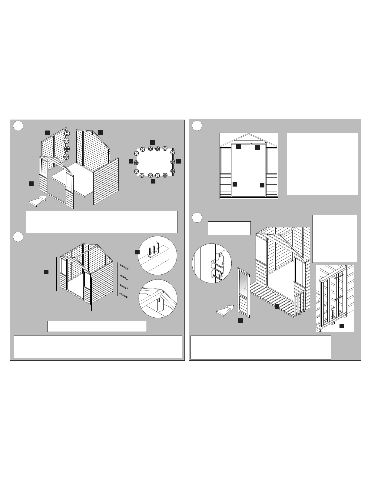
Fix two hinges to each of the doors using the smaller plate of the hinge as shown and
(4.0 x 30mm) screws. Place the doors into the entrance and secure the other half of the
hinge to the entrance framework.
Make sure there is enough clearance around the doors so that they can move freely.
TOP VIEW
Fix a corner brace to each end of the 1508 batten (N) on the 28mm side. Make sure that it is positioned as
shown and is 35mm from the end. Fix in place using 2 x (3.5 x 30mm) screws for each.
Place the batten at the apex so that it sits on the blocks on the front and back panel. Use 2 x (3.5 x 30mm)
screws to secure each of the corner braces to the blocks.
Place the panels on to the floor (D) as shown making sure that they are tight and flush. Fix the
panels to each other using 4x50mm screws for each join.
Make sure that all four sides are square and fix them to the floor using 50mm screws. Use
4x50mm screws for the door end (A) and Plain end (B). Use 3x50mm screws for the sides (C)
Place each of the 1710mm strips (Q) against the corners of the
building. Fix each in place using 4 x (3.5 x 30mm) screws.
Position the veranda (E)
against the front of the
building, the cladded only.
From inside the building fix the two 1785mm
strips (T) to the sides of the door, lining
them up so that they are flush on one side
and overhang the entrance slightly.
Fix each using 3 x (3.5 x 30mm) screws.
Place the strips (U) and (V) above the
entrance as shown, again lining these up
with the top of the framework. There should
be a 46mm gap between the two strips.
Fix each in place using 2 x (3.5 x 30mm)
screws.
E
Place a handrail section
(H) on the floor so that
it is tight against the
door end and flush with
the outside. Fix this to
the door end using 2 x
60mm screws. Further
secure this by fastening
it to the veranda using
2 x 50mm screws
H
F

ISSUE 0414
5
W
W
F
Fix both of the 800mm strips (W) to the inside of door (F) so they are flush with the top and
bottom of the door and overhang the side by 20mm. Fix each strip in place using 2 x (3.5 x
30mm) screws.
Fix a shoot bolt to the top and bottom of the door. Fix the receiver to the framework between
the two strips as illustrated. Use the 20mm black screws provided.
Still from inside the building line the lock up with the key hole in the door and fix using the 4 x
32mm black screws.
6
8
Forest Garden Ltd. Unit 288 Hartlebury Trading Estate, Hartlebury, Worcestershire, DY10 4JB
380mm
G
L
O
J
Place the roof sheet (J) on to a 2070mm batten (O) so that it sits on to the wider face and is
flush with the sides. Fix using 6 x (3.5 x 30mm) screws spaced evenly.
fix one of the 150mm blocks (L) so this is flush with the roof sheet but is 380mm apart from
the batten. Fix using 2 x (3.5 x 30mm screws).
Repeat this for the other roof to make a left and right hand roof section.
From outside of your
building fix a turn
button to the top and
bottom of the left hand
door using 2 x (4.0 x
30mm zinc) screws.
Make sure that the
turn button will reach
across both doors
when in its closed
position.
Place a 1732mm angled post
(M) against the end of the
handrail so that the pitch of the
angle is towards the apex. Fix
this in place using a corner
bracket. Use 2 x 50mm screws
to secure each bracket to the
floor and 2 x (3.5 x 30mm
screws) to secure this to the
post.
Further secure the post to rails
using 2 x 50mm screws.
E
7
S
I
Place the window (I) into the door end so that there is an equal gap each side before placing
an 848mm (S) (rebated) batten on either side. The rebate should sit against the window.
Fix each batten in place using 3 x 50mm screws screwing into the door ends framework.
H
M

9
Position the remaining 150mm battens (K) against the inside of the roof so that it is
tight against the veranda post (approximately 116mm). Fix the block to the roof
using 2 x (3.5 x 30mm) screws, screwing down through the roof.
Fix the veranda post (M) to the block using 1 x 50mm screw.
116mm
S
10
11
Mark and position
a handle on to
each of the doors.
Fix each using
the 4 x 20mm
screws provided.
Place a finial (K) over
the join of both barge
boards at the apex.
Fix each in place using
2 x (3.5 x 30mm
screws)
Place each of the
barge boards (P) so
that they are in line
with the top of the roof
and overhang the
eaves by 32mm. Fix
each barge board in
place using 3 x (3.5 x
30mm screws).
Trim off any excess
felt that sticks out
below the boards.
ATTENTION:
TAKE CARE
WHEN TRIMMING
THE ROOF FELT.
Place the 300mm angled block
(S) underneath the two roof
sections at the front of the apex.
Fix this in place screwing
through each roof in to the block
using 2 x (3.5 x 30mm) screws.
Place the roof sections on to the building so that the smaller 150mm blocks are at the
front and the roof is flush at the back. Use 4 x 40mm screws to secure the roof to the
side panels and 6 x (3.5 x 30mm) screws to secure the roof section to the front and
back panels.
Fix the roof section to the top of the 1508mm batten (N) with a single 50mm screw.
Place two pieces of the felt on
the lower sections of the roof.
Make sure these are
positioned centrally and have
an overhang of approximately
50mm. Secure each piece in
place using felt nails spaced
in 150mm intervals.
Place the third sheet of felt
over the top of the apex so
that it overlaps the other two
sections. Again secure this in
place using felt nails spaced
in 150mm intervals.
Biocidal Product Regulation
(EU 528/2012) Article 58
Information
This article contains timber
treated with Celcure AC-500,
incorporating biocidal products to
give protection against wood
destroying insects & wood rotting
fungi.
Contains: Basic copper carbonate
(Copper (II) carbonate – Copper
(II) hydroxide (1:1)), Boric acid,
Benzalkonium chloride.
Wear gloves when handling
freshly treated wood. Avoid
breathing dust when cutting
treated or untreated wood.
Dispose of off-cuts responsibly –
do not burn.
Maintenance.
- Regularly check all fixings and
parts are secure.
- Visually check for wear and tear.
- Check your roof felt for tears and
leaks.
I
P
K
P
Popular Other manuals by other brands

Stihl
Stihl FS 310 instruction manual

Elaflex
Elaflex ZVA 25 Installation and operating information

Metra Electronics
Metra Electronics AX-ADGM03 installation instructions

Thomas Industries
Thomas Industries Rietschle Thomas SK2660 manual

REVERSO-MANUFACTURING
REVERSO-MANUFACTURING DVF200 N/TV Installation and operating instructions

Westinghouse
Westinghouse CVR-1 instructions


