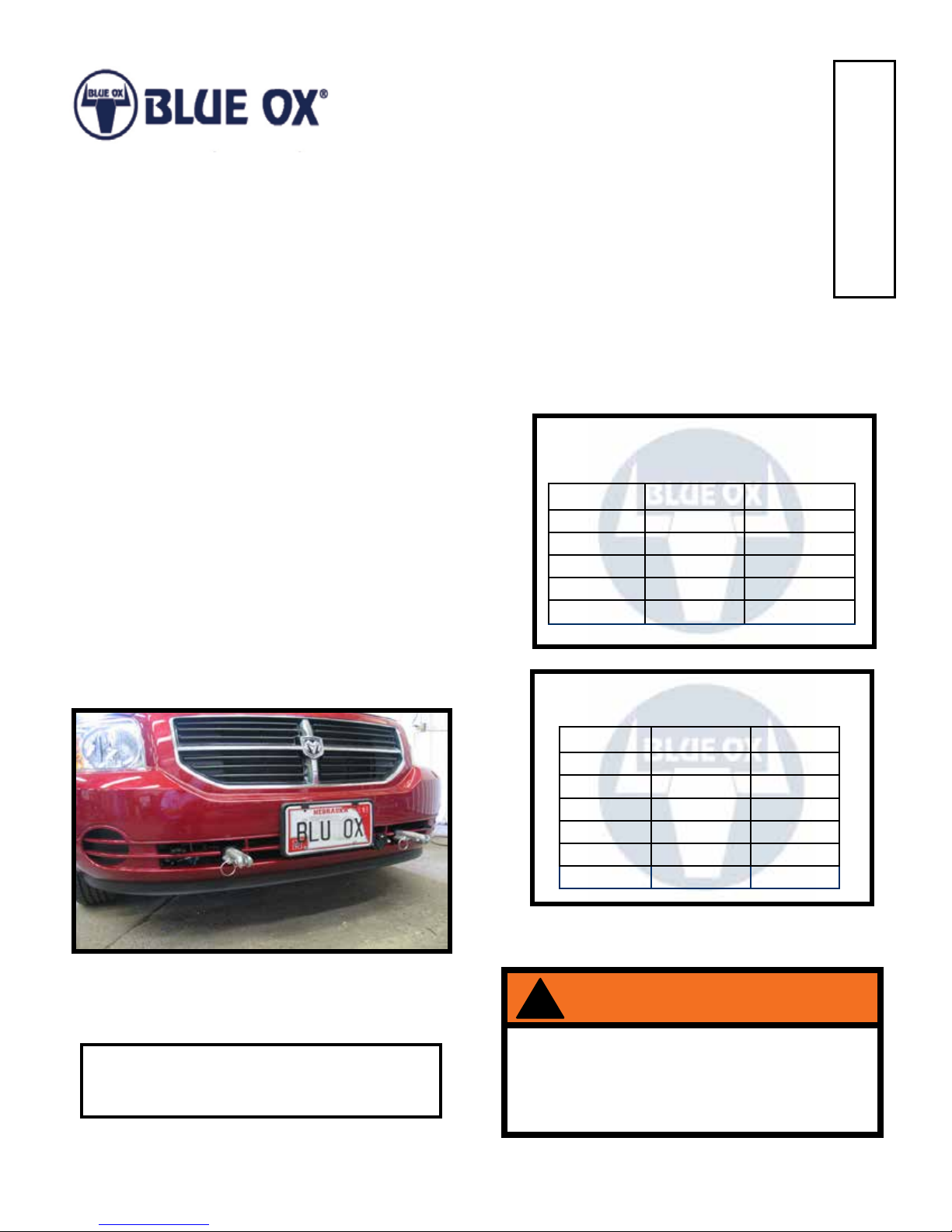
Blue Ox BX1975 Service manual

BX1975
2007-12 Dodge Caliber (No SRT)
Installation Instructions
292-2883 Rev F Page 1 of 9 4/8/13
Please read BOTH these Installation Instructions and the General Instructions prior to
installing or operating this equipment.
1. Blue Ox®towing products and accessories are
intended to be installed by Blue Ox® Dealers
who are familiar with our products and have the
equipment and knowledge necessary to do “t
work”. If needed, Blue Ox®Dealers can be found
at www.blueox.com or by contacting our Customer
Care Department at (402) 385-3051.
2. Many Blue Ox®baseplates are designed to
use existing holes and hardware to mount the
baseplate to the towed vehicle. Even though bolts
are there, do not assume they are adequate for
baseplate mounting. Always use the hardware
supplied in the hardware kit and existing hardware
as specied in the installation instructions.
Reference your vehicle owner’s
manual for manufacturer’s towing
specications.
Attachment Tab Height: 15”
Attachment Tab Width: 24”
Bolt Size Grade 5 Grade 8
1/4” 10 14
5/16” 19 29
3/8” 33 47
7/16” 54 78
1/2” 78 119
5/8” 154 230
Bolt Torque Specications
Torque in Foot-Pounds for Inch Bolts
Bolt Torque Specications
Torque in Foot-Pounds for Metric Bolts
Bolt Size Grade 8.8 Grade 10.9
6MM 6 8
8MM 16 22
10MM 31 40
12MM 54 70
14MM 89 117
Serial Number
If the front of your vehicle looks different than
this, please contact us at (402)385-3051. !
Failure to read and follow these instructions
could result in separation of the towed vehicle
from the tow bar, causing property damage,
loss of towed vehicle, personal injury or death.
WARNING

BX1975
2007-12 Dodge Caliber (No SRT)
Installation Instructions
292-2883 Rev F Page 2 of 9 4/8/13
Instruction Notes: The fascia and horn are removed and reinstalled for the baseplate installation.
Some drilling and trimming is required.
Place all components that are removed on a at, sturdy surface. All items will be reinstalled unless
otherwise noted after the baseplate is installed.
The dimensional variations between otherwise identical vehicles can be considerable. While the
baseplate was designed for easy installation, it may be necessary to tailor the baseplate slightly to
compensate for vehicle manufacturer’s tolerances.
The BX8869 Tail Light Wiring Kit is recommended for this vehicle.
Drill a hole according to the tail
light wiring kit instructions.
NOTICE
• Handling of some cosmetic parts when installing this product may require the use of protective
covers, rags, specialty tools, etc. to prevent damage.
• When using power drills be aware of the dangers of torque and drill bit length.
• When using a reciprocating saw be aware of objects behind the cutting surface.
• Use a good quality paint to spray cut edges of frame to prevent rusting.
• Be sure that ALL electrical connections are plugged in and accessories are functioning properly
before reinstalling the fascia.
• Do not use the towed vehicle for storing luggage, equipment, etc. This may cause you to
exceed the towing capacity of the tow bar, baseplate and its accessories.
• Be sure to use Loctite®Red on all bolts before tightening. Tighten all bolts according to the
torque chart provided.
• Dealer or installer be certain the user receives these instruction sheet.
• If the baseplate is in an accident, it must be replaced. DO NOT use it again! An accident can
cause unseen damage and using it again could result in more damage or serious injury. DO NOT
use the baseplate if it is damaged or missing parts.

BX1975
2007-12 Dodge Caliber (No SRT)
Installation Instructions
292-2883 Rev F Page 3 of 9 4/8/13
Item No. Part No. Description Qty.
1.................................61-6316 .............................BX1975 Baseplate...........................................................1
2.................................61-5208 .............................3/8”-16 Nut Plate w/ 14” Wire ..........................................3
3.................................102-6753 ...........................BX1975 DS, Spacer Plate ...............................................1
4.................................201-0443 ...........................3/8”-16 x 1” Hex Head Bolt, Grade 5, ZP ........................2
5.................................201-0440 ...........................3/8”-16 x 1-1/2” Hex Head Bolt, Grade 5, ZP ..................4
6.................................201-0404 ...........................3/8”-16 x 1-3/4” Hex Head Bolt, Grade 5, ZP ..................2
7.................................203-0010 ...........................3/8” Lock Washer, ZP ......................................................8
8.................................202-0003 ...........................3/8”-16 Hex Nut, ZP.........................................................5
9.................................201-0553 ...........................1/4-20 x 1/2” Hex Wshd Bolt Type F TCS, ZP.................2
10...............................201-0192 ...........................#10-32 1/2” Round Slotted Head Screw..........................2
11 ...............................203-0054 ...........................#10 Lock Washer, ZP ......................................................2
12...............................202-0047 ...........................#10-32 Hex Nut ...............................................................2
13...............................101-5822 ...........................4 Way Connector Adapter ...............................................2
14...............................62-3468 .............................Attachment Tab Assembly with Hole ...............................2
15...............................226-0046(not shown) ........Class III Safety Cables ....................................................2
16...............................229-0359(not shown) ........3/8” Quicklink, ZP ............................................................2
17...............................290-0437(not shown) ........Black Cap Plug Receiver.................................................2
Tools Required
Large Vise Grip
Flat Screwdriver
Utility Knife
Phillips Screwdriver
Torque Wrench
Drill
Reciprocating Saw
Tape Measure
Loctite®RED
13/32” Drill Bit
1-1/4” Hole Saw
7MM Socket
10MM Socket
13MM Socket
9/16” Socket
9/16” Wrench
T30 Torx
Important:
Use only genuine factory replacement parts on your baseplate. Do NOT substitute homemade or non-typical parts. If a bolt is lost or in need of
replacement, for your safety and the preservation of your baseplate, be sure to use a replacement bolt of the same grade (In most cases it will be Grade
5, please reference the parts list above). Replacement parts may be ordered through your nearest Blue Ox® Dealer or Distributor. Failing to follow and/
or altering these installation instructions in either installation or required equipment will void the manufacturer’s warranty. Towing behind a non-motorized
vehicle will void the warranty.

BX1975
2007-12 Dodge Caliber (No SRT)
Installation Instructions
292-2883 Rev F Page 4 of 9 4/8/13
1. Using a T30 Torx, remove the three (3)
screws from the top edge of the fascia. Do
this on both sides of the vehicle.
2. Using a 7MM socket, remove the two (2)
screws from the wheel well (white). Then
the push pin on the lower corner (gray).
Do this on both sides of the vehicle.
3. Behind the wheel well cover, using a 7MM
socket, remove the screws from the top
edge of the fascia. Do this on both sides
of the vehicle.
4. Remove the two (2) push pins from the
underside corner of the fascia. Do this on
both sides of the vehicle.

BX1975
2007-12 Dodge Caliber (No SRT)
Installation Instructions
292-2883 Rev F Page 5 of 9 4/8/13
5. Remove the four (4) push pins from the
underside edge of the fascia. Do this on
both sides of the vehicle. Remove the
fascia from the vehicle.
6. Using a 10MM socket, remove the two (2)
bolts from the coolant line brackets.
7. On the passenger side, pry the coolant
line clips away from the frame to allow
clearance for cutting.
8. On the driver side, disconnect the sensor
wire from the side of the frame and bottom
of the bumper to allow clearance for
cutting.

BX1975
2007-12 Dodge Caliber (No SRT)
Installation Instructions
292-2883 Rev F Page 6 of 9 4/8/13
10. On the driver side, disconnect the horn
wire (left). Using a 10MM socket, remove
the bolt from the horn bracket (middle).
Then using a 13MM socket, remove the
bolt from the wiring harness (right).
9. On the driver side, using a 13MM socket,
remove the bolt from the wiring harness.
11. Using a reciprocating saw, trim the end of the
bumper off so that it is ush with the frame.
Do this on both sides of the vehicle.
12. Using a reciprocating saw, trim the web
3/4” up from the tab back to the frame.
Then down ush with the frame. Do this
on both sides of the vehicle.
3/4”
13. Using a 1-1/4” holesaw, drill an access
hole on the face of the frame above the
bumper. Do this on both sides of the
vehicle.

BX1975
2007-12 Dodge Caliber (No SRT)
Installation Instructions
292-2883 Rev F Page 7 of 9 4/8/13
14. Install the baseplate onto the vehicle,
pushing the driver side up to the rear frame
webbing (gray). Level the baseplate and
clamp in place. The top of the baseplate
crosstube should be approximately 1/4”
from the bottom of the bumper. Using a
13/32” drill bit, drill the front hole of the
baseplate thru the frame. Do this on both
sides of the vehicle. On the driver side
install a 3/8”-16 x 1-1/2” bolt with 3/8” lock
washer and a 3/8”-16 nut (white). On the
passenger side install a 3/8”-16 x 1” bolt
with 3/8” lock washer and 3/8”-16 nut.
Tighten all fasteners.
15. On the driver side, using a 13/32” drill bit,
drill the remaining three (3) holes thru the
frame. On the lower middle hole, insert
the spacer in between the frame and
baseplate and install a 3/8”-16 x 1-3/4”
bolt with 3/8” lock washer and 3/8”-16” nut
(black). Install a 3/8”-16 x 1-1/2” bolt with
3/8” lock washer and 3/8” nut plate into
each of the rear holes, using the access
hole in front for the nut plates. Tighten all
fasteners.
16. On the passenger side, using a 13/32” drill
bit, drill the remaining three (3) holes thru the
frame. On the lower middle hole, install a 3/8”-
16 x 1” bolt with 3/8” lock washer and 3/8”-16”
nut (black). Install a 3/8”-16 x 1-1/2” bolt with
3/8” lock washer and 3/8”-16 nut plate into
the upper rear hole (white). Install a 3/8”-16 x
1-3/4” bolt with 3/8” lock washer and 3/8”-16
nut plate (gray), using the access hole in front
for the nut plates. Tighten all fasteners.

BX1975
2007-12 Dodge Caliber (No SRT)
Installation Instructions
292-2883 Rev F Page 8 of 9 4/8/13
17. On the passenger side, insert the back
coolant line clip into the baseplate hole.
Insert the front clip back into the existing
hole. Reinstall the bolts back into the front
brackets of the coolant line.
18. Attach the permanent baseplate safety
cables to the provided convenience link on
the baseplate. The photo above shows the
recommended installation of the cables to
frame of vehicle. Additional options may
interfere with suggested mounting; in this
case, secure the cables to a solid piece of
the frame as described in the instructions
included with the permanent baseplate safety
cables. Be sure the safety cables do not rub
against any hoses or moving parts. Do this
on BOTH sides of the vehicle.
19. Reinstall the wiring harness bolts and
horn. On the backside of the fascia,
remove the platice panels (inset). Hold
the fascia as close to its original position,
mark and trim around the attachment tabs.
Reinstall the fascia.

BX1975
2007-12 Dodge Caliber (No SRT)
Installation Instructions
292-2883 Rev F Page 9 of 9 4/8/13
CUSTOMER SERVICE COMMITMENT
Blue Ox® is committed to providing you with exceptional customer care throughout your lifetime
with our products. Our team is here to assist you with any questions you may have regarding the
performance of your product. Simply call (402) 385-3051 and you can speak with our customer care
team.
Additionally, please visit our website to see which rallies our Destination America team will be
attending. For a nominal fee, our service technician will service your towing system to ensure it’s in
proper working condition. Also, as a commitment to our customers, should you visit our factory, you
can stay at our full service Blue Ox® campground at no charge along with enjoying a factory tour.
Again, thank you for being our customer and for the condence you have shown in the performance
of our products. It is because of customers like you we enjoy the success we have today.
© 2012 Blue Ox
One Mill Road, Industrial Park
Pender, Nebraska 68047
Phone: (402) 385-3051
Fax: (402) 385-3360
www.blueox.com
Shown without removable tabs installed. Shown with removable tabs installed.
Other Blue Ox Other manuals

Blue Ox
Blue Ox BX3763 User manual

Blue Ox
Blue Ox BX3612 User manual

Blue Ox
Blue Ox BX2635 User manual

Blue Ox
Blue Ox BX2164 User manual

Blue Ox
Blue Ox BX1508 User manual

Blue Ox
Blue Ox BX1625 User manual

Blue Ox
Blue Ox BX2654 User manual

Blue Ox
Blue Ox BX1119 User manual

Blue Ox
Blue Ox AMBASSADOR BX7302 User manual
Popular Other manuals by other brands

BINZEL-ABICOR
BINZEL-ABICOR BRS-CC operating instructions

istobal
istobal Twash 4TA6000 CIVIL WORK AND INSTALLATION

JUWEL Aquarium
JUWEL Aquarium Monolux instruction manual

Paradyne
Paradyne 9161 Single T1 reference guide

Leuze electronic
Leuze electronic MSI-SR4B manual

Greijmans
Greijmans MVT-390 user manual