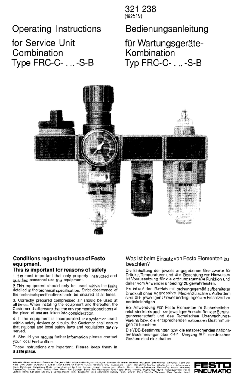
Thomas Industries Rietschle Thomas SK2660 User manual

MODEL SK2660
COMPRESSOR SERVICE KIT
For use on 2660 and 2680 Model Compressors
CAUTION: Improper assembly or use of damaged parts may lead
to premature failure. To avoid frequent repairs follow the recom-
mended assembly procedures.
Part No.642648A 0605
NOTE: Before you begin, read these instructions thoroughly and
assemble the necessary tools. You will need:
1/4” Hex Socket attachment for torque wrench
Torx T-27 attachment for torque wrench (for retainer screws)
Torx T-25 attachment for torque wrench (for head screws)
5/32” Allen® wrench for torque wrench (eccentric screw)
Flat Screwdriver (2)
Clean Cloths
WARNING: Unplug the compressor before beginning disassembly.
This kit includes the following parts:
NOTE: All parts in kit may not apply to your specific model.
625175 Head Screw (8)
625776 Screw-Piston Cup (2)
618114 Cylinder Sleeve (2)
625094 Flapper Screw (4)
624677 Piston Cup (2)
623143 Head Gasket (2)
623137 O-Ring (2)
621485 Valve Flapper (4)
617562 Valve Keeper (4)
A Thomas Industries Company
1419 Illinois Avenue
Sheboygan, Wisconsin 53082 USA
(920) 457-4831 www.rtpumps.com
621647 Valve Backer (4)
626392 Piston Cup Retainer(2)617177 Valve Restraint (2)

DISASSEMBLY
NOTE: To avoid confusion, service one end of the compressor at a time.
STEP 1. Clean loose dirt from the outside of the compressor.
STEP 2. Loosen the 8 head screws (1) and remove the compressor head (2). Note orientation
of head and valve plates for reassembly (very important). Discard head screws.
Caution: Place capacitor off to side leaving it connected to
lead wires.
STEP 3. Carefully remove the valve plates (4) from the bottom of the head, or cylinder
sleeves
STEP 4. Remove the head gasket O-rings (3) and discard them. Turn the valve plates over.
Remove the valve plate O-rings (5) and discard them. Note orientation for reassembly.
1
Figure 1
Caution
To avoid property damage
or personal injury, always
try rotating the fan by HAND
prior to connecting the
unit to the power source.
Check for suction at the air
inlet port by placing your
finger over the port as you
turn the fan. You should
feel a slight suction with
each rotation of the fan. If
you don’t feel suction, or if
you feel or hear a thump as
you turn the fan, DO NOT
CONNECT THE UNIT TO A
POWER SOURCE; review
the assembly procedure for
possible error.
Numbers indicate tightening sequence
Power Leads
Head Assembly
5 3 7 1
4 6 2 8
STEP 2. Place head on the valve plates, making sure the same letter orientation is
as it was before disassembly. Torque the head screws to 55 inch lbs. in a criss-cross
pattern.
STEP 3. Push the fan guards into the housing until the release tabs “pop” into the
mounting holes in the compressor housing.
6
Note the tabs on
the valve plate
which indicate
exhaust side.

STEP 5. Remove the intake valve flapper
(1), keeper (2), restraint (3) if assembled,
and screw from the bottom of the valve plate
and discard. Clean the bottom of the plate
with a clean, soft cloth. Install the new intake
valve flapper, restraint, if one was removed,
and keeper. The valve keeper should be
placed on top of the flapper so that the word
“UP” is visible (See Fig. #2).
NOTE: Pay close attention to valve
assembly. Some parts in kit may not be for
your model.
NOTE: Torque new flapper screw to 18
inch-pounds.
STEP 6. Install the new O-ring, seating it
firmly into the groove with your finger or
blunt object. (See Fig. #2).
Figure 2
Figure 3
STEP 7. Remove the exhaust valve flapper
(1), restraint (2) and valve keeper (3)from
the top of the valve plate and discard them.
Clean the top of the plate with a clean, soft
cloth. Install the new exhaust valve flapper,
restraint and keeper. The valve keeper
should be placed on top of the flapper so
that the word “UP” is visible (See Fig. #3).
NOTE: Torque flapper screw to 18 inch-
pounds.
STEP 8. Install the new head gasket,
seating it firmly into the groove with your
finger or blunt object. (See Fig. #3). Set
aside. Repeat steps 5 thru 8 to service other
end of compressor.
STEP 9. Remove the fan guard by depressing
the 4 tabs on the side of the housing.
STEP 10. Remove the fan by using two flat
blade screwdrivers to pry off, making sure
screwdriver contact is made with hub back,
and not the fan blades. Note fan orientation
for reassembly.
2
Figure 4
O-Ring Groove
O-Ring Groove
Release Tab
View of fan
with spring
clip facing in.
CAUTION: Make sure gasket
is not twisted when seated in
groove.
REASSEMBLY
STEP 1. With the sleeves firmly seated on the housing, replace the valve plates
in same manner as they were. (See Fig. #8). Make sure the top edge of the
sleeve locates in the O-ring groove in the bottom of the valve plate.
Figure 8
5
1 2
3
1
3
2

4
STEP 14. Rotate the rotor shaft so that flat faces up (12:00). Position piston cup at bot-
tom dead center of cylinder sleeve.
STEP 15. Slide the connecting rod assembly onto the shaft until the eccentric face
positivly stops against the bearing. Align the eccentric setscrew with the flat of the shaft.
Rotate the eccentric and shaft 90 degrees so the set screw is visable through the access
hole in the housing, and tighten set screw to 125in•lbs.
STEP 16. Align the flat on the fan with
the flat on the motor shaft and slide the
fan back onto the motor shaft, making
sure you position the fan clip in the
same orientation as it was before you
removed it. Incorrect orientation of the
fan will not provide adequate cooling of
the compressor.
Figure 7
Hold the sleeve down against the
housing with one hand, and slowly
rotate the fan with the other hand to
ensure all components are lined up
properly. As the piston travels up and
down it will also rock from side to side.
This is a feature of the WOB-L Piston.
Repeat steps 9-16 on the other side of
compressor.
STEP 11. Insert the 5/32” allen wrench into
the access hole in the compressor hous-
ing. Loosen the set screw 1/4 turn. Rotate
connecting rod to top dead center (180°)
and slide the connecting rod/eccentric
assembly off the shaft and through the
opening in the housing.
3
Eccentric
Set Screw
Access
Hole
Eccentric
Set Screw
Figure 5
STEP 12. Secure the rod assembly in a fixture.
Remove the sleeve (1 - discard) from the con-
necting rod. Remove the screw (2 - discard )
from the cup retainer (3-retain for reassembly).
Remove the piston cup (4 - discard) and wipe
debris from the top of the connecting rod and
retainer with a clean damp cloth.
STEP 13. Carefully place new sleeve (1) over
connecting rod top. Place new cup (4) in center
of connecting rod top. Do not damage the cup.
Place retainer (3) on top of cup (counterbore
up), making sure that the cup inside diameter
is seated properly over retaining boss. Note
that the retainer has a locating boss that must
insert into rod top pilot. Drive new retainer screw
to 100 in•lbs. Carefully push sleeve up forming
the cup. Stop pushing the cylinder sleeve up
when the piston cup is positioned midway inside
the sleeve.
1
4
3
2
Figure 6
CHECK OPERATION

4
STEP 14. Rotate the rotor shaft so that flat faces up (12:00). Position piston cup at bot-
tom dead center of cylinder sleeve.
STEP 15. Slide the connecting rod assembly onto the shaft until the eccentric face
positivly stops against the bearing. Align the eccentric setscrew with the flat of the shaft.
Rotate the eccentric and shaft 90 degrees so the set screw is visable through the access
hole in the housing, and tighten set screw to 125in•lbs.
STEP 16. Align the flat on the fan with
the flat on the motor shaft and slide the
fan back onto the motor shaft, making
sure you position the fan clip in the
same orientation as it was before you
removed it. Incorrect orientation of the
fan will not provide adequate cooling of
the compressor.
Figure 7
Hold the sleeve down against the
housing with one hand, and slowly
rotate the fan with the other hand to
ensure all components are lined up
properly. As the piston travels up and
down it will also rock from side to side.
This is a feature of the WOB-L Piston.
Repeat steps 9-16 on the other side of
compressor.
STEP 11. Insert the 5/32” allen wrench into
the access hole in the compressor hous-
ing. Loosen the set screw 1/4 turn. Rotate
connecting rod to top dead center (180°)
and slide the connecting rod/eccentric
assembly off the shaft and through the
opening in the housing.
3
Eccentric
Set Screw
Access
Hole
Eccentric
Set Screw
Figure 5
STEP 12. Secure the rod assembly in a fixture.
Remove the sleeve (1 - discard) from the con-
necting rod. Remove the screw (2 - discard )
from the cup retainer (3-retain for reassembly).
Remove the piston cup (4 - discard) and wipe
debris from the top of the connecting rod and
retainer with a clean damp cloth.
STEP 13. Carefully place new sleeve (1) over
connecting rod top. Place new cup (4) in center
of connecting rod top. Do not damage the cup.
Place retainer (3) on top of cup (counterbore
up), making sure that the cup inside diameter
is seated properly over retaining boss. Note
that the retainer has a locating boss that must
insert into rod top pilot. Drive new retainer screw
to 100 in•lbs. Carefully push sleeve up forming
the cup. Stop pushing the cylinder sleeve up
when the piston cup is positioned midway inside
the sleeve.
1
4
3
2
Figure 6
CHECK OPERATION

STEP 5. Remove the intake valve flapper
(1), keeper (2), restraint (3) if assembled,
and screw from the bottom of the valve plate
and discard. Clean the bottom of the plate
with a clean, soft cloth. Install the new intake
valve flapper, restraint, if one was removed,
and keeper. The valve keeper should be
placed on top of the flapper so that the word
“UP” is visible (See Fig. #2).
NOTE: Pay close attention to valve
assembly. Some parts in kit may not be for
your model.
NOTE: Torque new flapper screw to 18
inch-pounds.
STEP 6. Install the new O-ring, seating it
firmly into the groove with your finger or
blunt object. (See Fig. #2).
Figure 2
Figure 3
STEP 7. Remove the exhaust valve flapper
(1), restraint (2) and valve keeper (3)from
the top of the valve plate and discard them.
Clean the top of the plate with a clean, soft
cloth. Install the new exhaust valve flapper,
restraint and keeper. The valve keeper
should be placed on top of the flapper so
that the word “UP” is visible (See Fig. #3).
NOTE: Torque flapper screw to 18 inch-
pounds.
STEP 8. Install the new head gasket,
seating it firmly into the groove with your
finger or blunt object. (See Fig. #3). Set
aside. Repeat steps 5 thru 8 to service other
end of compressor.
STEP 9. Remove the fan guard by depressing
the 4 tabs on the side of the housing.
STEP 10. Remove the fan by using two flat
blade screwdrivers to pry off, making sure
screwdriver contact is made with hub back,
and not the fan blades. Note fan orientation
for reassembly.
2
Figure 4
O-Ring Groove
O-Ring Groove
Release Tab
View of fan
with spring
clip facing in.
CAUTION: Make sure gasket
is not twisted when seated in
groove.
REASSEMBLY
STEP 1. With the sleeves firmly seated on the housing, replace the valve plates
in same manner as they were. (See Fig. #8). Make sure the top edge of the
sleeve locates in the O-ring groove in the bottom of the valve plate.
Figure 8
5
1 2
3
1
3
2

DISASSEMBLY
NOTE: To avoid confusion, service one end of the compressor at a time.
STEP 1. Clean loose dirt from the outside of the compressor.
STEP 2. Loosen the 8 head screws (1) and remove the compressor head (2). Note orientation
of head and valve plates for reassembly (very important). Discard head screws.
Caution: Place capacitor off to side leaving it connected to
lead wires.
STEP 3. Carefully remove the valve plates (4) from the bottom of the head, or cylinder
sleeves
STEP 4. Remove the head gasket O-rings (3) and discard them. Turn the valve plates over.
Remove the valve plate O-rings (5) and discard them. Note orientation for reassembly.
1
Figure 1
Caution
To avoid property damage
or personal injury, always
try rotating the fan by HAND
prior to connecting the
unit to the power source.
Check for suction at the air
inlet port by placing your
finger over the port as you
turn the fan. You should
feel a slight suction with
each rotation of the fan. If
you don’t feel suction, or if
you feel or hear a thump as
you turn the fan, DO NOT
CONNECT THE UNIT TO A
POWER SOURCE; review
the assembly procedure for
possible error.
Numbers indicate tightening sequence
Power Leads
Head Assembly
5 3 7 1
4 6 2 8
STEP 2. Place head on the valve plates, making sure the same letter orientation is
as it was before disassembly. Torque the head screws to 55 inch lbs. in a criss-cross
pattern.
STEP 3. Push the fan guards into the housing until the release tabs “pop” into the
mounting holes in the compressor housing.
6
Note the tabs on
the valve plate
which indicate
exhaust side.

MODEL SK2660
COMPRESSOR SERVICE KIT
For use on 2660 and 2680 Model Compressors
CAUTION: Improper assembly or use of damaged parts may lead
to premature failure. To avoid frequent repairs follow the recom-
mended assembly procedures.
Part No.642648A 0605
NOTE: Before you begin, read these instructions thoroughly and
assemble the necessary tools. You will need:
1/4” Hex Socket attachment for torque wrench
Torx T-27 attachment for torque wrench (for retainer screws)
Torx T-25 attachment for torque wrench (for head screws)
5/32” Allen® wrench for torque wrench (eccentric screw)
Flat Screwdriver (2)
Clean Cloths
WARNING: Unplug the compressor before beginning disassembly.
This kit includes the following parts:
NOTE: All parts in kit may not apply to your specific model.
625175 Head Screw (8)
625776 Screw-Piston Cup (2)
618114 Cylinder Sleeve (2)
625094 Flapper Screw (4)
624677 Piston Cup (2)
623143 Head Gasket (2)
623137 O-Ring (2)
621485 Valve Flapper (4)
617562 Valve Keeper (4)
A Thomas Industries Company
1419 Illinois Avenue
Sheboygan, Wisconsin 53082 USA
(920) 457-4831 www.rtpumps.com
621647 Valve Backer (4)
626392 Piston Cup Retainer(2)617177 Valve Restraint (2)
Table of contents
