Forest-Master ZERO BARROW User manual
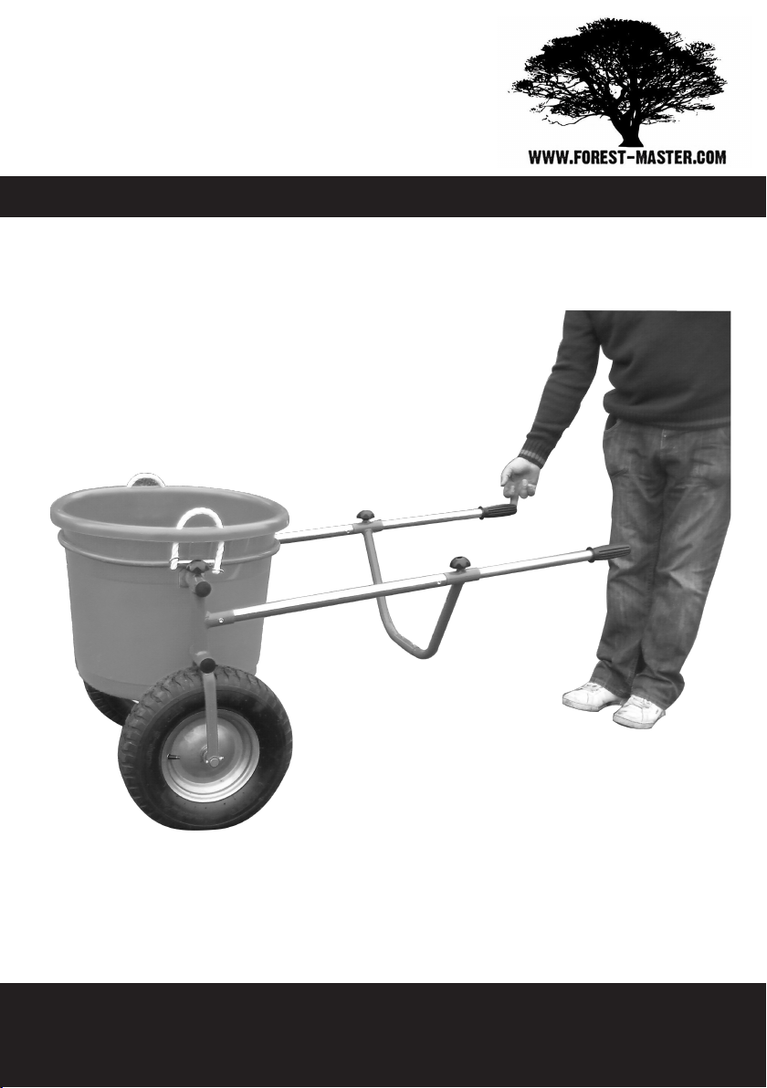
No Strain, Self Levelling Barrow
IMPORTANT: Read this manual fully before assembly
and use and observe all safety rules and operating
instructions
ZERO
BARROWPatented

Zero Barrow
Contents
Technical Specification 2
Exploded Diagram 3
Parts List 4
Assembly 5
Operation 11
Safety 14
Warranty 15
2
Technical Specification
Length 1400 mm 55 ins
Width 710 mm 28 ins
Height (excluding tub) 650 mm 26 ins
Weight (excluding tub) 14 kg 31 lbs
Wheel Size 4.80 / 4.00 x 8
Max Tyre Presure 2.0 bar 30 p.s.i.

Zero Barrow 3
Exploded Diagram
1234
5
17
16 6
7
8
9
10
11
12
13
14
15
18
2
9

Zero Barrow
Parts List
4
Item Description Qty
1 30 mm handle tube 2
2 M6 x 35 cap head bolt 4
3 M8 hand wheel 4
4 25 mm handle tube 2
5 Hand grip 2
6 Brace 2
7 Sleeve 1
8 M6 flange nut 6
9 M6 x 40 cap head bolt 2
10 Fork 2
11 M12 axle bolt 2
12 Wheel 2
13 M12 plain washer 6
14 Axle 1
15 M6 x 5 grub screw 2
16 Lifting ring front part 1
17 Lifting ring rear part 1
18 Self tapping screw 2
Assembly
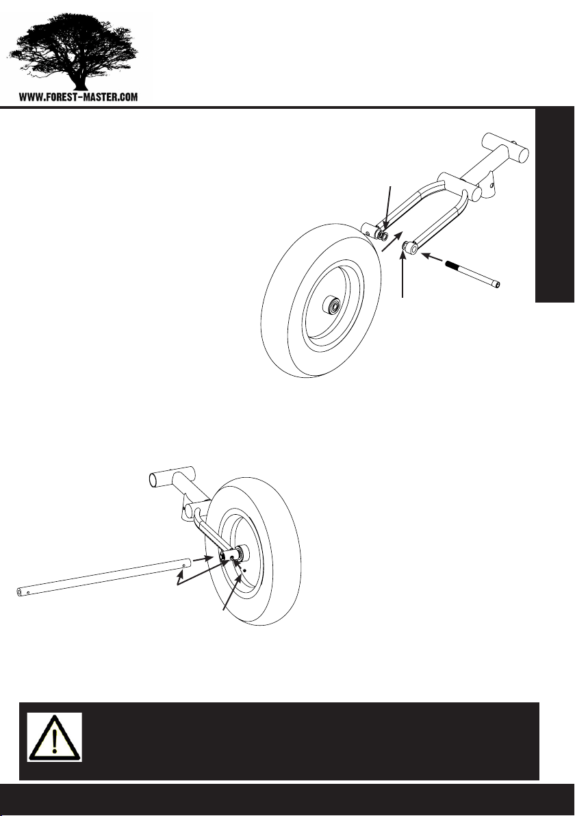
STEP 1:
Place a wheel (12) between
the legs of a fork (10). Insert
an axle bolt (11) through the
outside (narrower) guide and
through a plain washer (13)
placed between the outside
guide and the wheel. Locate
a second plain washer (13)
between the wheel and the
inside guide then insert
the axle bolt all the way
through. Note that the
outside guide is recessed so
that the bolt head is a flush
fit.
STEP 2:
Insert one end of the axle (14)
into the inner guide and locate
on the axle bolt. Screw in but
do not fully tighten the axle
bolt using an Allen key. Ensure
that the hole in the end of the
axle aligns with the hole in the
underside of the inner guide
then while holding the axle
steady, tighten the bolt.
PLAIN WASHER
PLAIN WASHER
ALIGN HOLES
GRUB SCREW
IMPORTANT: The barrow is supplied with 6 plain washers
as depending on the fit of the wheel, it may be necessary
to fit 2 washers on one side to space the wheel correctly.
Zero Barrow 5

Assembly
STEP 4:
Insert a 30 mm diameter han-
dle (1) into the locating tube
on the back of one of the forks.
Insert an M6 x 40 cap head
bolt (9) into the larger hole in
the outside of the locating tube
and through the locating tube
and the handle tube. Secure
with an M6 flange nut (8). Note
that the head of the cap head
bolt should sit inside the large
hole in the locating tube. See
note on Page 7.
STEP 3:
Repeat the procedure for the second wheel, ensuring that plain
washers are used each side of the wheel to correctly space it
and that the grub screw is correctly located and tightened.
LARGER HOLE
Zero Barrow6

Assembly
NOTE: One end of the 30 mm handle tube has two equal
diameter holes and the other has a large and small hole.
In Steps 4 & 5 you must insert the end with two equal di-
ameter holes into the mount on the fork. In addition, the
larger of the two holes at the other end should be orient-
ed to the outside of the handle.
STEP 5:
Repeat for the other 30 mm
handle tube and fork.
STEP 6
Insert each of the 25 mm
diameter handle tubes (4)
into a 30 mm diameter
handle and secure with
an M6 x 35 mm cap head
bolt (2) and an M6 nut (8).
Note that the head of the
bolt should sit inside the
larger hole in the 30 mm
handle tube.
Zero Barrow 7

Assembly
STEP 8:
Slide the brace top tubes
over both 25 mm handle
tubes so that the brace
rests against the ends of
the 30 mm handle tubes.
Insert an M8 handwheel (3)
into the nut on top of each
brace top tube and tighten
to secure the brace.
STEP 7:
Insert a brace (6) into
one end of the sleeve (7)
and secure with an M6
x 35 cap head bolt (2)
and M6 nut (8). Note the
larger diameter holes
in the sleeve should be
uppermost and the head
of the bolt should sit in
the large hole. Repeat for
the second brace.
LARGE HOLE
Zero Barrow8

Assembly
STEP 9:
If your barrow was purchased
without a tub or the tub was
packaged separately then it
will be necessary to join the
two halves of the lifting ring.
Insert the ends of the ring
half (17) into the connecting
tubes of ring half (16) and
secure with the self tapping
screws (18). The ends of the
half ring (17) are pre-drilled
for the screws.
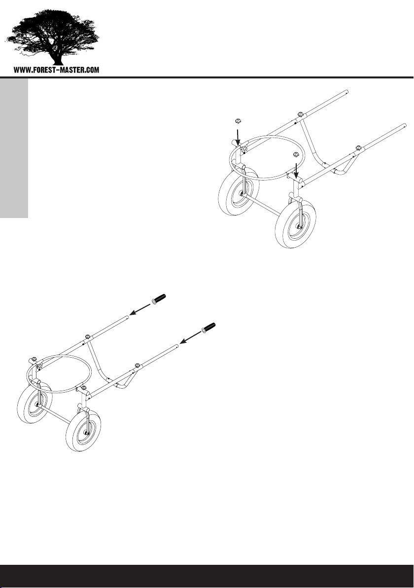
STEP 10:
Insert one of the lifting
ring pivot tubes into one
of the fork top tubes then
compress the ring and
insert the opposite pivot
tube into the opposite
fork top tube.
Zero Barrow 9
Zero Barrow
Assembly
10
STEP 11:
Screw the two remaining M8
handwheels (3) into the nuts
on the top of the fork top
tubes but do not tighten.
STEP 12:
Push a handgrip (5) over
the end of each of the 25
mm handle tubes. Ensure
they are fully located on the
handles.

Zero Barrow 11
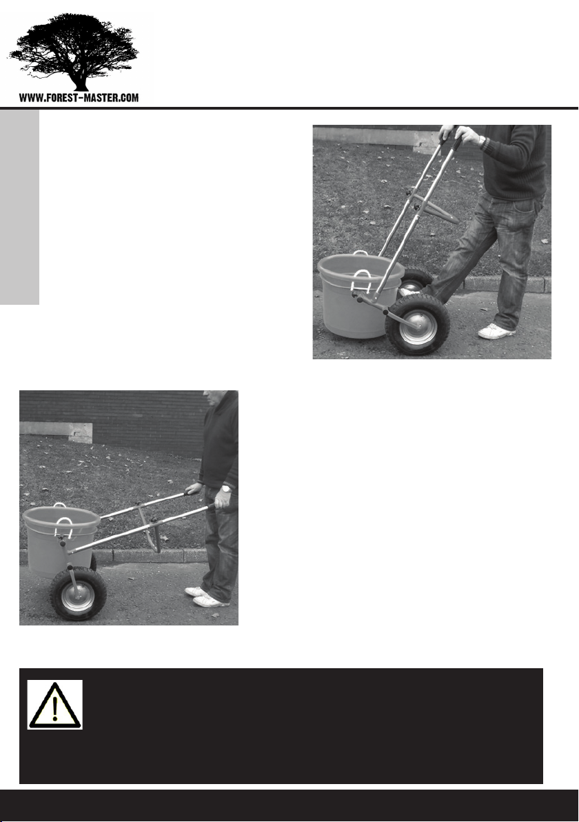
Operation
STEP 2:
Drag or lift the tub over the
front of the ring so it sits
within the ring.
STEP 1:
Position the barrow behind
the tub with the handles
tipped forward so that the
ring sits on the ground.
NOTE: The M8 handwheels on top of the forks should be
loose so that the lifting ring is free to pivot.
Lifting a tub
Operation
12 Zero Barrow
Step 3:
Place a foot on the axle and
pull back on the handles.
Step 4:
Lower the handles so that
the tub is over the axle.
NOTE: To lower a tub to the ground, place a foot on the
axle and lift the handles up and forward to lower the ring
to the ground. It is important to place a foot on the axle
to avoid the barrow moving backwards into the user.
To remove the tub simply lift or drag it clear of the ring.
Zero Barrow 13
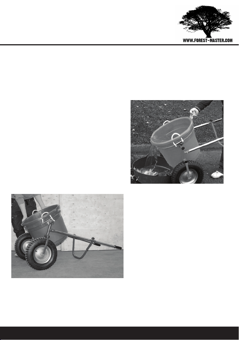
Emptying a Tub
It is possible to empty the tub without removing it from the
barrow, in a number of different ways depending on which is
most convenient to the user.
For lighter loads, the tub
can be tipped from behind
while still holding the bar-
row.
With heavier loads the
brace can be rested on the
ground and the tub tipped
from the side using two
hands.
It is also possible to tighten the hand wheels on top of the forks,
to stop the tub pivoting. The tub can then be emptied by raising
the handles as in a conventional barrow, this however is gener-
ally the least convenient.

Zero Barrow14
Safety
IMPORTANT SAFETY INFORMATION
Please read these instructions carefully. Note the safe oper-
ational requirements, warnings & cautions. Use the product
correctly and with care for the purpose for which it is intend-
ed. Failure to do so may cause damage and/or personal injury
and will invalidate the warranty. Please keep these instruc-
tions safe for future use.
Before using the barrow always check that all nuts and bolts
are secure and that the barrow is not damaged.
Check that the tyres are evenly inflated to a suitable pressure
for the load you are carrying. Do not exceed the maximum
pressure of 2.0 bar / 30 p.s.i.
Operation
Loading the Tub
Generally the tub is loaded on the ground ready positioned
within the ring or then lifted or dragged into the ring as
shown on Page 11. However the tub can be filled when already
raised in the ring. It is advisable when loading liquids this
way to lock the tub by tightening the handwheels however the
handwheels must be loosened before raising the handles.

Zero Barrow 15
Warranty
Warranty
This product carries a one (1) year limited warranty against
defects in workmanship and materials. Should this product
become defective within the stated warranty period, return it
to the store with proof of purchase, and it will be replaced or
repaired free of charge.
Should this product become defective, contact the store
where it was purchased and either replacement parts will be
issued, it will be repaired or it will be replaced free of charge.
IMPORTANT: NO RESPONSIBILITY IS ACCEPTED FOR
INCORRECT USE OF THIS PRODUCT.

Zero Barrow16
NOTE: It is our policy to continually improve products and as such
we reserve the right to alter data, specifications and component
parts without prior notice.
Manufactured under license for Forest Master Limited.
Registered Office:
Forest Master Ltd, Industry Road, Heaton, Newcastle Upon Tyne,
NE6 5XB, United Kingdom.
Tel: +44 191 2966939
Table of contents


