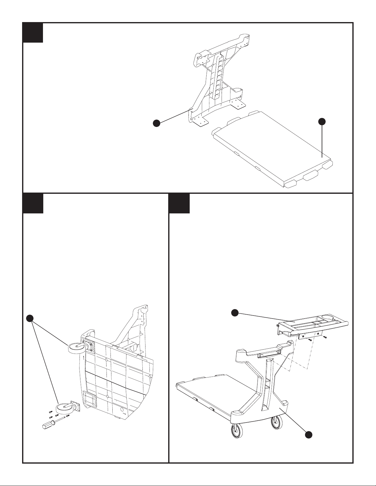
U-Line H-1495 User manual

Bin Utility Cart with Rail Kit
Model No. H-1495, H-1496, H-1497, H-1910
Assembly Instructions 800-295-5510 www.uline.com
TOOLS:
HERRAMIENTAS:
OUTILS :
BOTTOM GATE
REJILLA INFERIOR
GRILLE INFÉRIEURE
Hole, Orificio, Trou
Hook, Gancho, Trou
Tongue
Lengüeta, Languette
Rubber Mallet
Mazo de goma
Maillet en caoutchouc
Goggles
Gafas
Lunettes de protection
Phillips Screwdriver
Destornillador Phillips
Tournevis Phillips
Instrucciones de ensamblaje
Modelo H-1495, H-1496, H-1497,
H-1910
Instructions d’assemblage
Modèle n° H-1495, H-1496, H-1497,
H-1910
PARTS:
PARTES:
PIÈCES:
1.25" SCREWS
TORNILLOS DE 3.17CM (1.25 PULGADAS)
VIS DE 3 CM (1,25 PO)
5" SWIVEL CASTER
RUEDA GIRATORIA DE 12.7 CM (5 PULGADAS)
ROULETTE PIVOTANTE DE 12,7 CM (5 PO)
5" FIXED CASTER
RUEDA FIJA DE 12.7 CM (5 PULGADAS)
ROULETTE FIXE DE 12,7 CM (5 PO)
A x 30 B x 2 C x 2 D x 2
E x 2 F x 1 G x 1
H x 1
R x 9
I x 1
J x 1
TOP GATE
REJILLA SUPERIOR
GRILLE SUPÉRIEURE
HANDLE
ASIDERA
POIGNÉE
TOP SHELF
ENTREPAÑO SUPERIOR
TABLETTE SUPÉRIEURE
RAIL
RIEL
RAIL
BOTTOM SHELF
ENTREPAÑO INFERIOR
TABLETTE INFÉRIEURE
K x 1
FRONT GATE
REJILLA FRONTAL
GRILLE AVANT
FRONT PANEL
PANEL FRONTAL
PANNEAU AVANT
BACK PANEL
PANEL POSTERIOR
PANNEAU ARRIÈRE

1
23
Slide tongues of bottom shelf (I) into back panel (K).
Deslice las lengüetas del entrepaño inferior (I) en el
panel posterior (K).
Glisser les languettes de la tablette inférieure (I) dans
le panneau arrière (K).
I
K
Turn cart on side, install four screws through each swivel
caster (B) into bottom of back panel (K) and up into
bottom shelf (I) as shown.
Voltee de lado al carrito, instale los cuatro tornillos a través
de cada rueda giratoria (B) en el fondo del panel posterior
(K) y hacia arriba en el entrepaño inferior (I) tal como se
muestra.
Retourner le chariot sur le côté. Installer les quatre vis au
travers de chaque roulette (B) au fond du panneau arrière
(K) et dans la tablette inférieure (I), tel qu’illustré.
BG
Place handle (G) on top of back panel (K) so that the screw holes on
handle tabs line up with holes on back panel (K). Install screws.
Coloque la asidera (G) sobre el panel posterior (K) de tal manera que los
orificios para los tornillos en las lengüetas de la asidera se alineen con los
orificios del panel posterior (K) Instale los tornillos.
Placer la poignée (G) sur le panneau arrière (K) de façon que les trous de
vis sur les onglets de la poignée soient alignés avec les trous sur le panneau
arrière (K). Installer les vis.
K
➭
➭

4a 4b
H
Insert tongues on one end of top shelf (H) into
slots on back panel as shown. Install
2 screws on each side as shown.
Inserte las lengüetas en un extremo del
entrepaño superior (H) en las ranuras del fondo
del panel posterior, tal como se muestra.
Insérer les languettes sur une extrémité de la
tablette supérieure (H) dans les fentes sous le
panneau arrière, tel qu’illustré. Installer 2 vis
de chaque côté, tel qu’illustré.
Install additional four screws through four tab holes
which are near the four screws just attached in step
4a. See drawing 4b.
Instale los cuatro tornillos adicionales a través de los
cuatro orificios próximos a los cuatro tornillos que fueron
instalados en el paso 4a. Vea el dibujo 4b.
Installer les quatre autres vis dans les trous près des
quatre vis installées à l’étape 4a. Voir illustration 4b.
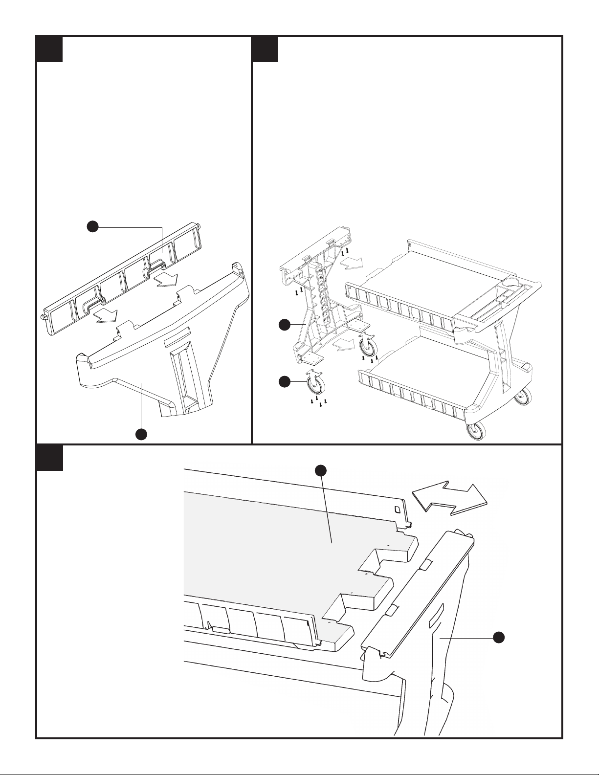
5
Stand cart up. Place the two top gates (D) onto the top shelf
(H) so that gate is in upright position and smooth side of gate
will face interior of cart. When placed correctly, the hook on
the cart handle will be through the hole in gate; the gate will be
resting on the support molded into the top shelf. Repeat this
process for two lower gates (E). Leave all gates in this upright
position for the rest of the assembly process.
Coloque parado el carrito. Coloque las dos rejillas
superiores (D) en el entrepaño superior (H) de tal manera
que la rejilla quede en posición vertical y la parte suave de
la rejilla mire hacia el interior del carrito. Cuando se coloca
adecuadamente, el gancho en la asidera del carrito, estará
pasando a través del orificio en la rejilla; la rejilla estará
metida en el soporte del entrepaño superior. Repita este
procedimiento para las dos rejillas inferiores (E) Deje todas
las rejillas en posición vertical durante el resto del proceso de
ensamble.
Relever le chariot. Mettre les deux grilles supérieures (D)
sur la tablette supérieure (H), de façon que la grille soit en
position verticale et que le côté lisse de la grille soit tourné
vers l’intérieur du chariot. Lorsque placé correctement, le
crochet sur la poignée du chariot traverse le trou de la grille;
cette dernière reposera sur le support moulé dans la tablette
supérieure. Répéter ce processus pour les deux grilles
inférieures (E). Laisser toutes les grilles en position verticale
jusqu’à ce que le montage soit terminé.
D
E
Gate Supports
Soportes de las rejillas
Supports de grille

Attach front gate (F) to front panel (J) by
sliding 2 hinges on front panel into front gate
as shown. Leave front gate in down position,
with the smooth side up, and resting on top
of the front panel.
Fije la rejilla frontal (F) al panel frontal (J) al deslizar
las dos bisagras del panel frontal en la rejilla frontal
tal como se muestra. Deje la rejilla frontal en posición
hacia abajo, descansando encima del panel frontal.
Fixer la grille avant (F) au panneau avant (J) en
glissant les 2 charnières sur le panneau avant dans
la grille avant, tel qu’illustré. Laisser la grille avant en
position abaissée, reposant sur le panneau avant.
Attach front panel (J) to top shelf (H) and bottom shelf (I) simultaneous-
ly by sliding shelf tongues into slots on front panel (J). Be sure to place
top and bottom gate tabs into holes on front panel. Attach fixed casters (C) to
bottom tabs of front panel and up into bottom shelf (I) as shown.
Fije el panel frontal (J) al entrepaño superior (H) y al entrepaño inferior (I)
simultáneamente al deslizar las lengüetas de los entrepaños en las ranuras del
panel frontal (J). Asegúrese de colocar las lengüetas de las rejillas superiores e
inferiores en los orificios del panel frontal. Fije las ruedas fijas (C) a las lengüetas
del fondo del panel frontal y hacia arriba del entrepaño inferior (I) tal como se
muestra.
Fixer le panneau avant (J) à la tablette supérieure (H) et à la tablette inférieure
(I) simultanément en glissant les languettes des tablettes dans les fentes sur
le panneau avant (J). Veiller à enfiler les onglets de la grille inférieure et de la
grille supérieure dans les trous sur le panneau avant. Fixer les roulettes fixes
(C) aux onglets inférieurs du panneau avant et dans la tablette inférieure (I), tel
qu’illustré.
67
F
C
J
J
J
HMaximum
Máximo
Maximum
2˝
Pull the top of front panel (J) no
more than 2 inches away from
top shelf.
Tire del tope del panel frontal (J)
no más de 2 pulgadas (5 cm)
alejándolo del entrepaño superior.
Tirer la partie supérieure du
panneau avant (J), pas plus que
2 pouces au-delà de la tablette
supérieure.
8

8
9
7
6
5
4
3
2
1
Beginning at bottom rail, slowly move front panel (J) back into position, making sure each rail (R) secures properly into slots on both
panels. You may need to alternately pull the front panel away from and push it towards the back panel to hold each
successive rail in place. If a rail falls out of position, simply place it back into its slot and continue.
Empezando con el riel del fondo, lentamente mueva el panel frontal (J) nuevamente a su posición, asegurándose que
cada riel (R) se asegura apropiadamente en las ranuras de ambos lados del panel. Usted podría necesitar de tirar alternadamente
el panel frontal lejos de y hacia el panel frontal para sostener cada riel sucesivo en sus sitios. Si un riel se sale de su posición,
simplemente colóquelo nuevamente en su ranura y continúe.
En commençant au bas du rail, remettre lentement le panneau avant (J) en place et s'assurer que chaque rail (R) se trouve bien
dans les fentes sur les deux panneaux. Il faudra peut-être alternativement éloigner le panneau avant du panneau arrière et le
repousser vers ce dernier pour mettre chaque rail en place. Si un rail est mal installé, il suffit de le remettre dans les fentes et de
continuer.
DO NOT TIP PROCART ON BACK PANEL FOR THIS STEP –YOU MAY
DAMAGE THE CART AND IT IS LIKELY THE RAILS WILL FALL OUT.
NO PONGA DE LADO EL PROCART SOBRE EL PANEL POSTERIOR
PARA ESTE PASO – PUEDE DAÑAR EL CARRITO Y ES POSIBLE QUE SE
CAIGAN LOS RIELES..
NE PAS POSITIONNER LE CHARIOT PROCART SUR LE PANNEAU
ARRIÈRE POUR CETTE ÉTAPE. –LE CHARIOT PEUT S'ABIMER ET IL EST
PROBABLE QUE LES RAILS TOMBERONT.
J
When all 9 rails are properly positioned, attach front panel (J) back to top shelf (H). Secure with screws. Your cart is now
equipped with the rail kit and is ready to use.
Cuando los 9 rieles estén colocados apropiadamente, fije el panel frontal (J) nuevamente en el entrepaño superior (H) Asegúrelo
con tornillos. Su el carrito está ahora equipado con su kit del riel y está listo para su uso.
Quand les 9 rails sont bien en place, accrocher de nouveau le panneau avant (J) à la tablette supérieure (H).
Fixer avec des vis. Votre chariot cart est désormais équipé de l'ensemble des rails et est prêt à être utilisé.
H
J
9
10
➭
➭

©2013 Akro-Mils/Myers Industries #AKM290UL 11/13
800-295-5510 www.uline.com
Capacity Capacidad Capacité
200
LB.
90
KG.
200
LB.
90
KG.
200 LB.
90 KG.
200
LB.
90
KG.
400
LB.
180
KG.
+=
200 LB.
90 KG.
Maximum
Máximo
Maximum
Maximum
Máximo
Maximum
CAUTION:
• EXCEEDING RECOMMENDED WEIGHT LIMIT MAY RESULT IN INSTABILITY CAUSING SERIOUS INJURY.
• MAXIMUM WEIGHT CAPACITY PER SHELF IS 200 lb. (90 kg).
• CAUTION WHEN MOVING CART ON INCLINE OR ROUGH SURFACE.
• CART CAN TIP OVER IF WEIGHT IS NOT EVENLY DISTRIBUTED.
• MAXIMUM PER CART LOAD IS 400 lb. (180 kg).
• US Patent Pending
PRECAUCION:
• EL EXCEDER EL LIMITE DE PESO RECOMENDADO PUEDE PROVOCAR NESTABILIDAD Y CAUSAR
LESIONES SERIAS.
• LA CAPACIDAD MÁXIMA DE PESO DE CADA ENTREPAÑO ES DE 200 lb. (90 kg).
• TENGA PRECAUCION CUANDO MUEVA EL CARRITO SOBRE SUPERFICIES INCLINADAS O RUGOSAS.
• EL CARRITO PUEDE VOLCARSE SI EL PESO NO SE ENCUENTRA DISTRIBUIDO DE MANERA
UNIFORME.
• LA CARGA MÁXIMA POR CARRITO ES DE 400 lb. (180 kg).
• Patente Pendiente en los EE.UU.
MISE EN GARDE:
• DÉPASSER LA LIMITE DE POIDS RECOMMANDÉE PEUT RENDRE LE CHARIOT INSTABLE ET
ENTRAÎNER UN RISQUE DE GRAVES BLESSURES.
• LA CAPACITÉ MAXIMALE DE LA PLATE-FORME EST DE 90 kg. (200 lb).
• USER DE PRUDENCE LORSQU’ON DÉPLACE LE CHARIOT SUR UNE PENTE OU SUR UNE SURFACE
INÉGALE.
• LE CHARIOT PEUT SE RENVERSER SI LE POIDS N’EST PAS RÉPARTI UNIFORMÉMENT.
• LE CHARGEMENT MAXIMAL PAR CHARIOT EST DE 180 kg. (400 lb).
• Brevet américain en instance
!
!
!
This manual suits for next models
3
Other U-Line Outdoor Cart manuals

U-Line
U-Line H-591 User manual

U-Line
U-Line H-10622 User manual

U-Line
U-Line H-9013 User manual

U-Line
U-Line H-4607 User manual

U-Line
U-Line H-2666 User manual

U-Line
U-Line H-1789 User manual

U-Line
U-Line RUBBERMAID H-1053 User manual

U-Line
U-Line H-3382 User manual

U-Line
U-Line H-1480 User manual

U-Line
U-Line H-2083 User manual

U-Line
U-Line H-5487 User manual

U-Line
U-Line H-2721 User manual

U-Line
U-Line H-1234 User manual

U-Line
U-Line H-1364 User manual

U-Line
U-Line H-9099 User manual

U-Line
U-Line H-8166 User manual

U-Line
U-Line H-5534 User manual

U-Line
U-Line H-2524 User manual

U-Line
U-Line H-2083 User manual

U-Line
U-Line H-5003 User manual