Formula Air RVA1-NX-06 User manual

User manual | RVA Rotary valves
www.formula-air. com
1
RVA Rotary valves
Maintenance manual (EN)

User manual | RVA Rotary valves
www.formula-air. com
2
Content
1. Introduction .................................................................................................................................................... 3
2. Product description......................................................................................................................................... 3
2.1 How it works ........................................................................................................................................... 4
2.1.1 Rotary valve body................................................................................................................................... 4
2.1.2 Rotor ...................................................................................................................................................... 4
2.1.3 Motor and Gearbox................................................................................................................................ 4
2.2 Overall dimensions.................................................................................................................................. 5
2.3 Technical datasheet ............................................................................................................................... 5
2.4 Electrical connection............................................................................................................................... 6
2.5 Precautions for proper use ...................................................................................................................... 6
2.6 Gearbox & Motor.................................................................................................................................... 6
3. Maintenance .................................................................................................................................................. 6
3.1 Periodic maintenance ............................................................................................................................. 6
3.2 Overhaul................................................................................................................................................. 6
3.3 Motor, gearbox & bearings..................................................................................................................... 6
3.3.1. Bearing Maintenance ............................................................................................................................ 6
3.3.2. Greasing interval ................................................................................................................................... 7
3.4 Replacing spare parts............................................................................................................................. 7
3.4.1 Rubber wear out.................................................................................................................................... 7
3.4.2 Replacing the rubber blades.................................................................................................................. 7
3.5 Noise level.............................................................................................................................................. 8
4. Components and spare parts.......................................................................................................................... 8
5. Rotation detector (optional)............................................................................................................................ 9
5.1 Placing the rotation detector ................................................................................................................. 9
5.2 Connecting the detector ...................................................................................................................... 11
6. Troubleshooting ............................................................................................................................................. 11
7. Dismantling and recycling.............................................................................................................................. 12
8. Maintenance log............................................................................................................................................ 13

User manual | RVA Rotary valves
www.formula-air. com
3
1. Introduction
This manual cannot be reproduced, even partially, without prior written consent by Formula Air Group. Every step of
the rotary valve all along its life cycle has been deeply analyzed by Formula Air Group in the expected area during
the design, construction, and manual creation. However, it is understood that nothing can replace the experience,
training and good sense of those professionals who work with the device.
Ignoring the cautions and warning from the present manual, using improperly parts or the whole device supplied, using
unauthorized spare parts, manipulating the device by non-qualified personnel, violation of any safety norm regarding
design, construction and use expected by the supplier, exempt Formula Air Group from all responsibility in case of
damages to people or properties.
Formula Air Group does not take any responsibility for the non-observance of the user about the preventive safety
measures presented in this manual.
The use implies compliance and knowledge of the Machine Directive 2006/42/EU.
Failure to comply with the requirements of the operating manual or incorrect use of the rotary valve during operation
can lead to the damage of the rotary valve and the loss of the proper function performed by the rotary valve itself.
This will result in termination of the warranty on the item and will release the manufacturer from any liability.
Warranty
Regarding to the device’s warranty, see the Sales General Conditions with your local Sales Office.
Attention
Before proceeding with the installation of the rotary valve, ensure that the markings on the product are compatible
with the rating of the site of use. Failure to comply with this prescription can cause serious injury to persons including
death and/or serious damage to property.
NOTE: All drawings and references contained within this manual are non-contractual and are subject to change
without prior notice at the discretion of the Formula Air Group and its partners.
Copyright © Formula Air.
The rotary valves are not designed to prevent the transmission of fire or burning powder transported by the normal
process flow.
The rotary valves are built in 3 mm thick steel, powder coated RAL 5010 and neoprene rubber.
2. Product description
Formula Air rotary valves fulfil all relevant requirement to be used under filters or cyclones. To accomplish this, several
instructions are described in this manual and shall be following prior to and during operation.
Note that besides the rotary valve, the complete installation needs to comply to :
2006/42/EU – Machine Directive
2014/35/EU – Low Voltage Equipment Directive
2014/30/EU – Electromagnetic Compatibility and Repealing Directive (EMC)
2014/68/EU – Pressure Equipment Directive

User manual | RVA Rotary valves
www.formula-air. com
4
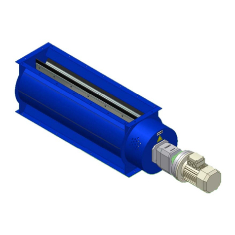
Figure 1. Formula Air rotary valve
2.1 How it works
The rotary valve is functionally built up of the following main components :
1. Rotary valve body
2. Rotor with rubber blades
3. Drive set (motor and gearbox)
Figure 2. Structural design
2.1.1 Rotary valve body
The rotary valve body is made of sheet steel. Inlet and outlet are foreseen with flange connection. The end plate
positioned at the drive set can be dismounted in a way that provides access to the rotor. The rotary valve body is
powder coated.
2.1.2 Rotor
The rotor is built up of a rotor shaft mounted with 6 sets of chambers. Neoprene rubber blades are mounted in the
blade retainers in the chambers.
2.1.3 Motor and Gearbox
The rotor is driven by an electric motor. The connection between rotor and electric motor is established by a gearbox.

User manual | RVA Rotary valves
www.formula-air. com
5
2.2 Overall dimensions
Type
A
(mm)
B
(mm)
C
(mm)
D
(mm)
E
(mm)
F
(mm)
G
(mm)
Mass
(kg)
RVA1-NX-06
250
316
150 (1x150)
68
286
418
782
48
RVA2-NX-06
500
566
450 (3x150)
43
536
494
1108
74
RVA3-NX-06
750
816
600 (4x150)
93
786
494
1359
91
RVA4-NX-06
1000
1066
900 (6x150)
68
1036
494
1609
107
RVA5-NX-06
1500
1566
1350 (9x150)
93
1536
494
2109
141
2.3 Technical datasheet
Installation, operation, maintenance, and repair may only be carried out by qualified personnel.
Ensure that no tools or foreign objects remain in the machine during assembly or maintenance.
Selection and installation of the electrical parts shall be fulfilled according the EN60079-14 and the installation
instructions of the specific equipment.
The airtightness of the rubber blade has to be controlled regularly according to the instructions in this user manual.
CAUTION!
The installation, connection, start-up and maintenance of the rotary valves have to be performed by qualified
personnel. Use the appropriate equipment and clothing, apply the necessary safety measures and do not work alone.
The rotary valve must not be started until it has been mechanically connected on both sides to other ducting
components by means of the built-in flanges.
The rotary valve must be sealed on both sides of the hole series and bolted in the predrilled holes.
It is mandatory to make sure that the whole installation is stopped and cannot be started-up again before everything
is connected and assembled.

User manual | RVA Rotary valves
www.formula-air. com
6
2.4 Electrical connection
Electrical connection must only be carried out by a certified electrician. When making the electrical
connection, check that the rotary valve rotor is turning in the correct direction. The rotation direction
is indicated by an arrow on the rotation disk cover.
The electrical connection must be carried out in accordance with current local and national
regulation.
2.5 Precautions for proper use
CAUTION!
It is strictly forbidden to open the rotary valve while the installation is running.
During functioning, the user has to ensure himself that there is no material stacking or material build-up inside the
rotary valve in order to ensure the proper discharge of the material.
During maintenance keep the system disconnected and all the electrical equipment turned off.
Avoid dust removal by blowing while cleaning.
2.6 Gearbox & Motor
For information on the installation of the gearbox and drive motors, see relevant manuals from the original
manufacturers (supplied separately).
Electrical parts shall be maintained according to manufacturer’s instructions and inspected periodically according to
local and national legislation (e.g. EN 60079-17).
IMPORTANT : Always wear the required safety equipment. The national safety rules in force must be observed.
3. Maintenance
3.1 Periodic maintenance
In order for the rotary valve to be guaranteed by the manufacturer, regular maintenance must be carried out by the
installer, manufacturer or a distributor appointed by the manufacturer.
Maintenance must always be carried out according to the instructions in the manual.
3.2 Overhaul
For the manufacturer’s guarantee to apply, the customer must have regular maintenance carried out by the installer,
manufacturer or a distributor appointed by the manufacturer.
For distributors to be approved to carry out maintenance for the manufacturer, they must be trained by the
manufacturer. The following must be checked: rubber blades, rotor, bearings, gearbox and motor.
NOTE : Rubber blades and sealing ring must be impermeable! Monitor wear regularly until service intervals can be
determined. Overhaul must minimum take place every 6 months.
3.3 Motor, gearbox & bearings
3.3.1. Bearing Maintenance
The lifespan of the grease is influenced by many factors. The greasing intervals in our table thus can only be seen as
very rough estimates.
Experience with comparable bearings or ones already used is therefore very important as not all operating conditions
and influential factors that affect the service life of a lubricant – and hence also the bearing – are known or
determinable in many cases.

User manual | RVA Rotary valves
www.formula-air. com
7
3.3.2. Greasing interval
Operating
temperature of
bearing °C
Greasing interval
Environmental conditions
Clean
Dirty
Very dirty
Heavily humid
50
3 years
6 months
3 months
70
1 year
2 months
1 month
100
3 months
2 weeks
1 week
For information on the maintenance of the gearbox and drive motors, see relevant manuals from the original
manufacturers (supplied separately).
3.4 Replacing spare parts
If the rubber blades are not impermeable or worn, they must be replaced. Visual inspection is carried out.
3.4.1 Rubber wear out
Rubber blades are worn out and must be replaced when dimension A and B are below optimal measurements in the
following table (See figure 4).
*
Figure 4. Rubber wear out
3.4.2 Replacing the rubber blades
CAUTION! Before any manipulation to the rotary valve, make sure that the motor is stopped and that all electrical
connections are disconnected.
NOTE : all electrical manipulations should be performed by qualified personnel only.
Step 1 : Unscrew the nuts and bolts holding the rubber blades.
Step 2 : Take the rubber blades out.
RVA size
A (mm)
B (mm)
RVA1
32
10
RVA2
38
10
RVA3
38
10
RVA4
38
10
RVA5
38
10

User manual | RVA Rotary valves
www.formula-air. com
8
Step 3 : Introduce the new rubber blades into the metal vane gap. Make sure that the holes are aligned, and the flap
is in the right direction then bolt them back.
3.5 Noise level
The noise ratio of the component in our scope of supply in connected condition and without media is below 70 dB (A)
measured at 1 meter from the component.
Noise from transported media is not included.
IMPORTANT!
A higher noise level may occur depending on local conditions, transported material and other components connected
to the rotary valve. In this case separate measurements may be required.
If the total noise level in the area exceeds 85 dB (A), hearing protection must be used.
4. Components and spare parts
Figure 8. Exploded view

User manual | RVA Rotary valves
www.formula-air. com
9
Spare parts
Code Description
JCAB000028
Bearing for RVA rotary valve (all models)
JCAB000001
Set of rubber blades (6 pcs) for RVA1
JCAB000002
Set of rubber blades (6 pcs) for RVA2
JCAB000003
Set of rubber blades (6 pcs) for RVA3
JCAB000004
Set of rubber blades (6 pcs) for RVA4
JCAB000005
Set of rubber blades (6 pcs) for RVA5
JCAB000027
Felt seals kit for all RVA rotary valve (2 seal rings)
JEBB000001
Gearbox for motor 0,37kW
JEBB000002
Gearbox for motor 0,55kW
JEAA000005
Motor - IE2 - 0,37kW - 4Pole - 230/400V - 50Hz
JEAA000006
Motor - IE2 - 0,55kW - 4Pole - 230/400V - 50Hz
JCAB000006
Rotor complete with rubber blades RVA1 – NX -06
JCAB000007
Rotor complete with rubber blades RVA2 - NX -06
JCAB000008
Rotor complete with rubber blades RVA3 - NX -06
JCAB000009
Rotor complete with rubber blades RVA4 - NX -06
JCAB000010
Rotor complete with rubber blades RVA5 - NX -06
5. Rotation detector (optional)
The optional rotation detector is a detection system that controls if the rotation disk is turning. In case of rotation
failure, it sends a signal to a control panel.
CAUTION! Before any manipulation to the rotary valve, make sure that the motor is stopped and that all electrical
connections are disconnected.
NOTE : all electrical manipulations should be performed by qualified personnel only.
5.1 Placing the rotation detector
Remove the rotation disk protection cover by untightening the bolts holding it on the rotary valve body.
Position
Description
Position
Description
1
Body
7
Motor and gear
2
Bearing housing
8
Bolt M5 x 10
3
Cover
9
Rotation detector
4
Rotation disc cover
10
Rotor and rubber blades
5
Detector holder
11
Bolts and washers M8
6
Rotation disc
12
Bolts, nuts & washers M8

User manual | RVA Rotary valves
www.formula-air. com
10
DU-6 detector ;
Attach the sensor through the inside of the sensor holder with the bolts and nuts delivered with the sensor.
M18 optical sensor :
Introduce the sensor in the hole on the top of the front of the over and tighten it in place with the nuts supplied with
the detector.
NOTE : make sure that the min/max distance between detector head and disk is respected as mentioned in the
supplier detector guide.
Place the rotation disc cover back in place by tightening the bolts holding it on the ATEX rotary valve body.

User manual | RVA Rotary valves
www.formula-air. com
11
5.2 Connecting the detector
CAUTION! Before any manipulation to the rotary valve, make sure that the motor is stopped and that all electrical
connections are disconnected.
NOTE : all electrical manipulations should be performed by qualified personnel only.
DU-6 connection : M18 optical connection :
6. Troubleshooting
Failure
Possible causes
Proposed solutions
Rotary valve
switches off
thermally
Foreign body got stuck
Rotor frozen
Gear motor defective
Rotor defective
Motor protection set incorrectly
Fuse defective
Big voltage drop in power supply
Remove foreign body
Thaw on the outside with hot air or water
Replace motor, or gearbox
Replace rotor
Adjust the motor protection
Replace fuse
Insure voltage consistency
Rotary valve
is not turning
Working switch is off
Motor protection switched of thermally
Conditions of operation are not met in the control
system
Fuse defective
It might be that something is stuck in the rotary valve
It might be that the motor or gearbox is broken
It might be that the motor or gearbox shaft key is
broken
Stop the installation, switch on the working
switch
See “Rotary valve switches off thermally”
Investigate why conditions are not met
Investigate that nothing is stuck in the rotor
Investigate if a part is broken and needs to
be replaced
Rotary valve
makes
“screaming”
noise
Foreign body got stuck
Rotor/rotary valve body is defective
The rotor turns the wrong way
Remove foreign body
Replace defective component
Wire the motor correctly
The material
will not pass
the valve
without
accumulation
Volume of material per rotation is larger than planned
Airflow opposite through the rotary valve presents
proper material flow
Settling velocity of material less than expected
The material accumulates in lumps which cannot pass
The material is not removed fast enough at the outlet of
the rotary valve
Transported material is too big/bulky
Material agglutinates
Reduce the volume of material feed, or
replace rotary valve
More frequent regeneration
Shorter step-interval of chain conveyor
Adjust the production machine to change
the flow of material
Check the proper functioning of the
emptying system
Use the adequate rotary valve
Rotation disk
doesn’t’ turn
but rotor
does
Rotation disk and rotor axle are no longer consolidated Tighten rotation disk on rotor axle
Rotation
detector
doesn’t react
Cable is not connected
Improperly connected cables
Detection distance is too big or too short
Make sure cables are connected
Insure proper cable connection
Verify installation distance
If the problem persist, contact the installer or manufacturer.
NAMUR NAMUR
NPN

User manual | RVA Rotary valves
www.formula-air. com
12
7. Dismantling and recycling
When dismantling a unit, be sure to keep in mind the following important information:
•As the unit is dismantled, set aside all still functioning parts to re-use them on another unit.
•You should always separate the different materials depending on their type: iron, rubber, oils, greases, etc…
•Recyclable parts must be disposed of in the appropriate containers or brought to a local recycling company.
The rubbish must be collected in special containers with appropriate labels and disposed of in compliance with the
national laws and/or local legislations in force.
CAUTION!
It is strictly forbidden to dispose of toxic wastes in municipal sewerage and drain systems. This concerns all oils,
greases, and other toxic materials in liquid or solid form.

User manual | RVA Rotary valves
www.formula-air. com
13
8. Maintenance log
date
description

User manual | RVA Rotary valves
www.formula-air. com
14
Formula Air The Netherlands
Head Office / Production / Sales
Bosscheweg 36
5741 SX Beek en Donk,
The Netherlands
+31 492 45 15 45
info-nl@formula-air.com
Formula Air Germany
Sales
Dr.-Oetker Straße 10
54516 Wittlich
Germany
+49 6571 269860
info-de@formula-air.com
Formula Air France – West
Sales
6, avenue des Lions
44800 Saint-Herblain
France
+33 9 72 15 29 38
contact-ouest@formula-air.com
Formula Air Nordic
Sales
Stortorget 17
211 22 Malmö
Sweden
+46 40 654 06 10
info-scan@formula-air.com
Formula Air Belgium
Logistics / Sales
Rue des Dizeaux 4
1360 Perwez
Belgium
+32 81 23 45 71
info-be@formula-air.com
Formula Air France – North
Sales
Zac de la Carrière Dorée
BP 105, 59310 Orchies
France
+33 9 72 15 29 38
contact-fr@formula-air.com
Formula Air France – South
Sales
Chemin de Peyrecave
09600 Regat
France
+33 9 72 15 29 38
contact-sud@formula-air.com
Formula Air Export
Sales
Rue des Dizeaux 4
1360 Perwez
Belgium
+32 81 23 45 71
info-be@formula-air.com
Formula Air Baltic
Production / Sales
P. Motiekaičio g. 3
LT-77104 Šiauliai
Lithuania
+370 41 54 04 82
info-lt@formula-air.com
Formula Air France – East
Sales
2, rue Armand Bloch
25200 Montbéliard
France
+33 9 72 15 29 38
contact-est@formula-air.com
Formula Air Vietnam
Production / Sales
#33, Lot 2, Den Lu 1
Hoang Mai District, Hanoi
Vietnam
+84 (24) 38 62 68 01
info@vinaduct.com
Contacts
This manual suits for next models
4
Table of contents
Other Formula Air Control Unit manuals
Popular Control Unit manuals by other brands

Quectel
Quectel SC20-CE user guide

ABB
ABB COM600 series 5.0 Cyber security deployment guideline
Xtreme Power Systems
Xtreme Power Systems XtremeLink Installation and usage manual
GCE
GCE Druva VPMA Instructions for use
Sierra Wireless
Sierra Wireless AirPrime AR7594 Hardware integration guide
Unitronics
Unitronics Vision OPLC V100-17-CAN manual
