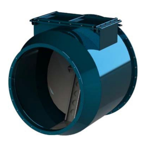
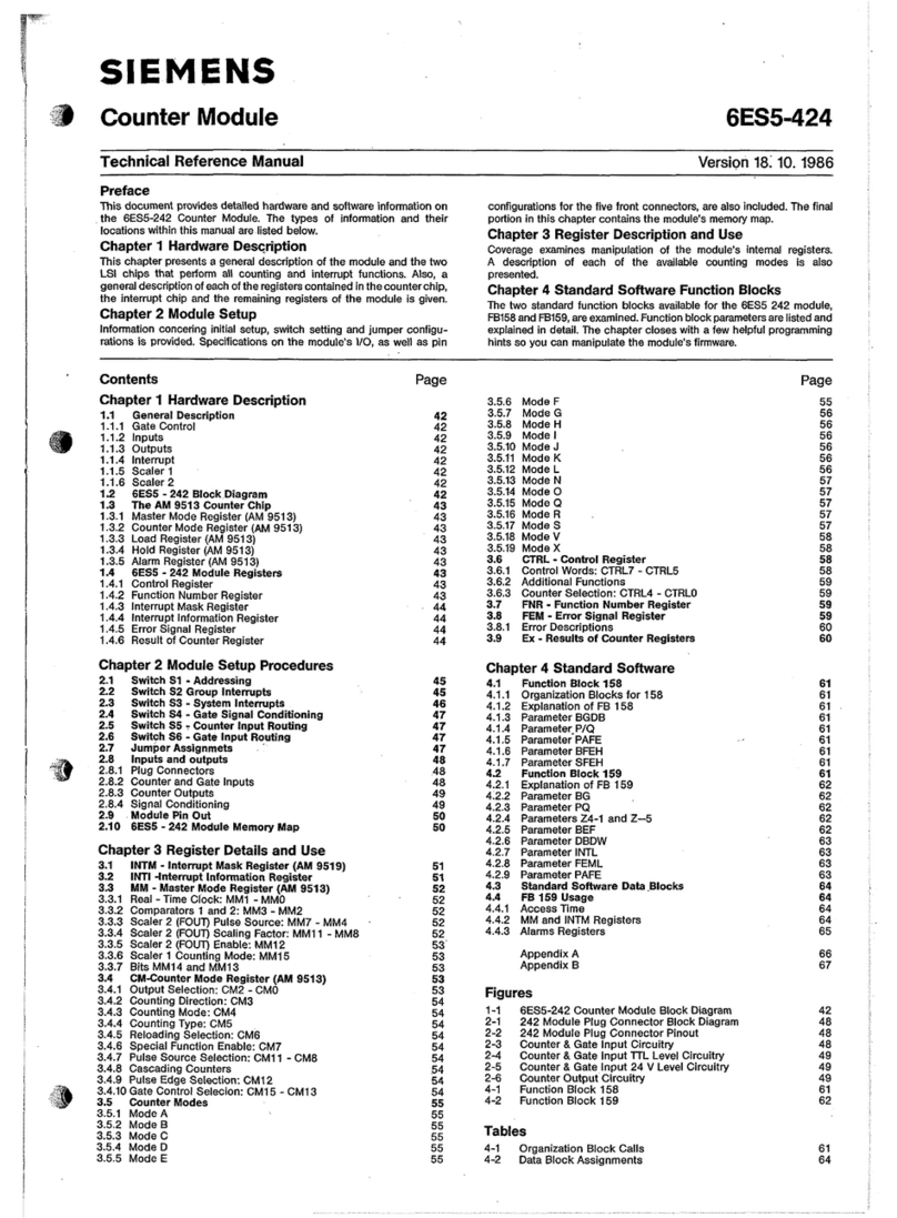
Formula Air BADA-VEX User manual

BADA-VEX
ATEX non-return valves
Maintenance manual (EN)
V1.2-2023

Maintenance manual | BADA-VEX ATEX non-return valves
www.formula-air.com
2
Table of content
1. Introduction ..................................................................................................................................................... 4
2. Preamble......................................................................................................................................................... 4
3. Safety information............................................................................................................................................ 4
4. Standards and certificates............................................................................................................................... 5
4.1. BADA-VEX range is according to following standards :........................................................................... 5
4.2. Manufactured according to quality standards : ....................................................................................... 5
4.3. Conformity of complementary standard :................................................................................................. 5
5. Working features ............................................................................................................................................. 5
5.1. BADA-VEX range: DN 160 to DN800 (DN 6” to DN 32”)....................................................................... 5
5.2. Working airflow: Under-pressure airflow (pull flow) ................................................................................. 5
5.3. BADA-VEX installation features (Tab-1) : ................................................................................................ 6
6. BADA-VEX working ......................................................................................................................................... 6
6.1. Airflow rules : .......................................................................................................................................... 6
6.2. Explosion risk direction : .......................................................................................................................... 7
6.3. BADA-VEX working modes: .................................................................................................................... 8
6.4. Setting of working mode :........................................................................................................................ 9
6.4.1. Floating flap mode : ....................................................................................................................... 9
6.4.2. Flap kept open mode by mechanic system :.................................................................................. 10
6.4.3. Flap position indicator, when it’s opened : ................................................................................... 12
6.4.4. Flap position in idle position (only for floating flap mode) :............................................................ 12
6.4.5. Flap indicator in waiting position :................................................................................................ 13
6.4.6. Flap locked in closed position :..................................................................................................... 13
6.4.7. Indicator position with flap locked closed :................................................................................... 14
7. Installing the BADA-VEX................................................................................................................................ 14
7.1. Rules to install the BADA-VEX : ............................................................................................................. 14
8. Overall dimensions (The list of models is not exhaustive) ................................................................................ 19
8.1. BADA-VEX range in metric « DN » (TAB-4) ............................................................................................ 19
8.2. BADA-VEX range in imperial « DN » (TAB-5) ......................................................................................... 20
9. Flap locking sensor (in closed position)........................................................................................................... 20
9.1. Inductive sensor Ø12 non-ATEX zone (DN≤350 - DN≤14") : ................................................................. 21
9.2. Optional : inductive sensor Ø12 for ATEX zone - II 2 D (DN≤350 - DN≤14") :............................... 21
9.3. Inductive sensor Ø18 non-ATEX zone (DN≥400 - DN≥16") : ................................................................. 22
9.4. Optional : inductive sensor Ø18 for ATEX zone - II 2 D (DN≥400 - DN≥16"): ................................ 22
10. Dust build-up sensor.................................................................................................................................. 22
10.1. Capacitive sensor Ø12 for ATEX zone - II 1 D:.............................................................................. 24
11. ATEX marking............................................................................................................................................ 25
11.1. Certification features :........................................................................................................................... 25
11.2. Scope of the standards present on product marking :............................................................................ 25
11.3. Marking example : ................................................................................................................................ 25
12. Aeraulic pressure loss ................................................................................................................................ 26

Maintenance manual | BADA-VEX ATEX non-return valves
www.formula-air.com
3
12.1. Pressure loss graphs.............................................................................................................................. 26
12.2. Pressure loss values (in mm H2O /inch Wg) measured at 20 m/s (4000 ft/min) (TAB-8). ........................ 27
13. Maintenance operations and periodic inspections..................................................................................... 28
13.1. Standard requirements :........................................................................................................................ 28
13.2. Periodic inspection operations : ............................................................................................................ 28
13.3. Check all following points (TAB-9):........................................................................................................ 29
13.4. Procedure in case of an explosion :....................................................................................................... 29
14. Dismantling and recycling ......................................................................................................................... 30
15. Maintenance log ....................................................................................................................................... 31
Contacts................................................................................................................................................................. 32

Maintenance manual | BADA-VEX ATEX non-return valves
www.formula-air.com
4
1. Introduction
This manual cannot be reproduced, even partially, without prior written consent by Formula Air Group. Every step of
the ATEX non-return valve range has been deeply analyzed by Formula Air Group in the expected area during the
design, construction, and user manual creation. However, it is understood that nothing can replace the experience,
training and good sense of those professionals who work with the device.
Ignoring the cautions and warning from the present user manual, using improperly parts or the whole device supplied,
using unauthorized spare parts, manipulating the device by non-qualified personnel, violation of any safety norm
regarding design, construction and use expected by the supplier, exempt Formula Air Group from all responsibility in
case of damages to people or properties.
Formula Air Group does not take any responsibility for the non-observance of the user about the preventive safety
measures presented in this user manual.
Failure to comply with the requirements of the user manual or incorrect use of the ATEX non-return valve during
operation can lead to the damage of the ATEX non-return valve and improper functioning of the ATEX non-return
valve itself. This will result in termination of the warranty on the item and will release the manufacturer from any liability.
Certification
The BADA-VEX non-return valve range is conform to ATEX norms EN16447 & EN15089.
Warranty : Refer to the general sales condition in regards to the device’s warranty.
Attention !
All drawings and references contained within this user manual are non-contractual and are subject to change without
prior notice at the discretion of the Formula Air Group and its partners.
Copyright © Formula Air.
2. Preamble
Before proceeding to the installation of the valve, please read carefully the following instructions.
Warning :
All instructions contained within this manual have to be fully understood and absolutely followed in
order to guarantee the proper functioning of the BADA-VEX ATEX non-return valve. If you have any
questions, especially in specific applications, please contact FORMULA AIR.
3. Safety information
The BADA-VEX is a protection device for dust ATEX zone (EX II D). The facility manager has to implement the European
regulation 1999/92CE. To be sure that this device is correctly used, the authorized workers have to be trained on the
warning signs and safety rules to ensure the safety of people and facilities.
Non-return valve safety rules according to the standards EN 16447. The explosion isolation non-return valves
have not to be used to protect installations with the following substances, nor a mixture containing some of
these substances:
a) Gas, steams or hybrid mixing
b) Unstable chemical substances
c) Explosive substances
d) Pyrotechnic substances
It is mandatory to respect the pipe length between the protected vessel and the BADA-VEX according to
minimum (Lmin) and maximum length (Lmax) to assure the BADA-VEX isolation in case of explosion.
The vessel(s) connected to the BADA-VEX must be protected :
− Either by an explosion venting device (vent panel, flameless)
− Or a suppression system
BADA-VEX is designed to isolate a vessel with a pressure resistance of ≤0.5 bar (Pred). In case the vessel
has a higher resistance, the explosion discharge device has to be defined with maximum reduced pressure in
it of (Pred) ≤0.5 bar. The pipes before and after the BADA-VEX need to resist to 2 bar (like the BADA-VEX).

Maintenance manual | BADA-VEX ATEX non-return valves
www.formula-air.com
5
Don’t use the BADA-VEX to support the pipes upstream or/and downstream. It should not be subjected to
strong vibration to keep its isolation integrity in case of explosion.
Assure the electrical continuity of the installation (earthing) by connecting the BADA-VEX with earth wires to
both pipes.
4. Standards and certificates
4.1. BADA-VEX range is according to following standards :
• 2014/34/UE ATEX regulation
• EN 16447 : 2014 Explosion isolation flap valves
• EN 15089 : 2009 Explosion isolation systems
• EN 1127-1 :2019 Explosion prevention and protection - Part 1
• EN 14460 : 2018 Explosion resistant equipment
4.2. Manufactured according to quality standards :
• 0080 N° of notified body in charge of checking (INERIS)
• INERIS 23ATEX0012X N° of EU type examination certificate
4.3. Conformity of complementary standard :
• NFPA 69 : 2019 Explosion Prevention Systems
5. Working features
BADA-VEX is an ATEX protective device equipped with a mobile flap which will close under explosion overpressure
and will lock in closed position to avoid the flame to propagate through the ducting to another part of the facility
(suction inlet, filter…).
BADA-VEX is certified for PUSH and PULL flow installations.
BADA-VEX seal the pipe to stop explosion from spreading, either if the explosion come from in opposite direction of
the air + dust flow (example: see picture 1, page 5: “position ”) or if the explosion come from the direction of the
clean airflow (example: see picture 2, page 5: “position ”). In this second case, you need to use the non-return valve
with the flap locked in open position.
Working limits of the BADA-VEX range are defined to ensure the safety of workers, equipment and the
installation. Upholding these limits are the responsibility of the Management exploiting the premises.
5.1. BADA-VEX range: DN 160 to DN800 (DN 6” to DN 32”)
5.2. Working airflow: Under-pressure airflow (pull flow)
Over-pressure airflow (push flow)
• Bends are allowed upstream and downstream of the BADA-VEX, no quantity limit or position restrictions,
• The BADA-VEX can be installed in vertical position (Pictures 15 + 16)
Kst,max ≤250 bar.m/s
Pred,max * ≤ 0.5 bar Airflow speed Clean air side : ≤ 30 m/s
Loaded air side : ≤ 45 m/s
Kst,min No limit BADA-VEX
resistance 2.0 bar Placement Air & dust ducting
Clean air ducting
Pmax 10 bars ATEX marking II D Airflow range Under-pressure : Pull flow
Over-pressure : Push flow
MIE ≥ 10 mJ ATEX inside Zone 20 (II 1 D) Over-pressure
limit 500 mbar max
MIT ≥ 400°C Dust type** All dust types Under-pressure
limit - 800 mbar max
MESG 1.7 mm Dust
concentration No limit Qty.of bends No limit
* Vessel (potential explosion source)
** Organic dust, synthetic dust or metal dust according to the limits defined above.
A
D

Maintenance manual | BADA-VEX ATEX non-return valves
www.formula-air.com
6
Working temperature
Standard : flap gasket in EPDM -30°C to +70°C / -22°F to 158°F
Option : flap gasket in SILICONE -10°C to +180°C*** / 14°F to 356°F***
***Caution: With standard sensor, the working temperature is limited to 70°C / 158°F. Option is available up to
150°C/302°F only for locking sensor.
5.3. BADA-VEX installation features (Tab-1) :
DN Vmin Lmin Lmin +2m Lmax
Ø160 (6") 0,70 m³ 4,0 m 6,0 m 17 m
Ø160 (6") 1,35 m³3,0 m 5,0 m 17 m
Ø180 (7") 0,70 m³4,0 m 6,0 m 17 m
Ø180 (7") 1,35 m³3,0 m 5,0 m 17 m
Ø200 (8") 1,35 m³4,6 m 6,6 m 17 m
Ø250 (10") 1,35 m³4,0 m 6,0 m 17 m
Ø300 (12") 2,90 m³4,6 m 6,6 m 17 m
Ø350 (14") 2,90 m³4,2 m 6,2 m 17 m
Ø400 (16") 4,50 m³5,2 m 7,2 m 17 m
Ø450 (18") 4,50 m³4,7 m 6,7 m 17 m
Ø500 (20") 6,05 m³5,8 m 7,8 m 17 m
Ø550 (22") 6,05 m³5,5 m 7,5 m 17 m
Ø600 (24") 7,65 m³7,2 m 9,2 m 17 m
Ø650 (26") 7,65 m³6,7 m 8,7 m 17 m
Ø700 (28") 7,65 m³6,4 m 8,4 m 17 m
Ø750 (30") 10,00 m³7,3 m 9,3 m 17 m
Ø800 (32") 10,00 m³6,9 m 8,9 m 17 m
Vmin : Min vessel volume being protected by BADA-VEX isolation valve.
Lmax : Max installation distance between the vessel and the BADA-VEX.
Lmin : Min installation distance between the vessel and BADA-VEX, for floating flap with straight horizontal pipe,
no bends.
Lmin + 2 m : Min installation distance between the vessel and BADA-VEX in at least one of following cases :
− Flap locked open by its spring system,
− Pipe with bend between isolated vessel and BADA-VEX, flap in horizontal position ±10° (see picture
18),
− Pipe with bend between isolated vessel and BADA-VEX, flap in vertical position, observe following rules :
Min installing distance = Lmin+2m, if vertical pipe from bend to BADA-VEX > 5 x Øpipe,
Or
Min installing distance = Lmin+2m +5 x Ø, if vertical pipe from bend to BADA-VEX = 5 x Øpipe.
Installation of BADA-VEX in vertical position must be with vertical pipe of min 5 x Øpipe between bend and
BADA-VEX (see picture 16).
6. BADA-VEX working
6.1. Airflow rules :
BADA-VEX is certified to work with under-pressure airflow (Pull flow) or over-pressure airflow (Push flow).
BADA-VEX can be installed in position A and B (picture 1) on the LOADED air side or in position D and E (picture
2) on the CLEAN air side. In position D and E the BADA-VEX needs to be locked open with the mechanical
system.
The working direction of airflow (Push flow or Pull flow) has no influence on the min installation distance.
The working position D and E are advised to inject back the clean air inside the workplace. It’s recommended to
not use the position C (picture 3) and F (picture 4).

Maintenance manual | BADA-VEX ATEX non-return valves
www.formula-air.com
7
6.2. Explosion risk direction :
BADA-VEX installation must observe the direction of the "EXPLOSION RISK" arrow. In fact, this arrow
indicates the direction of explosion flame which has to be stopped by the BADA-VEX, not the normal
working airflow.
Loaded airflow
Clean airflow
Angular position
indicator of flap
Installation direction
Standard working
airflow
DE
A
B

Maintenance manual | BADA-VEX ATEX non-return valves
www.formula-air.com
8
6.3. BADA-VEX working modes:
BADA-VEX can function following 2 modes: either with floating flap (picture 5) or flap kept open (picture 6).
According to the chosen mode, you have to observe the installation distance Lmin and Lmax. These values have
to be checked following the chosen mode as well as the volume of vessel with potential explosion risk (see Tab-
1 page 4).
Floating flap mode, the flap is opened by the working airflow. When the fan stops, the flap closes itself by its
weight without locking (wait to open).
Kept open flap mode, flap is kept open by strip spring system in max opened position. In this mode, the BADA-
VEX can be installed on the clean air side. The kept open flap position can support air speeds up to 30 m/s (6000
ft/min) without closing. It also can be installed in loaded air to reduce the pressure drop especially with low
airflow speeds.
We advise using BADA-VEX in floating flap mode when it’s installed in loaded airflows (working flow in opposition
direction of explosion). However, BADA-VEX has to be used in keep opened flap mode when it’s installed on the
clean air side (explosion flame in same direction than working flow) according to direction of explosion risk.
Only the overpressure of an explosion is capable of activating the locking system of the valve.
Clean airflow
Picture 5
Picture 6
Mode with floating flap
without spring system(s)
Mode with flap kept open
Arm blocked by spring
system
Loaded airflow
Loaded airflow
A
B
D
E
A
B

Maintenance manual | BADA-VEX ATEX non-return valves
www.formula-air.com
9
6.4. Setting of working mode :
The BADA-VEX is delivered from the factory in the ‘Locked Open’ position. If you want to use the BADA-
VEX with a ‘Floating Flap’ remove the external protection cover and take the following measures :
Be sure that the installation is switched off before operating on the BADA-VEX and remove the protect
cover.
6.4.1. Floating flap mode :
To set up the BADA-VEX in mode : floating flap, you have to take off the spring strip(s) to allow the flap to move
freely (picture 7 and 7b).
Caution : the outside arm is part of the moving parts. The weight of this subassembly is high for the BADA-
VEX ≥DN 400 (16"). Be especially careful when handling it, don’t put your hand either in the moving zone nor
in the gasket zone of the flap inside the body.
The arm of the flap is
locked in closed position
by the mechanical
locking system
Cover
D
Picture 7
BADA-VEX floating flap mode DN160 (6")
to DN450 (18")
Remove the following parts :
A) Spring strip
B) Pin
C) Bolt and screw
D) Pin lock
E) Locked open leaf spring
A B
C
Damper arm
E

Maintenance manual | BADA-VEX ATEX non-return valves
www.formula-air.com
10
6.4.2. Flap kept open mode by mechanic system :
The BADA-VEX is delivered from factory in mode: Flap kept open by mechanic locked system. If you have to
change the working mode into floating flap position, to set back the BADA-VEX in flap « locked open position”
mode or to place again the flap in kept open position, you have to take off the protection cover and undertake
the following operations :
1. To set back on mode: flap kept open by mechanic system, you have to put in place the spring strip(s) ref. A
on the bracket(s) ref. E operate in opposite way as described in the pictures 7 or 7b. Then tighten the bolt
to 5 Nm and loosen by a ¼ turn.
2. To place again the flap in kept open position by mechanic system (picture 8 and 8b). Step 1, you have to
turn the spring strip(s) ref. A to outside position in order to raise the arm against the top stop part ref. F.
Step 2, you have to turn back the spring strip(s) under the outside arm and slowly release the arm. Now, you
have to lock the spring strip(s) in position with the pin ref. B and pin lock ref. D.
It’s forbidden to use the BADA-VEX without protection cover.
You have to put the cover back in place with fixing screws after each operation.
Picture 7b
BADA-VEX floating flap mode DN500 (20")
to DN800 (32")
Remove the following parts :
A) 2 spring strips
B) 2 pins
C) 2 bolts and nuts
D) 2 pin locks
E) Locked open leaf springs
Cover
D
C
E
B
Damper arm
A

Maintenance manual | BADA-VEX ATEX non-return valves
www.formula-air.com
11
In function of the BADA-VEX size, 3 models of flap kept open system exist. Number and design of spring strips
are defined in this table (Tab-2):
BADA-VEX
range
Ø160 to Ø350
Ø6" to Ø14"
Ø400 to Ø450
Ø16" to Ø18"
Ø500 to Ø800
Ø20" to Ø32"
Version rep. A Flexible Rigid Rigid
Qty rep. A x1 x1 x2
Drawing
Turn the spring strip(s)
towards the outside ref.
A
Damper arm F A
Picture 8
BADA-VEX flap kept open by mechanic system
1er step: raise the arm against the top stop part
Example of BADA-VEX DN≤500 (20") with double spring strips.
Operation is the same for all other sizes, only difference about spring strip number.
D
Turn back the spring
strip(s) ref. A under the
arm
B
D
B
Picture 8b
2nd step:
lock the blocking system of the damper arm (and the flap)
AAA
A

Maintenance manual | BADA-VEX ATEX non-return valves
www.formula-air.com
12
6.4.3. Flap position indicator, when it’s opened :
Totally open position is visible from outside via angular indicator ref. G (picture 9) independently of the running
mode: flap kept open position from mechanic system or floating flap. When the flap is open, the indicator ref. G
is on the top of the green part.
6.4.4. Flap position in idle position (only for floating flap mode) :
In floating flap mode the BADA-VEX flap is simply opened by airflow generated by the fan. When the fan is
stopped, the flap drops down and the outside arm rests against the locking spring strip ref. H but unlocked by
bottom spring(s) ref. I (picture 10).
Picture 9
G
Green zone is the
angular sector where
the flap can move.
Flap outside arm in
idle position
H
Picture 10
I

Maintenance manual | BADA-VEX ATEX non-return valves
www.formula-air.com
13
6.4.5. Flap indicator in waiting position :
Flap position in waiting is visible from outside by the indicator ref. G placed in limit of green and red zones.
(Picture 11).
6.4.6. Flap locked in closed position :
The flap can be closed by explosion overpressure or by air flow > 35 m/s in case of BADA-VEX installed on clean
air pipe, position (picture 2). In this case, at the end of the fall, the outside arm pushes the spring(s) ref. I until
the stop part ref. J, so the locked spring strip ref. H comes and lock the outside arm of BADA-VEX ref. K (picture
12).
To unlock the flap, you have to press on the spring ref. I with the outside arm. So, you can push down on the
locked spring strip ref. H in order to release the moving part.
D
In idle position, the flap is
placed at the beginning of
green zone
Picture 11
Picture 12
KH
Outside arm in
locked position
J
I

Maintenance manual | BADA-VEX ATEX non-return valves
www.formula-air.com
14
6.4.7. Indicator position with flap locked closed :
Flap position when it’s closed locked (flame is stopped) is visible from outside by the indicator ref. G placed in
the red zone (picture 13).
7. Installing the BADA-VEX
Verification required before starting the installation :
The installer has to check before starting the installation that the delivered material hasn’t suffered any distortion.
BADA-VEX installation must be realized by qualified staff, especially regarding safety rules for workers when they can
be in ATEX risk zone following European regulation n°1999/92/CE.
Upstream and downstream ducting must match the BADA-VEX pressure resistance (2 Bar).
7.1. Rules to install the BADA-VEX :
1. Always use lifting eyes ref. L when handling the BADA-VEX (picture 19).
2. Respect the installation distances Lmin, Lmax and also volumes Vmin according to the BADA-VEX size
(pictures 16, 17, 18 and see TAB-1).
3. Attach the BADA-VEX on a support bracket to avoid that the pipes support the device’s weight.
4. To put back the access door ref. P, you must tighten the M10 bolts with torque 20 Nm to avoid leakage
(Picture 19).
5. Place gaskets between the BADA-VEX and the pipe flanges on either side.
6. Respect the tightening torque according to the bolt size of fixing flange (TAB-3).
Screw class ≥ 6.8 Tightening torque
M6 5 Nm
M8 10 Nm
M10 20 Nm
7. Select the BADA-VEX working mode (Floating OR ‘Locked Open’ before installation).
NOTE : BADA-VEX is delivered with the flap in the ‘Locked OPEN’ position.
8. Respect the installation tolerances for HORIZONTAL and VERTICAL positioning (picture 14).
Picture 13 G
In closed locked position, the
flap is placed in the red zone

Maintenance manual | BADA-VEX ATEX non-return valves
www.formula-air.com
15
9. Allowed Orientation of BADA-VEX for horizontal and vertical installations (picture 15).
• The positions A and B according to BADA-VEX installations in horizontal position ±10°.
• The positions C, D, E, F, G and H are according if the BADA-VEX is installed in angled or vertical
positions (greater than ±10°).
Picture 14 Horizontal position Vertical position
A B
E
D
C
H
G
F
Figure 15
→
Position Ato E & Bto C
2 possibilities to work:
- flap in floating position
so, it’s open by airflow.
- flap is kept open by
mechanic system, so it’s
always open.
→
Position Cto D & E to D
Always work with flap
kept open by gravity.
→
Position Ato G & Bto G
Always need to work with
flap kept open by
mechanic system, so it’s
always open (if not
pressure drop is too high).

Maintenance manual | BADA-VEX ATEX non-return valves
www.formula-air.com
16
10. Allowed installation distances from isolated vessel to BADA-VEX :
• Multiple bends are permitted (no quantity limit) in any position, upstream or downstream of the BADA-
VEX. The system is functional with bend on the pipe in upstream or downstream of BADA-VEX. Lmin and
Lmax installation distances must be observed (see TAB1).
• Lmax is 17 m, it includes all pipe elements (especially the bends) and it’s measured on the center of the
ducting.
Lmin : Min distance in floating flap mode on straight horizontal pipe (±10°), without bend (picture 17, see
TAB 1).
Lmin+2m : Min distance between isolated vessel and BADA-VEX in at least one of following cases :
− Flap in Locked Open mode (picture 18, see TAB 1).
− Pipe with bend between isolated vessel and BADA-VEX, flap in horizontal position ±10° (see
picture 18).
Pipe with elbow between isolated vessel and BADA-VEX, flap in vertical position (over 10°), observe
following rules (pictures 16, TAB 1) :
* Min installing distance = Lmin+2m, if vertical pipe from bend to BADA-VEX > 5 x Ø pipe,
Or
* Min installing distance = Lmin + 2m + 5 x Ø, if vertical pipe from bend to BADA-VEX = 5 x Ø pipe,
* Installation of BADA-VEX in vertical position must be done with vertical pipe of min 5 x Ø pipe
between bend and BADA-VEX.
11. Reminder of installation conditions of BADA-VEX in horizontal position :
Lmin : In floating flap working, on straight horizontal pipe, without bend (picture 17, see TAB 1).
Lmin + 2m : Min distance between isolated vessel and BADA-VEX in at least one of following cases :
- Flap kept open by its spring system (pictures 17, 18, see TAB 1).
- Pipe with bend between isolated vessel and BADA-VEX, flap in horizontal position ±10°
(see picture 18).
X
Picture 16
BADA-VEX in vertical position
3
1
2
Volume
Volume
Volume
<5 xØ pipe
=5 xØ pipe
>5 x Ø pipe (pipe =5xØ includes in Lmin+2m)
Lmin+2m : Min distance from vessel to BADA-VEX
5 x Ø pipe : Min vertical distance before the BADA-VEX
Complementary distance longer than Lmin+ 2m
1
2
3

Maintenance manual | BADA-VEX ATEX non-return valves
www.formula-air.com
17
Top view
Lmin
Lmin + 2m
Side view
Volume Volume
BADA-VEX in horizontal position, straight ducting
BADA-VEX horizontal position,
Flap help open = Lmin + 2m
BADA-VEX horizontal position,
Flotting flap = Lmin
Volume Volume
Side view
Top view
1
2
3
4
B
5
6
1
2
3
4
B
5
6
Vertical ducting
BADA-VEX in horizontal position,
Flap floating or held open,
No limit on bends,
No position restrictions :
.Bends close to BADA-VEX possible,
.Bends between vessel and BADA-VEX,
.Bends after the BADA-VEX.
BADA-VEX in horizontal position, ducting with bends
= Lmin + 2m : min distance from vessel to BADA-VEX (on center),
The safety distance Lmin + 2m must be measured on the center of ducting.
Picture 17
Picture 18

Maintenance manual | BADA-VEX ATEX non-return valves
www.formula-air.com
18
12. The inspection door is fixed during manufactory, after each maintenance operation, be sure to tighten all M10
bolts @ 20 Nm.
: Lifting eyes (x3)
13. Connect both earthing straps ref. M from the BADA-VEX to the pipes on either side, upstream and
downstream (Picture 20). Before starting to use the BADA-VEX, check electric continuity and that the earthing
connection is efficient.
Picture 19
P
O
O
O
20 N.m -16mm
Option :
Inspection window
Picture 20
M
M
Insert gaskets between the
flanges

Maintenance manual | BADA-VEX ATEX non-return valves
www.formula-air.com
19
8. Overall dimensions (The list of models is not exhaustive)
The BADA-VEX is conceived on seven main body bases. The main bodies are indicated with an “x” in the tables TAB-
4 and TAB-5, they are used for one or two other connected pipe diameter sizes.
The possible pipe diameter sizes are indicated in measure unit : metric (TAB-4) or imperial TAB-5).
The BADA-VEX model is indicated according to the pipe size, example DN200.
8.1. BADA-VEX range in metric « DN » (TAB-4)
Ø BADA-VEX Overall dimensions Flange Duct Mounting support
Ducting
DN Body
LHWXØ ext. Ø axis
mm
qty. ø holes
mm
AHt
axis EFGØ h holes Weight
mm mm mm mm mm mm mm mm mm mm mm Kg
160 x640
386 400 216
215 195 8 10 591 126 282
110 90 12
21
180 612 235 215 8 10 531 136 254 20
200 857 466 490 261 255 235 12 10 857 138 325
160 140 12 35
250 x717 305 285 12 10 671 163 253 33
300 966 575 590 311 355 336 12 10 966 197 373
160 160 12 44
350 x817 415 389 12 12 776 222 302 50
400 1088 705 740 385 465 439 16 12 1089 249 431
180 260 12 81
450 x945 515 489 16 12 893 274 359 77
500 1197 815 840 434 565 540 16 12 1 199 309 441
200 300 12 106
550 x1045 615 590 16 12 996 334 369 104
600 1549
1038 992 508
665 640 16 12 1549 366 588
200 400 12
150
650 1363 715 690 24 12 1364 391 517 150
700 x1207 785 750 24 12 1155 416 446 150
750
1751 1213 1200 602 835 800 24 12 1752 443 514
400 500 12 285
800 x1563 885 850 24 12 1564 468 442 285

Maintenance manual | BADA-VEX ATEX non-return valves
www.formula-air.com
20
8.2. BADA-VEX range in imperial « DN » (TAB-5)
Ø BADA-VEX Overall dimensions Flange Duct Mounting support
Ducting
DN Body
LHWXØ ext. Ø axis
mm
inch
qty. ø holes
mm inch
AHt
axis EFGØ h holes Weight
mm mm mm mm mm mm mm mm mm mm mm Kg
6" x649
386 400 216
209 185,7 7-
5/16 6 7,1 9/32 628 120 291
110
90 12 21
7" 616 238 215,9 8-1/2 6 9,5 3/8 559 133 258 20
8" 857
466 490 261
263 242,9 9-
9/16 6 9,5 3/8 857 138 325
160
140 12
35
10" x717 327 300 11-
13/16 6 11,1 7/16 670 163 253 33
12" 966 575 590 311
384 355,6 14 8 11,1 7/16 965 197 373
160
160 12 50
14" x817 435 406,4 16 8 11,1 7/16 776 222 302 50
16" 1089 705 740 385
486 457,2 18 8 11,1 7/16 1089 249 431
180
260 12 81
18" x945 536 508 20 8 11,1 7/16 893 274 359 77
20" 1199
815 840 434
587 552,5 21-
3/4 12 11,1 7/16 1199 309 441
200
300 12
110
22" x1039 638 603,3 23-
3/4 12 11,1 7/16 981 336 364 110
24" 1541
1038 992 508
689 657,2 25-
7/8 12 11,1 7/16 1538 368 582
200
400 12
178
26" 1353 766 720,7 28-
3/8 16 11,1 7/16 1353 393 512 170
28" x1200 816 771,5 30-
3/8 16 11,1 7/16 1138 419 438 170
30" 1739
1213 1200 602
867 822,3 32-
3/8 16 11,1 7/16 1739 444 508
400
500 12
285
32" x1548 918 873,1 34-
3/8 16 11,1 7/16 1545 470 435 285
9. Flap locking sensor (in closed position)
The BADA-VEX is equipped with an inductive sensor (external) which detects when the flap is locked in closed position
(picture 21). It sends a signal to stop the installation when the sensor detects the target screw (ref. Q) in closed position
(explosion is isolated).
The BADA-VEX is equipped in standard execution with a non-ATEX detector version. Optionally, ATEX sensors are
available for ATEX II2 D (zone 21).
Sensors have different sizes according to BADA-VEX size :
− Inductive sensor Ø12 for BADA-VEX DN≤350 (DN≤14")
− Inductive sensor Ø18 For BADA-VEX DN≥400 (DN≥16")
We advise combining the position sensor to a sound alarm, light alarm or process PLC to have information regarding
the locking closed position of flap following an explosion accident or unusual running.
The sensor works in positive safety running, (NC switch) when the flap is not locked in closed position.
The sensor installations is set in the factory. In case of its replacement, you have to simulate the locked in
closed position of outside arm in order to set the target screw (ref. Q) in front of the sensor in detection
condition. You will have to adjust the length of the target screw (ref. Q) until the sensor status changes
(switches off), then tighten the counter-nut to lock the setting.
Table of contents
Other Formula Air Control Unit manuals
