Forster TAP0-EZ1-38-M User manual
Instruction Manual
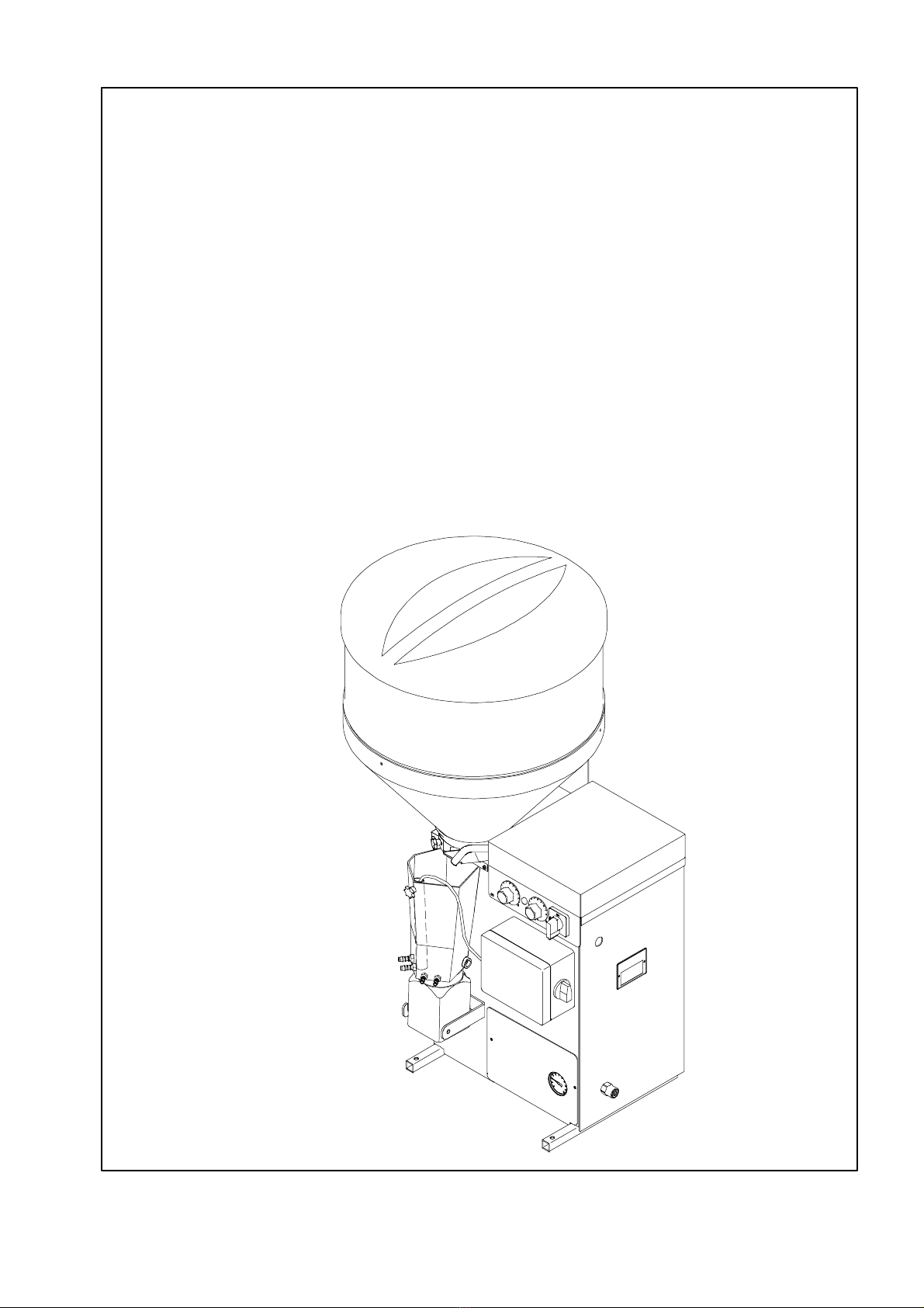
Automatic Lamb Feeder
TAP0--EZ1--38--M
TAP0--EZ1--32--M
TAP0--EZ1--28--M
TAP0 -- EZ1 -- 27
December 2002


3
Table of contents
1 Introduction 4...........................................................
1.1 Safety Instructions 4...............................................................
1.2 Danger Signs on the Automatic Feeder 4.............................................
1.3 Information Signs on the Automatic Feeder 5..........................................
1.4 Components of the Automatic Feeder 6..............................................
2 Specifications of the Automatic Feeder 7..................................
3 Locating the Automatic Feeder 8.........................................
3.1 Local Electrical Connection 8........................................................
3.2 Installing the Automatic Feeder 8....................................................
3.3 Water Supply 9....................................................................
3.4 Mounting the Feeding Station 10......................................................
3.5 Mounting the Top Section of the Milk Powder Hopper 11.................................
4 Starting Up the Automatic Feeder 12.......................................
4.1 Filling the Boiler with Water 12........................................................
4.2 Filling the Milk Powder Hopper 12.....................................................
4.3 Setting the Concentration 13.........................................................
4.4 Setting the Temperature 13..........................................................
4.5 Avoiding Measurement Errors 14.....................................................
4.6 Measuring the Temperature 14.......................................................
5 Functionality 15..........................................................
5.1 Program Switch Positions 15.........................................................
6 Care and Maintenance of the Automatic Feeder 16..........................
6.1 After Start--Up 16...................................................................
6.2 Regular Check 17..................................................................
6.3 Shutdown 17.......................................................................
6.3.1 In case of Frost Risk 18........................................................
7 Troubleshooting 19.......................................................
EC DECLARATION OF CONFORMITY A.......................................

4Introduction
1 Introduction
1.1 Safety Instructions
Be sure to read and follow all instructions contained in this manual before connecting and
using the automatic feeder.
:Use the appliance only to feed lambs or kids.
:Servicing and installation of the automatic feeder has to be restricted to qualified and
authorised service personnel.
:Read the instruction manual carefully before installing or operating the machine.
To facilitate customer service on the automatic feeders, store the documentation accom-
panying the appliance near to it.
:The faultless functioning of the automatic feeder requires expert installation, correct
handling, as well as careful care and maintenance.
:Incorrect data inputs may have serious consequences. Therefore, check the correctness of
all data inputs.
:The livestock owner is responsible for a regular and scrupulous control of his animals
and the functioning of the appliance. If, for any reason, the system should break down or
some animals should not make use of it, the livestock owner is responsible for choosing
other feeding methods for those animals.
:The manufacturer accepts no responsibility for damages and their consequences caused
by incorrect installation and operation, improper use, inadequate service and mainte-
nance or false entries.
:You will find further safety instructions in the following chapters.
1.2 Danger Signs on the Automatic Feeder
CAUTION!
This sign warns you of rotating parts starting to work automatically.
This sign is located on potential danger areas such as the milk powder
hopper, the milk powder outlet, the mixer as well as the outlet for pow-
der additives on the additive dispenser.
In order to avoid injuries, before carrying out any kind of operation on
above--listed parts, it is imperative to make the automatic feeder current-
less by turning the main switch to position „0/OFF“ or by pulling the
mains plug.
CAUTION!
This sign warns you of electric shocks.
In order to avoid injuries, before opening the control-- or the power unit,
it is imperative to make the automatic feeder currentless by turning the
main switch to position „0/OFF“ or by pulling the mains plug.

5
Introduction
1.3 Information Signs on the Automatic Feeder
Before connecting the automatic feeder to the mains supply and acti-
vating the heating (see chapter 4 “Starting Up the Automatic Feeder”,
page 12), carefully read the operating instructions.
Any questions about this product? Then, feel free to get
in touch with us. Before calling us, please write down
the information (machine type, machine number) on
the rating plate located at the left of the feeder chassis,
as well as the program version).
Our address:
Förster--Technik GmbH,
Gerwigstr. 25,
D--78234 Engen,
Tel. +49/(0)7733/9406--0,
Fax +49/(0)7733/9406--99
Internet: www.foerster--technik.de
6Components of the Automatic Feeder
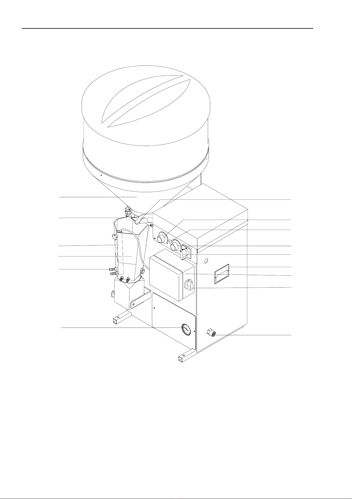
1.4 Components of the Automatic Feeder
1
2
3
4
5
6
7
8
10
11
12
13
14
15
9
1 = Milk powder hopper 9 = Pilot lamp for heating
2 = Dosing slide 10 = Heating thermostat
3 = Pressure tube 11 = Main switch ON/OFF (not for
T A P 0 -- E Z 1 -- 2 7 )
4 = Mixer 12 = Rating plate
5 = Suction hose connection 13 = Power unit
6 = Manometer 14 = Program switch
7 = Milk/Water outlet 15 = Water supply
8 = Thermostat für minimum operating temperature (not for TAP0--EZ1--27)

7
Specifications of the Automatic Feeder
2 Specifications of the Automatic Feeder
Please observe the information on the rating plate located at the left of the chassis!
Electrical connection
T A P 0 -- E Z 1 -- 2 7
230V / L / N / PE, 50 Hz, 16 A
TAP0--EZ1--28--M (only for USA and Canada)
240V / L1, L2 / Grd / 60 Hz, 15 A
T A P 0 -- E Z 1 -- 3 2 -- M
230V / L / N / PE, 50 Hz, 16 A
T A P 0 -- E Z 1 -- 3 8 -- M
230V / 400V / 3 / N / PE, 50 Hz, 16 A
Dimensions of the automatic feeder
Height: 108 cm
Width: 61 cm
Depth: 53 cm
Weight (with basic equipment): approx. 40 kg
Water supply
1/2“ hose with 3/4“ hose coupling.
The local water pressure has to be between 2,5 and 6 bar.
Boiler
Boiler capacity: approx. 6 liters
Milk powder hopper (with top section) -- capacity
approx. 35 kg
Number of feeding stations
Each automatic feeder can provide approx. 20 animals per feeding station with feed.
Specifications are subject to change without prior notice!

8Locating the Automatic Feeder
3 Locating the Automatic Feeder
3.1 Local Electrical Connection
:Refer installation of the local electrical connection to qualified electricians.
:Observe local recommendations and protective measures. To operate the automatic fee-
der, it is demanded to install a fault--current circuit breaker (30 mA) in the main distribu-
tion frame.
:The automatic feeder requires its own power supply: refer to chapter 2, page 7,
„Specifications of the Automatic Feeder“.
:Observe rated voltage and rated frequency. The supply voltage indicated on the rating
plate of the automatic feeder must correspond to the one of the mains.
:In case of overvoltage risk, install an overvoltage limiter in the local main distribution
frame.
For animals’ safety and to prevent electrical interferences, carry out an equipotential bon-
ding of all metal parts such as the water line, the feeding station, the race--way and the auto-
matic feeder. At the rear of the automatic feeder is located the connection screw for the
equipotential bonding which has to be connected to an earth circuit connector or to a local
earth electrode by means of a short coupling.
As it is technically impossible to protect the installation against lightning stroke separately,
it is to the owner to install an adequate lightning protection, such as e.g. a lightning protec-
tion system for the entire building. We recommend to conclude a lightning protection insu-
rance.
3.2 Installing the Automatic Feeder
:The automatic feeder has to be placed in a dry location, if possible, not in the animal
area (e.g. in the fodder storage or similar detached room).
:A fence of planks protects the automatic feeder against dirt and flies.
:In order to ensure a good functioning of the feeding process even in case of frost, you
have to equip the automatic feeder with a protection against frost (accessory). The owner
is responsible for a reliable water supply.
:The suction hoses can be easily guided through a wall.
Equipotential
bonding
Lightning
protection

9
Water Supply
3.3 Water Supply
:Connect the 1/2“ water hose with the 3/4“ screw--type hose coupling to the water
connection located at the right of the automatic feeder.
The water pressure supplied by customer has to be between 2,5 and 6 bar.
Note: To ensure troublefree functioning of the automatic feeder, take care that the water
pressure does not fall below 2,5 bar!
Take care that there is no pressure variation of the water pipe.
In case of water pipes with small cross section it may happen that, in the feeding mode or
when water is taken out of the same pipe simultaneously, the water pressure will drop.
When the water pressure is below 2,5 bar you have to use a header tank.
Install an additional water stop valve.
The pressure reducer is factory--set to 1,5 bar.
Do not alter the setting of the pressure reducer!
In case the notes above should not be observed, there is no guarantee that the automatic
feeder will run trouble- free!
10 Mounting the Feeding Station
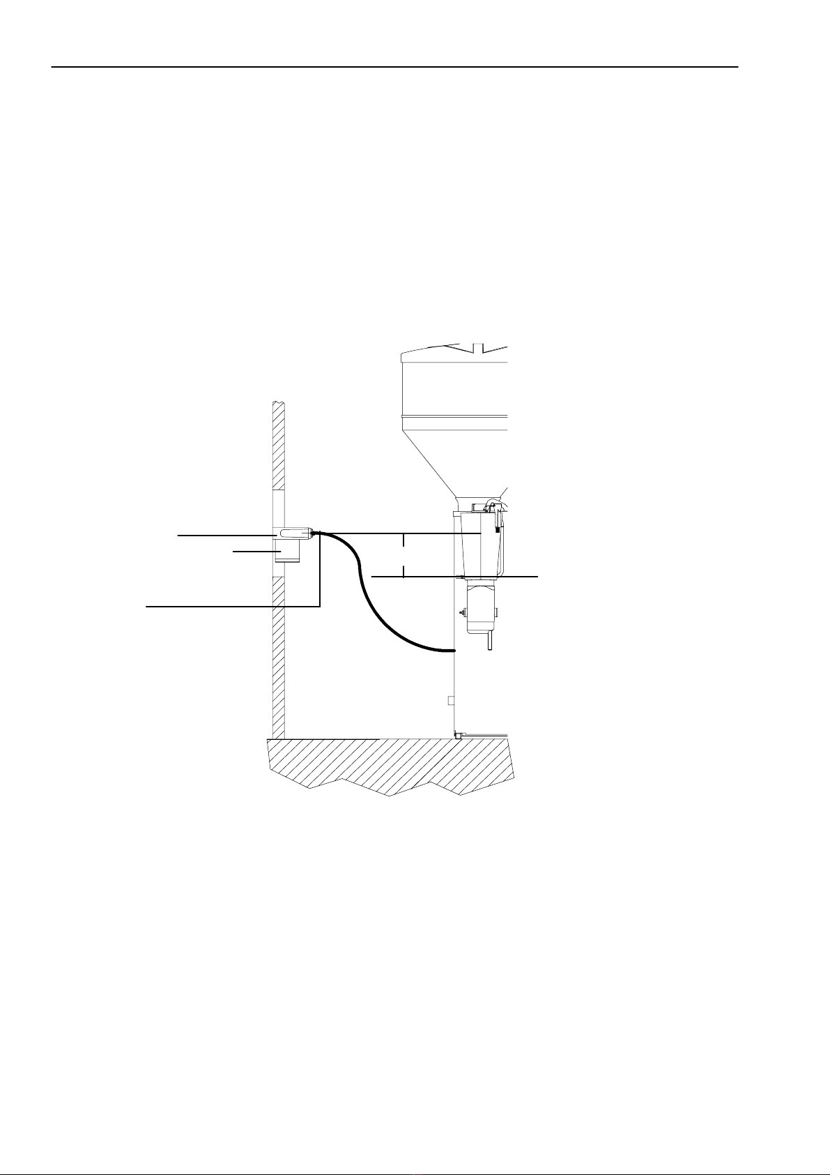
3.4 Mounting the Feeding Station
:Install the feeding station 30 -- 40 cm above the stable ground.
Mount the teat approx. 15 cm above the suction hose connection of the mixer.
:Secure the suction hose in such a way that the mixer jar can easily be tilted in forward
position. The suction hoses should not exceed a length of 2 meters.
:Mount the suction bracket with splash board towards the bottom.
:Make sure that there is no sag in the connecting hose between mixer and feeding pump,
in order to prevent accumulation of water or milk.
Teat at max. 40 cm
height
Suction hose
Suction bracket
The teat should be moun-
ted in the feeding station
approx. 15 cm above the
suction hose connection
of the mixer
15 cm
11
Mounting the Top Section of the Milk Powder Hopper
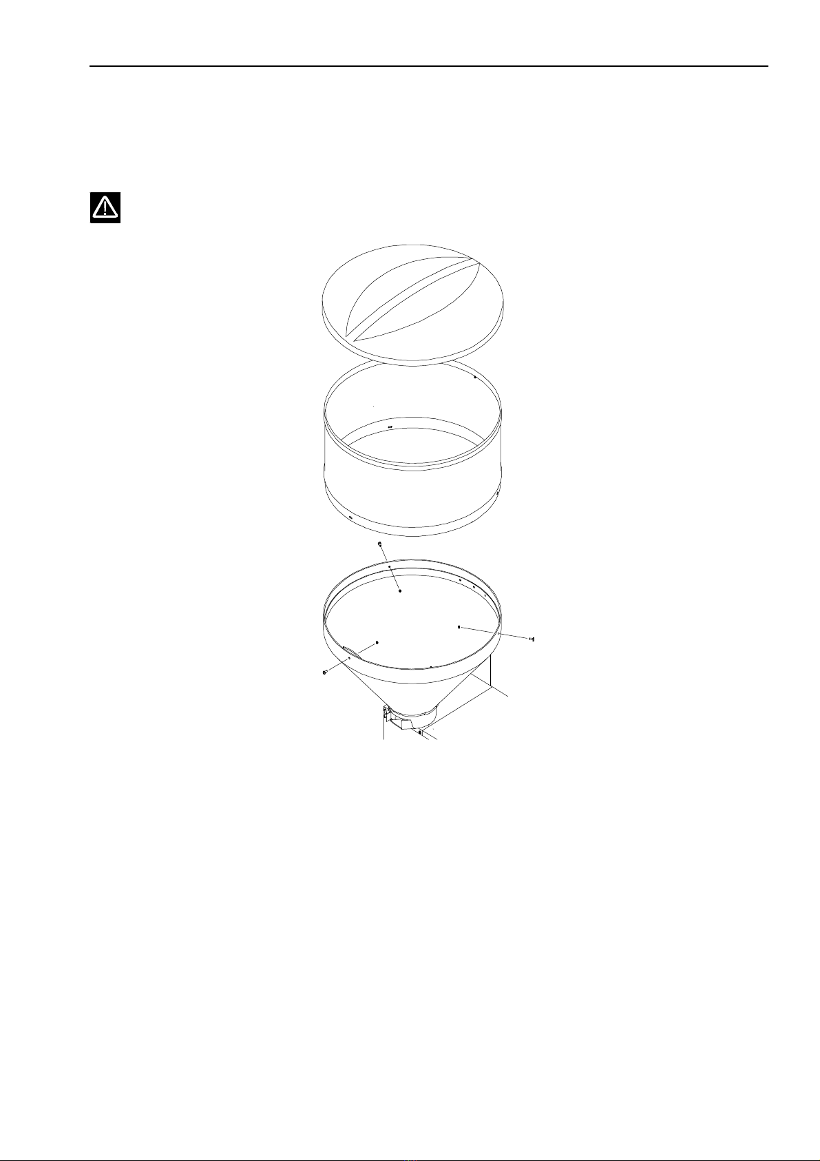
3.5 Mounting the Top Section of the Milk Powder Hopper
:Screw the top section together and place it onto the milk powder hopper.
Only use the original milk powder hopper!
12 Starting Up the Automatic Feeder
4 Starting Up the Automatic Feeder
4.1 Filling the Boiler with Water
Warning: Before switching the heating on, fill up the boiler with water, otherwise the boi-
ler will be damaged. There will be no guarantee for a reliable functioning of the automa-
tic feeder.
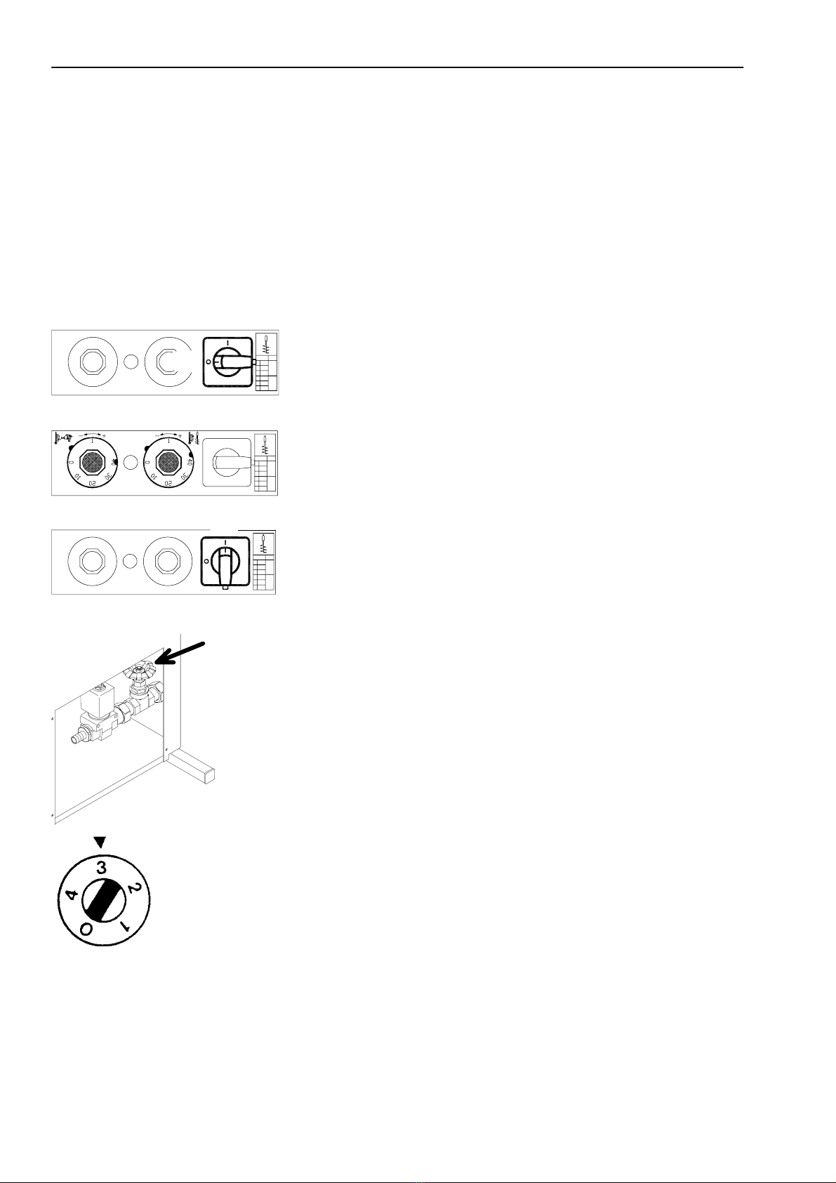
Turn the main switch to 0/OFF.
Turn both thermostats to 0.
Connect the mains plug and turn the main switch to I/ON in order to
switch the automatic feeder on.
Open the water control valve.
Turn the program switch to 3.
4.2 Filling the Milk Powder Hopper
Only fill in milk powder that is suitable for lamb and kid feeding.
OFF
ON
13
Starting Up the Automatic Feeder
Do not put paper or other foreign matter into the powder hopper.
For those models being equipped with a lid protection, check the following:
-- The lid of the powder hopper has to keep the fuse switch pressed.
-- In case the lid should not be mounted properly, the milk powder will not be dispen-
sed.
4.3 Setting the Concentration
The concentration is set by varying the water flow rate.
Take the pressure tube and the water hose out of the mixer.
Hang a cup into the mixer in order to collect the dispensed powder.
Place a measuring cup under the water outlet.
Turn the program switch to 4and collect the dispensed water into a mea-
suring cup.
After having collected 1 liter of water, immediately turn the program
switch to 0.
The milk powder amount that has been dispensed during the same time represents the milk
powder concentration per liter of water.
When the dispensed milk powder amount is too low, close the water con-
trol valve a little bit.
When the dispensed milk powder amount is too high, open the water
control valve a little bit more.
Remount the pressure tube. The lower end must touch the mixer base.
Hang the water hose into the mixer once again.
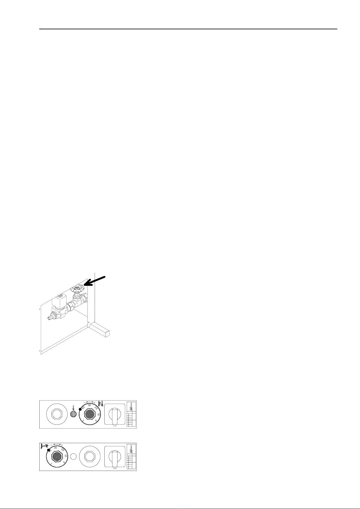
4.4 Setting the Temperature
The boiler has to be filled with water!
Turn the heating thermostat so far clockwise until both red marks will
coincide.
Turn the thermostat for minimum operating temperature so far clockwise
until both green marks will coincide.

14 Starting Up the Automatic Feeder
The thermostat for minimum operating temperature is activated as soon as the water tempe-
rature in the boiler falls below the preset temperature.
The minimum operating temperature has always to be 3EC below the boiler heating tempe-
rature, in order to avoid overlapping in the adjustment range.
The marks are intended to help the operator setting the temperature. Nevertheless, he has to
check the set values on his own authority.
For cold--soluble milk powders, a temperature of approx. 38EC will be sufficient.
For those milk powders containing fats with higher melting point, the outlet temperature has
to be between 42EC and 43EC.
4.5 Avoiding Measurement Errors
The temperature has always to be set very carefully!
Too low temperatures may cause digestive troubles due to undissolved fats.
Too high temperatures may cause inflammation of the mucosa in the abomasum that on its
part may lead to flatulences.
4.6 Measuring the Temperature
Turn the program switch to 1.
Wait until the yellow pilot lamp for heating goes out.
Turn the program switch to 3.
Wait until the water dispense is interrupted by the pressure switch.
Immediately afterwards measure the temperature by means of a precise
thermometer.
Measure the temperature carefully and, if necessary, adjust the thermo-
stats until the desired temperature is reached.
15
Functionality
5 Functionality
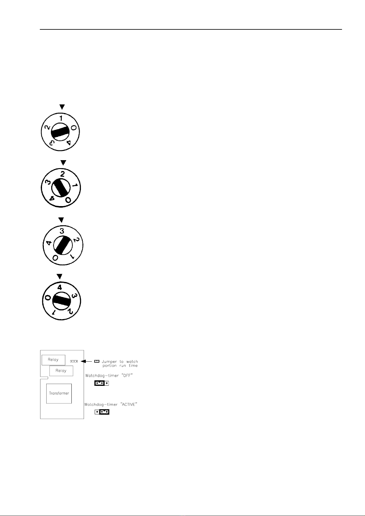
5.1 Program Switch Positions
1 = Option
2 = Mixer ON
3 = Water conveyance
When the pressure tube is located outside the mixer, the water will flow
incessantly.
4 = Automatic mode
The powder, the water and the mixer are activated simultaneously. The
water tank or the pressure reducer are intended to ensure constant flow
velocity. The water control valve is used to set the water flow rate.
The concentration is set by modifying the water flow rate.
The pressure switch connected to the pressure tube switches the water--
and powder conveyance off, as soon as a certain pressure has been re-
ached. After several seconds a relay switches the mixer off. A portion is
prepared as soon as the mixer is empty. In case of water deficiency the
automatic feeder switches off automatically after approx. 40 seconds,
provided that the jumper is in position ON.
16 Care and Maintenance of the Automatic Feeder
6 Care and Maintenance of the Automatic Feeder
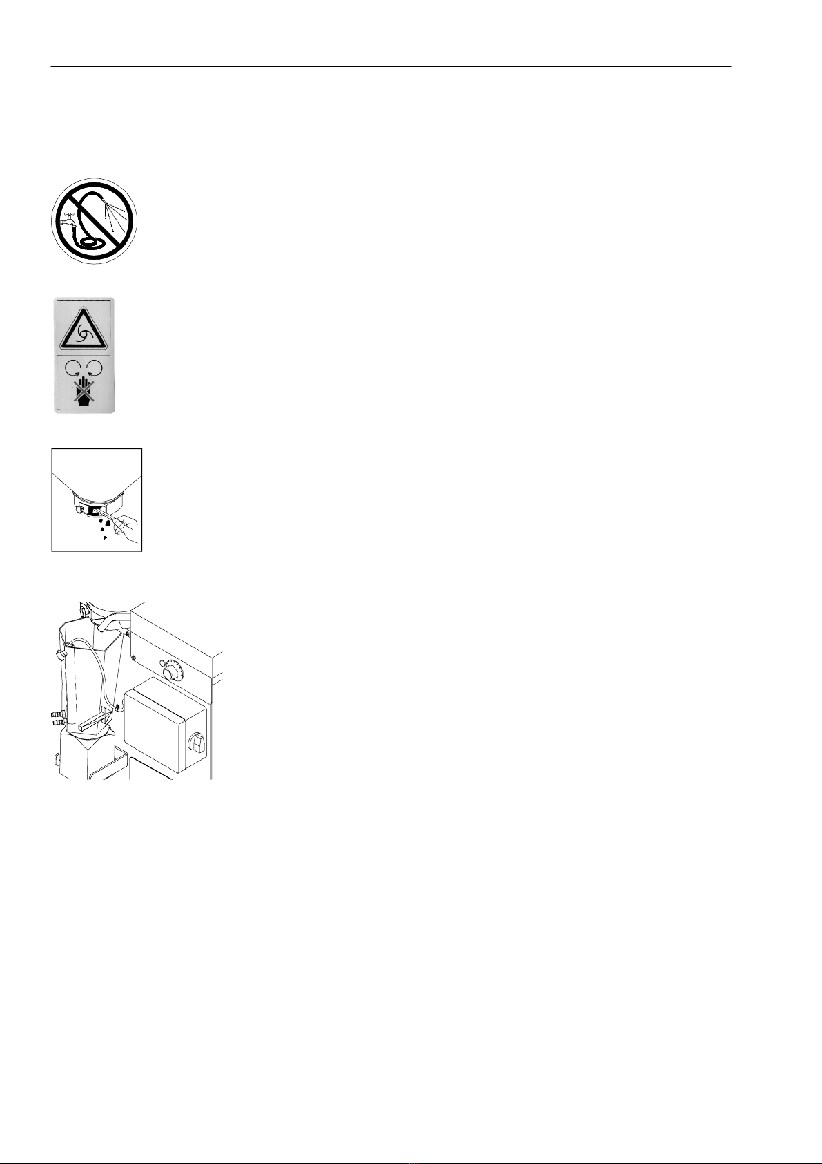
Always keep the automatic calf feeder clean and dry. Never spray it with
water!
CAUTION! In order to avoid injuries, before carryingoutanykindof
operation on the milk powder outlet or on the mixer, it is imperative to
make the automatic feeder currentless by turning the main switch to po-
sition 0/OFF or by pulling the mains plug.
Check the milk powder outlet daily and remove potential incrustations.
Incrustations impair the dosing precision.
In order to avoid injuries, always remove incrustations of the powder
outlet by means of a small piece of wood or similar. Never use your fin-
gers!
Always lay the cable between the pressure tube and the pressure switch
towards the bottom. In case the milk flows into the pressure tube, the
latter will become inoperative.
6.1 After Start--Up
:The day after start--up, carry out the following:
-- Measure the feed temperature
-- Check the concentration of the milk powder.

17
Care and Maintenance of the Automatic Feeder
6.2 Regular Check
Clean the mixer daily.
Remove the suction hoses from the teat and suspend them.
Turn the program switch to 3.
Fill the mixer with water until the pressure switch interrupts water con-
veyance.
Add some detergent also used in dairy farming.
Turn the program switch to 2.
Shortly afterwards, turn the program switch to 0.
Wipe out and empty the mixer resp. drain the cleaning water via the suc-
tion hoses.
Turn the program switch to 3. Rinse with clean water.
Remount the suction hoses on the teat.
Turn the program switch to 4.
Check the concentration of the milk powder after each new milk powder
delivery.
Check the temperature of the milk.
In case of direct water supply, check whether the filter of the pressure
reducer and the solenoid valve are clean. Clean them, if necessary.
6.3 Shutdown
Turn the heating thermostat entirely counter--clockwise. Switch the auto-
matic feeder off by turning the main switch to position 0/OFF and pull
the mains plug.
18 Care and Maintenance of the Automatic Feeder
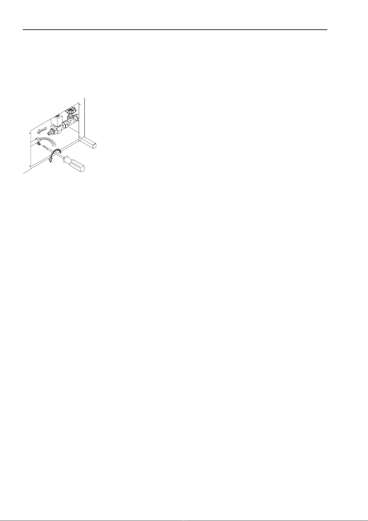
6.3.1 In case of Frost Risk
Drain the whole water from the boiler and the pressure reducer.
Remove the boiler hose and hold the hose towards the bottom to drain
the water.
Remount the boiler hose.
Remove the whole pressure reducer and drain the water.
Remount the pressure reducer.
For reinstallation, proceed as for start--up.

19
Troubleshooting
7 Troubleshooting
We assume that the automatic feeder has been installed according to the information
contained in this instruction manual and that the setting has been carried out cor-
rectly.
The causes are listed according to their frequecy. Therefore, during troubleshooting always
start with the first one.
Fault Cause Countermeasure
1. The automatic feeder does not
t
i
t
h
The lid is defective. Close the lid.
prepare any portion; the green
LED is not illuminated. The minimum operating tempera-
ture has not been attained.
Check the heating and the thermo-
stats.
The line is interrupted. Check the supply lead.
The mains supply fuse (2,5 A) is
defective.
Replace the fuse.
2. The automatic feeder does not
prepare any portion; the green
LED is illuminated.
There is water in the hose between
the pressure tube and the pressure
switch.
Clean and dry the hose.
There is water in the pressure tube. Replace the pressure tube.
3. The feed overflows. The pressure tube is leaky. Check the pressure tube. Seal it, if
necessary.
The hose between the pressure
tube and the pressure switch is lea-
ky.
Check the hose. Replace it, if ne-
cessary.
The pressure tube is damaged. Replace the pressure tube.
The water solenoid valve does not
close.
Replace the water solenoid valve.
4. The powder motor runs continu-
o
u
s
l
y
(
o
n
l
y
f
o
r
a
u
t
o
m
a
t
i
c
f
e
e
d
e
r
s
The water supply is interrupted. Check the water supply.
ous
l
y
(
on
l
y
f
or au
t
oma
t
i
c
f
ee
d
ers
that are not equipped with an elec-
tronic protection against water de-
ficiency).
The water solenoid valve does not
open.
Check the water solenoid valve
and the pressure reducer. Replace
them, if necessary.

20 Index
A
address, Förster--Technik, 5
B
boiler, 7
C
care and maintenance, 16
components of the automatic feeder, 6
connection
suction hose, 10
water, 9
E
electrical connection, 7
local, 8
equipotential bonding, 8
F
fault--current circuit breaker, 8
feeding stations per automatic feeder, 7
frost protection, 8
functionality, 15
I
installing the automatic feeder, 8
L
lightning protection, 8
locating the automatic feeder, local electrical connec-
tion, 8
M
machine type, machine number, 5
main switch, 12
mains plug, connect, 12
maintenance, 16
milk powder hopper, capacity, 7
milk powder outlet, check, 16
mounting
the feeding station, 10
the suction bracket, 10
the top section of the milk powder hopper, 11
O
overvoltage, 8
P
pressure reducer, 9
R
rated frequency, 8
rated voltage, 8
rating plate, machine type, machine number, 5
S
safety instructions, 4
signs
danger signs, 4
information signs, 5
specifications of the automatic feeder, 7
boiler, 7
capacity of the milk powder hopper, 7
dimensions, 7
electrical connection, 7
number of feeding stations, 7
water supply, 7
weight, 7
start--up
automatic feeder, 12
avoid measurement errors, 14
fill the boiler with water, 12
fill the milk powder hopper, 12
measure the temperature, 14
set the concentration, 13
set the temperature, 13
suction hose, 10
T
troubleshooting, 19
W
water pressure, 9
This manual suits for next models
3
Table of contents
Other Forster Farm Equipment manuals


Popular Farm Equipment manuals by other brands

Norwood
Norwood Kwik-Till HSD1600 Operator's manual

Sulky Burel
Sulky Burel X40+ ISOBUS Technician's Operating Manual

Kellfri
Kellfri 35-HKKFE Original operating instructions

AGCO
AGCO HayBoss G2 600A1 installation manual

Raven
Raven RS1 HDU installation manual

Ferrari Costruzioni Meccaniche
Ferrari Costruzioni Meccaniche REMOWEED Operating and service manual


