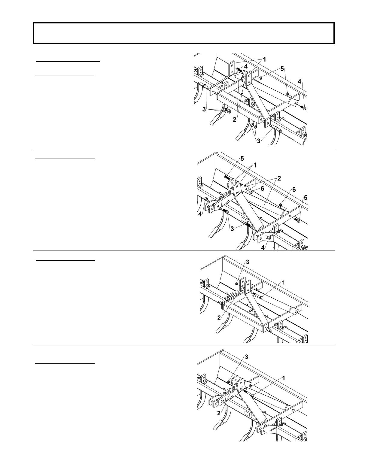
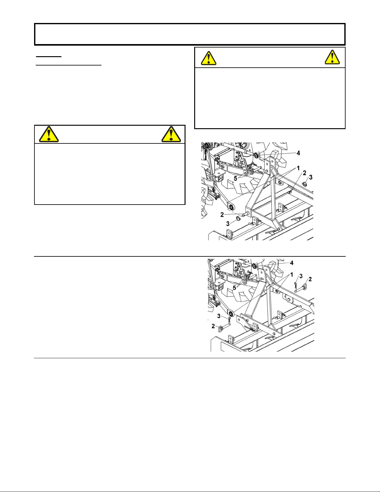
Mahindra BBSST4 User manual

1
READ&FOLLOWALLSAFETYRULES&INSTRUCTIONSBEFORE
OPERATINGYOUREQUIPMENT
108418-EN R-06012016
*ASSEMBLY *REPAIRPARTS
*OPERATION *MAINTENANCE
*107668*

2

3
TABLEOFCONTENTS
INTRODUCTION ...................................................................................................................................................... 1
SAFETYPRECAUTIONS ........................................................................................................................................ 2
SAFETYDECALS .................................................................................................................................................... 4
ASSEMBLY
Assemblyinstructions .................................................................................................................... 5
Step1 Hitchassembly ............................................................................................................................. 6
Step2 3Pointhookup.............................................................................................................................. 7
OPERATION&TRANSPORTATION ..................................................................................................................... 8
ADJUSTMENTS ....................................................................................................................................................... 10
MAINTENANCE&STORAGE ................................................................................................................................. 11
PARTSBREAKDOWNANDPARTSLIST .............................................................................................................. 12
TORQUESPECIFICATIONTABLE ....................................................................................................................... 36
PAGE

1
INTRODUCTION
TO THE PURCHASER
This new accessory was carefully designed to give years of dependable service. This manual has been provided to
assist in the safe operation and servicing of your attachment.
NOTE:
All photographs and illustrations in the manual may not necessarily depict the actual models or attachment, but
are intended for reference only and are based on the latest product information available at the time of publication.
Familiarize yourself fully with the safety recommendations
and operating procedures before putting the machine to
use. Carefully read, understand and follow these recommendations and insist that they be followed by those who will
use this attachment.
THIS SAFETY ALERT SYMBOL IDENTIFIES AN IMPORTANT SAFETY MESSAGE IN THIS
MANUAL THAT HELPS YOU AND OTHERS AVOID PERSONAL INJURY OR EVEN DEATH.
DANGER, WARNING, AND CAUTION ARE SIGNAL WORDS USED TO IDENTIFY THE LEVEL OF
HAZARD. HOWEVER, REGARDLESS OF THE HAZARD, BE EXTREMELY CAREFUL.
DANGER:
Signals an extreme hazard that will cause serious injury or death if recommended precautions
are not followed.
WARNING:
Signals a hazard that may cause serious injury or death if the recommended precautions are
not followed.
CAUTION:
Signals a hazard that may cause minor or moderate injury if the recommended precautions are
not followed.
Record your attachment serial number and purchase date in the section reserved below (there is no serial number on
the subframe). Your dealer requires this information to give you prompt, effi
cient service when ordering replacement
parts. Use only genuine parts when replacements are required.
If warranty repairs are required please present this registration booklet and original sales invoice to your selling dealer
for warranty service.
This manual should be kept for future reference.
Please check if you have received all the parts for your kit with the list of the
bag and the list of the box.
SERIAL NUMBER : ___________________________
(IF APPLICABLE)
MODEL NUMBER: ___________________________
PURCHASE DATE : ___________________________

2
SAFETYPRECAUTIONS

3

4
SAFETYLABELS
REPLACEIFDECALSAREDAMAGED
FORDECALLOCATIONSEEPARTLIST
DECAL#107650

5
ASSEMBLY
ASSEMBLYINSTRUCTIONS
IMPORTANT:UNLESSOTHERWISESPECIFIEDTORQUEALLBOLTSACCORDINGTOTORQUESPECI-
FICATIONTABLE(SEETABLEOFCONTENTS)WHENSTATED:TIGHTENFIRMLY.REFERTOPARTS
BREAKDOWNSECTIONFORPARTIDENTIFICATION.
Overallview
NOTE:Inthismanual,therightandleftsideisdeterminedbeingseatedonthedriver’sseatfacingforward.
Removetheboxscraperfromtheshippingcrate.
TRACTORREQUIREMENTS
TheBoxScraperwasdesignedfora3-pointcategory1hitch.TheSDmodelsareadaptedfortractorsbetween
17HP&35HP.TheHDmodelsareadaptedtotractorsbetween25HP&55HP.
SD6’Represented HD6’Represented

6
ASSEMBLY
FORTHESDMODEL
Attachtheleverarms(item1)fromthe3pointhitchto
theassembledboxscraperwiththepins(item3).
Attach the links (item 2)from the 3point hitch tothe
assembled box scraper with two 5/8’’ n.c. x 2’’ hex
bolts (item4) and twonylon insert lock nuts (item 5)
asshowninfigure1a.
Donottightenthenutsrightnow.
STEP1
HITCHASSEMBLY
FORTHEHDMODEL
Attachtheleverarms(item1)fromthe3pointhitchto
theassembledboxscraperwithtwo3/4’’n.c.x2’’hex
bolts(item3)andtwonyloninsertlocknuts(item4).
Attach the links (item 2)from the 3point hitch tothe
assembled box scraper with two hex 5/8’’ n.c. x 2’’
bolts (item5) and twonylon insert lock nuts (item 6)
asshowninfigure1b.
Donottightenthenutsrightnow.
Fig.1a
Fig.1b
FORTHESDMODEL
Aligntheholesinthelinkswiththeholesinthelower
holesintheleverarmsasshowninfigure2a.
With a sleeve (item 2) placed in the middle, insert a
hexbolt5/8’’n.c.x41/2’’(item1)andsecurewitha
nyloninsertlocknut(item3).
Whenhitchisinstalled,itwillformaA-frame.Make
suretheAframeispositionedperpendiculartothe
boxscraperandframe.
Tightentheboltsaccordingtotorquespecification
chart. Fig.2a
FORTHEHDMODEL
Aligntheholesinthelinkswiththeholesinthelower
holesintheleverarmsasshowninfigure2b.
With a sleeve (item 2) placed in the middle, insert a
hexbolt5/8’’n.c.x 41/2’’(item 1) and securewitha
nyloninsertlocknut(item3).
Whenhitchisinstalled,itwillformaA-frame.
Tightentheboltsaccordingtotorquespecification
chart.
Fig.2b

7
ASSEMBLY
STEP2
3POINTHOOKUP
IMPORTANT:
A3pointcategory1hitchisrequired.
Thelowerarmsofthe3pointhitchmustbestabilized
topreventsidetosidemovement.Mosttractorshave
swayblocksoradjustablechainsforthispurpose.
SlowlybackupthetractortotheBoxScraperanduse
thetractor’s3pointhydrauliccontrol.
Returntothetractorandslowlyoperatethetractor’s3
-point hydraulic control up and down to check for
clearancebetweentires,framedrawbar,etc.
Move or removethe draw bar if it interfereswith the
BoxScraper.
Manually adjust one of the two lower lift arms up or
downtoleveltheBoxScraperfromlefttoright.
Manually adjustthelengthofthetop-link tolevel the
BoxScraperfromfronttorear.
Ensurethatthelowerliftarmsareblockedtoprevent
excessivemovement.
DANGER
TOPREVENTINJURIES:
Hooking up equipment to the tractor is dangerous
and can result in serious injury or death. Do not
allow anyone to stand between the tractor and the
Box Scraper while backing up to the equipment. Do
not operate hydraulic 3-point lift controls while
someone is directly behind tractor or near the
scraper.
WARNING
TOPREVENTINJURIES:
Parkthevehicleonaflatsurfaceinawellventilated
area.
DisengagetheP.T.O.
Applyparkingbrake.
Stoptheengineandremovetheignitionkey.
Wait until all moving parts have stopped before
leavingthedriver’sseat.
FORSDMODEL
Attachtractor’slowerarms(item1) onthepins(item
2)andsecurewithlynchpins(item3)
Connect top center link (item 4) to the upper hitch
usingapinandhairpin(item5)asshowninfigure3a.
Fig.3a
FORHDMODEL
Attach tractor’s lower arms (item 1) to frame of
assembled box scraper with two pins (item 2) and
securewithlynchpins(item3)
Connect top center link (item 4) to the upper hitch
usingapinandhairpin(item5)asshowninfigure3b.
Fig.3b

8
OPERATION&TRANSPORTATION
DANGER
TOPREVENTINJURIES:
Make adjustments to box scraper after it has been
properlyattachedtotractorand secured with solid
supports.
Never work around or under equipment supported
onlybyhydraulics.
Hydraulics can drop equipment instantly if controls
are actuated or if hydraulic lines burst even when
powertohydraulicisshutoff.
DANGER
TOPREVENTINJURIES:
Never allow riders including children on the tractor or
scraper.Theycanfallandberanovercausingserious
injuryordeath.
WARNING
TOPREVENTINJURIES:
It is the operator’s responsibility not to allow anyone
neartheBoxScraperduringit’soperation.
WARNING
TOPREVENTINJURIES:
Do notalter the box scraper. Altering the scraper can
affectitsperformanceandreliabilitycausingdamageto
the scraper, tractor and/or injury. Always replace
damagedpartswithoriginalmanufacturerparts.
CAUTION
TOPREVENTINJURIES:
Always keep your feetand/or legs out from under the
shanks while adjusting them. It is possible for the
shankstofallcausinginjurytoyourfeetand/orlegs.
WARNING
TOPREVENTINJURIES:
Use the box scraper for it’s intended purpose only.
Neverusetheboxscrapertopull,lift,toworcarryother
equipment or objects. Doing any of the above could
resultindamagetothescraper,seriousinjuryordeath.
CAUTION
TOPREVENTINJURIES:
Be sure you are not working over any underground
wiring,pipesorotherobstructions.Ifthereisanydoubt,
callyourlocalutilityservicessotheymaydeterminethe
locationtoanyundergroundutilitiesinthearea.Besure
to ask how close you can work to the marks or flags
theypositioned.
WARNING
TOPREVENTINJURIES:
Donotallowanyonetooperatetheboxscraperwhois
undertheageof16orhasnotbeenproperlytrainedin
safeoperation.Allowingsomeonewhoistoo youngor
not properly trained to operate the box scraper could
result in damage to the box scraper, serious bodily
injuryordeath.

9
OPERATION&TRANSPORTATION
GENERALOPERATINGINSTRUCTIONS
Once you have familiarized yourself with the
Operator’sManual,properlyattachtheboxscraperto
thetractor.
Box scrapers are ideal for ripping, levelling finish
grading and back filling applications at feed lots,
outdoor arenas, building sites and maintenance
operationsonfarmorranchlanes,orroadways.You
checkoutyourworksiteforanyburiedutilitycables,
pipelines or other obstacles that you do not want to
damageorencounter.
The Box Scraper’s primary purpose is grading and
levelling.Thisfunctionisbestdoneatanapproximate
speedof2to4mph.Withtherippershanksraisedall
the way up, simply lower the Box Scraper to the
ground and drive forward. The grader blade should
immediatelybeginshavingthesoilsurfaceanddirtor
aggregate materialshould begin accumulating in the
box.
Youcantransferthismaterialbydraggingtoanearby
location and then raising the Box Scraper to deposit
yourload.Youcanalsoachieveauniformsurfaceby
using the Box Scraper to shave off high spots,
allowing accumulated matter to flow out under the
graderbladeinlowspots.Occasionallythegroundor
surface material will be very hard and will require
ripping toloosen the soil in order for BoxScraper to
beeffective.
Ifamoreaggressive rippingaction isrequired,lower
the shanks by 1.5” at a time. If less ripping is
required, raise all the shanks. It will require a little
experimentation and experience to achieve the
desiredeffectin yourgivenconditions.BoxScrapers
generally perform better in dry to slightly damp soil
conditions.
The Box Scraper can also be used for backfilling
applications.
SimplylowertheBoxScraperandbackthestandard
rear facing grader blade in to the pile of dirt you are
using for backfill. Continue backfilling and pushing
operationsuntilyouhavecompletedthetask.
WARNING
TOPREVENTINJURIES:
When traveling on public roads, use accessory lights,
SMVsign,cleanreflectorsandotheradequatedevices
to warn operators in other vehicles of your presence.
Always comply with all federal, state, provincial and
locallaws.
Be sure to reduce tractor speed when turning, and
leaveenoughroomforclearancesotheBoxScraper
does not contact obstacles such as buildings, trees,
orfences,etc.
Select a safe travel speed when transporting from
oneareatoanother.
Whentravelingonroadways,travelinsuchawaythat
fastermovingvehiclesmaypassyousafely.
Whentravelingoverroughorhillyterrainshifttractor
tolowergear.
Watch out for fences, trees, rocks, wires while
operatingandtransportingtheattachment.
TRACTORSHUTDOWN&STORAGE
DisengagethePTOofthetractor.
Lowerthe attachment tothe ground, engage parking
brake, turn off engine and remove the switch key to
preventunauthorizedstarting.
Wait for all moving parts to come to a stop before
leavingthedriver’sseat.
Detach and store the accessory in an area where
children do not normally play. Secure the accessory
usingblocksandsupports.
WARNING
TOPREVENTINJURIES:
Turning the tractor too tight may cause hitched
accessories to ride up on the wheels. This could
resultininjuryand/orequipmentdamage.

10
ADJUSTMENTS
DANGER
TOPREVENTINJURIES:
Make adjustments to Box Scraper after it has been
properlyattachedtotractorand secured with solid
supports.
Never work around or under equipment supported
onlybyhydraulics.
Hydraulics can drop equipment instantly if controls
are actuated or if hydraulic lines burst even when
powertohydraulicisshutoff.
Shank settings are based on the vertical distance
measured frombottom edge of sideplatesto bottom
ofshanktips.Adjusteachshankheightasfollows.
Removehairpin(item2)andpin(item1).
Adjustshank(item3)upordowntothedesiredhole
setting,thenreplacepinandsecurewithhairpin.
Withshanksraisedfullyup,parkthetractorandBox
Scraperonaflatlevelsurface,thenlowerscraperon
thelevelsurface.
SHANKADJUSTMENT
LEVELINGANDPITCHADJUSTMENT
CAUTION
TOPREVENTINJURIES:
Parkthevehicleonaflatsurfaceinawellventilated
area.
DisengagetheP.T.O.
Applyparkingbrake.
Stoptheengineandremovetheignitionkey.
Wait until all moving parts have stopped before
leavingthedriver’sseat.
CAUTION
TOPREVENTINJURIES:
Always keep your feetand/or legs out from under the
shanks while adjusting them. It is possible for the
shankstofallcausinginjurytoyourfeetand/orlegs
PlacealevelonthelongerfrontShankBar.
Manually adjusteither one or both of the tractor’s 3-
pointarmupor downtolevelthescraperfromleftto
right. Some tractors have only one arm that is
adjustable.
Rotate the level 90 degrees and adjust the tractor's
topcenterlinkuntilitislevelledfromfronttoback.
NOTE:
Ifneeded,shortenthetopcenterlinkone-halfturnat
atimetoincreasebladepitch.

11
MAINTENANCE&STORAGE
ALWAYSPRACTICESAFEMAINTENANCE
Always understand the procedures before doing any
work. Use the proper tools and equipment, refer to
theOwner’smanualforadditionalinformation.
Alwaysworkinacleandryarea.
Do not grease or oil the accessory while it is in
operationunlessotherwisespecified.
Inspect all parts. Make sure parts are in good
condition&properlyinstalled.
Removeanybuild-upofgrease,oilordebris.
Remove all tools and unused parts from accessory
beforeoperating.
Properservicingandadjustmentsarethekeytolong
life of any accessory. With careful inspection and
routinemaintenanceyoucanavoidcostlyrepairsand
delays.
Checkalltheboltsafterusingtheunitforafewhours
tobesuretheyaretight.Replaceworn,damaged,or
illegible safety labels by obtaining new labels from
yourdealer.
ThepartsonyourBoxScraperhavebeenspecifically
designed and should only be replaced by genuine
manufacturer’sparts.
Donotalterthescraperinanywaythat willaffectits
performance.
SHANKTIPS
Shank tips are removable by heating them in the
dimpled area on both sides and knocking them off
withabluntpunch.
Newshanktipsneedtobedimpledwithapunchafter
theyhavebeeninstalled.
STORAGE
Clean, inspect, service and make necessary repairs
to the Box Scraper when parking it for long periods
and when parking it at end of working season. This
willensurethatthescraperisreadyforusenexttime
youneedit.
Cleanoffanydirtthatmayhaveaccumulatedonthe
scraper and cutting blade. Scrape off compacted dirt
andthoroughlyrinsewithagardenhose.
Check shank bars and bolts for wear and replace if
necessary. For more information, see Cutting blades
sectiononthispage.
Inspect Box Scraper for loose, damaged, or worn
parts. Adjust and tighten loose parts. When needed
replacepartswithgenuinemanufacturer’sparts.
Repaint parts where paint is worn or scratched to
preventrust.
Replacealldamagedormissingdecals.
Store Box Scraper on a level surface in a clean dry
place. Inside storage will reduce maintenance and
makeforalongerlifespan.
GRADERBLADES
The front and rear grader blades have two cutting
edges. Replace grader blades when both edges are
wornout.
Unbolt grader blade and turn it over when its bottom
cuttingedgewearsout.
Inspect the 5/8’’-11 x 1 1/2’’ bolts and hex. nuts for
wear.Replaceasneeded.
Reattachbladeandnuts.Tightenaccordingtotorque
specificationtable.
WARNING
TOPREVENTINJURIES:
Lower the attachment to the ground, put tractor in
park, turn off the engine and remove key before
doinganymaintenance.
Lettheaccessorycoolbeforedoinganyworkonit.
Disconnect the battery ground cable (-) before
servicing or adjusting electrical systems or before
weldingontheaccessory.

12
BBSST4
BBSST4

13
O/L=Obtainlocally
BBSST4
BBSST4

14
NOMENCLATUREETLISTEDESPIÈCES/PARTSBREAKDOWN&PARTLIST
BOÎTENIVELEUSESD4’ASSEMBLÉE#501358
BOXSCRAPERSD4’ASSEMBLY#501358

15
O/L=Obtainlocally

16
BBSST5
BBSST5

17
O/L=Obtainlocally
BBSST5
BBSST5
This manual suits for next models
5
Table of contents
Other Mahindra Farm Equipment manuals
Popular Farm Equipment manuals by other brands

Plotmaster
Plotmaster Hunter 600 user manual

WALTERSCHEID
WALTERSCHEID CONNECTED SERVICE COUNTER Assembly and installation instruction

Pottinger
Pottinger NOVADISC 732 Operator's manual

aivituvin
aivituvin AIR 38 instruction manual

Nedap
Nedap VP1004-B instruction manual

Kverneland
Kverneland PL operating manual

J&M
J&M HT-974 manual

Kverneland
Kverneland Exacta-TL-GEOSPREAD GS3 Operator's manual

Toro
Toro 41355 manual

EASY COOPS
EASY COOPS Chicken Coop Plan 20x40 Assembly instructions

AHRENS AGRICULTURAL INDUSTRIES
AHRENS AGRICULTURAL INDUSTRIES E-Fount MIRACO 3410-4E installation instructions

Dadant
Dadant M59601 Assembly instructions