Sulky Burel X40+ ISOBUS User manual

TECHNICIAN’SOPERATING MANUAL
X40+X50+ISOBUS
Réf 400 915-03 EN / DIS

NAME: TRAINING DEPARTMENT DATE : 2017 PAGE : 2 / 59
REFERENCE: TECHNICIAN’SOPERATING MANUAL X40+-X50+ ISOBUS IND 03
++
5
-
CONTENTS
To comply with the instructions for safety and use, refer to the instruction manuals corresponding to the
fertilizer spreader and the electronic console.
3-50 I -SPECIFICATION SHEETS
51-57 II -DIAGNOSTIC PROCEDURES
Pages

NAME: TRAINING DEPARTMENT DATE : 2017 PAGE : 3 / 59
REFERENCE: TECHNICIAN’SOPERATING MANUAL X40+-X50+ ISOBUS IND 03
++
5
-
I - SPECIFICATION SHEETS
SHEET NO.SPECIFICATION SHEETS PAGE NO.
A1 Global view 4 - 5
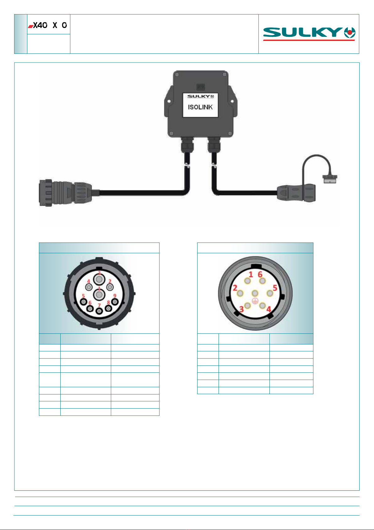
A2 ISOLINK wiring bundle 6
A3 ECU - CAN connection box 7
B1 Regulator settings check 8
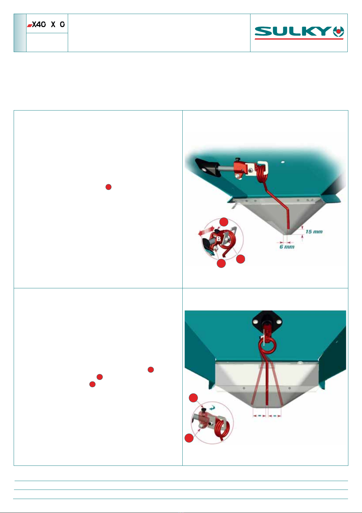
B2 Mechanical calibration of the shutters 9
B3 Mechanical calibration of the chutes 10
B4 Calibration of application rate and width actuators 11
B5 Shutter guides settings 12
C1 Calibration of the weighing device 13
C2 Angle sensor of the weighing device 14
C3 Weighing blades check 15
C4 Replacement of weighing blades 16 -17
C5 Pre-tensioning spring dimension inspection 18
C6 Weighing sensor 19 - 20
D1 Electrical application rate actuators 21 - 23
D2 Tribord actuators 24 - 26
D3 Chute actuators (Width) 27 - 29
D4 Stop & Go actuators 30 - 31
D5 Shutter sensors 32
D6 End of hopper sensors 33
D7 ECU (Electronic Control Unit) 34 - 35
E1 Diagnostics Menu 36
E2 Machine History 37
F1 Retrieve the data from an ISOLINK 38 - 40
F2 Perform an ISOLINK RESET 41
F3 Set up the ISOLINK 42 - 46
F4 Updating the ISOLINK software 47 - 48
H1 FERTITEST import 49 - 50

NAME: TRAINING DEPARTMENT DATE : 2017 PAGE : 4 / 59
REFERENCE: TECHNICIAN’SOPERATING MANUAL X40+-X50+ ISOBUS IND 03
++
5
-
GLOBAL VIEW
A1.1
1
2
3
4
5
1
10
6
8
1
12
1
14
1
16
1
15
1
17
1
18
7
9
1
11
1
13

NAME: TRAINING DEPARTMENT DATE : 2017 PAGE : 5 / 59
REFERENCE: TECHNICIAN’SOPERATING MANUAL X40+-X50+ ISOBUS IND 03
++
5
-
GLOBAL VIEW
A1.2
MARKERS NAMES PART REFERENCES
1
ISOBUS UNIVERSAL TERMINAL -
2
ISOBUS TRACTOR WIRING BUNDLE -
3
GPS ANTENNA -
4
ISOLINK 983845
5
ECU - CAN CONNECTION BOX
CONNECTION BOX : 721989
CABLE: 721990
6
LEFT END OF HOPPER SENSOR
983917
7
RIGHT END OF HOPPER SENSOR
8
LEFT TRIBORD ACTUATOR
911038
9
RIGHT TRIBORD ACTUATOR
1
10
LEFT-HAND CHUTE ACTUATOR (WIDTH)
911037
1
11
RIGHT-HAND CHUTE ACTUATOR (WIDTH)
1
12
LEFT-HAND APPLICATION RATE ACTUATOR
1
13
RIGHT-HAND APPLICATION RATE ACTUATOR
1
14
LEFT-HAND SHUTTER OPENING ILS SENSOR
983912
1
15
RIGHT-HAND SHUTTER OPENING ILS SENSOR
1
16
STOP & GOLEFT-HAND ACTUATOR (SHUTTER OPENING)
982508
1
17
STOP & GORIGHT-HAND ACTUATOR (SHUTTER OPENING)
1
18
WEIGHING SENSOR 983920

NAME: TRAINING DEPARTMENT DATE : 2017 PAGE : 6 / 59
REFERENCE: TECHNICIAN’SOPERATING MANUAL X40+-X50+ ISOBUS IND 03
++
5
-
ISOLINK WIRING BUNDLE
A2
ISOBUS MALE PLUG
PIN COLOUR FUNCTION
1BLACK + WHITE 0 V – 60 A
2BLUE 0 V – 25 A
3RED + BROWN +12 V – 60 A
4PURPLE +12 V – 25 A
5LINK TO PIN NUMBER 4
RELAY CONTROL OF
TERMINATON
6NC
7NC
8YELLOW CAN HI
9GREEN CAN LO
ECU FEMALE SOCKET
PIN COLOUR FUNCTION
1RED + 12 V
2BROWN +12 V
3WHITE 0 V
4PURPLE CONTACT ECU
5GREEN CAN LO
6YELLOW CAN HI
7BLACK 0 V

NAME: TRAINING DEPARTMENT DATE : 2017 PAGE : 7 / 59
REFERENCE: TECHNICIAN’SOPERATING MANUAL X40+-X50+ ISOBUS IND 03
++
5
-ECU - CAN
CONNECTION BOX
A3
LEFT-HAND
APPLICATION RATE
RIGHT-HAND
APPLICATION RATE
RIGHT-HAND CHUTE
TRIBORD
RIGHT-HAND STOP & GO
RIGHT-HAND SHUTTER
SENSOR
LEFT-HAND CHUTE
LEFT-HAND
STOP & GO
LEFT TRIBORD
YELLOW
GREEN
PURPLE
BLACK
BLUE
BROWN
RED
WHITE
RED
BLUE
WHITE
RED
BLUE
WHITE
RED
BLUE
BLACK
RED
BLUE
BROWN
BLUE
BLACK
BLACK
BLUE
BLUE
BLACK
BLACK
RED
BLUE
BROWN
BLUE
RED
RED
WHITE
WHITE
BLUE
BLACK
RED
WHITE BROWN
YEL/GRE
BLACK
BLUE/
GREY
WEIGHING
SENSOR
LEFT-HAND SHUTTER
SENSOR
BROWN
YEL / GREEN
BLUE
BROWN
YEL / GREEN
BLUE
LEFT END OF
HOPPER SENSOR
RIGHT END
OF HOPPER
SENSOR

++
5
-
REGULATOR SETTINGS CHECK
B1
NAME: TRAINING DEPARTMENT DATE : 2017 PAGE : 8 / 59
REFERENCE: TECHNICIAN’SOPERATING MANUAL X40+-X50+ ISOBUS IND 03
The regulators encourage the ow of the product through the shutters.
An incorrect adjustment of the regulators may cause a dierence between the right-hand and the left-hand application rate. This means
that when working, the spreader is emptied faster on one side than on the other.
If this is the case, the following settings must be checked.
ᇗ
Make sure the space between the tip of the regulator and the
bottom of the bowl is 15 mm.
When this is the case, lock screw
3
.
ᇗ
The tip of the regulator must be 6 mm from the opening of the
shutter, on the at bottom of the bowl.
To reach this, slide the support on the shaft
ᇗ
The sweeping of the tip must be symmetrical in relation to the
application rate opening.
Adjustment is made by rotation on the shaft.
ᇗ
When the unit is in place, begin by moving screw
1
closer to
the shaft; then tighten screw
2
.
Finish tightening of screw
1
.
What is most important is that the settings of the two regulators
must be absolutely identical.
1
3
2
1
2

NAME: TRAINING DEPARTMENT DATE : 2017 PAGE : 9 / 59
REFERENCE: TECHNICIAN’SOPERATING MANUAL X40+-X50+ ISOBUS IND 03
++
5
-MECHANICAL CALIBRATION
OF THE SHUTTERS
B2
ᇗ
With the spreader empty and the Stop & Go shutters open.
ᇗRemove the shaft of the application rate electric actuators.
ᇗPlace a Ø 35 mm round bar
1
in the shutter opening (towards the front). Then lower the shutter using the lever.
ᇗ
The Ø 35 mm round bar must be in contact with the bottom and the front of the opening and touch the plastic shutter.
Under these conditions the index of the application rate lever must be at mark 49
2
ᇗIf this is not the case, the index is mounted on slot
3
, and therefore it must be moved in front of mark 49.
ᇗPerform this adjustment identically on both sides
2
3
1

NAME: TRAINING DEPARTMENT DATE : 2017 PAGE : 10 / 59
REFERENCE: TECHNICIAN’SOPERATING MANUAL X40+-X50+ ISOBUS IND 03
++
5
-MECHANICAL CALIBRATION
OF THE CHUTES
B3
ᇗRemove the shaft
1
of the electric actuators on the chute side.
ᇗAlign the chute with the notch in the centre of the spreading disc
2
.
ᇗ
The index
3
must point to mark 137. If this is not the case loosen the screws
4
and align the index in front of mark 137. Tighten
the screws
4
again.
ᇗPerform this adjustment identically on both sides.
ᇗ
Following this adjustment, you must continue with the electrical setting.
(Only on )
3
4
1
2

NAME: TRAINING DEPARTMENT DATE : 2017 PAGE : 11 / 59
REFERENCE: TECHNICIAN’SOPERATING MANUAL X40+-X50+ ISOBUS IND 03
+
ᇗOn the universal terminal, access the menu ADVANCED SETTINGS.
Select "Capteurs et actionneurs" (Actuators and sensors)
Enter the PIN code 1936 and conrm.
Using display the page "Réglage Vérins" (Actuator Setup)
Press
The terminal is displayed:
"Vérins Réglés" (Actuators Adjusted)
1- Application rate electric actuators :
The index of the application rate levers must be on mark 35
1
If this is not the case, the lower attachments of the actuators
2
must be adjusted (presence of adjustment slots).
2- Width electric actuators (Chutes) :
(Only on )
The index of the width levers must be on mark 137
1
If this is not the case, the attachments of the actuators
2
must be adjusted (presence of adjustment slots).
+
5
-CALIBRATION OF APPLICATION RATE
AND WIDTH ACTUATORS
B4
ᇗFirst make sure the mechanical calibrations of the shutters to mark 49 and of the chutes to mark 137 are correct.
Shutter calibration, see Sheet B2
Chute calibration; see Sheet B3 (Only on )
1
2
1
2

NAME: TRAINING DEPARTMENT DATE : 2017 PAGE : 12 / 59
REFERENCE: TECHNICIAN’SOPERATING MANUAL X40+-X50+ ISOBUS IND 03
++
5
-
SHUTTER GUIDE SETTINGS
B5
When a shutter guide
1
is too tight, it can cause jamming at a shutter opening, before it comes
to a stop with its application rate lever
2
.
ᇗCheck there is a 1 mm clearance between the bowl and the shutter with the spreader loaded.
ᇗ
To adjust:
1. Remove the H6 nut of the anti-bounce device
3
2. The shutter guide is mounted on a slot. Using screws
4
and
5
set a 1 mm clearance between the shutter and the bottom of
the metering mechanism. It is preferable to make a slightly bigger adjustment for the upper section
5
.
3. Put back the anti-bounce device and its nut
3
.
1
2
3
5
4

NAME: TRAINING DEPARTMENT DATE : 2017 PAGE : 13 / 59
REFERENCE: TECHNICIAN’SOPERATING MANUAL X40+-X50+ ISOBUS IND 03
++
5
-CALIBRATION
OF THE WEIGHING DEVICE
C1
The weighing device allows a tolerance margin of 3%. If you notice a weight dierence between the control unit information and the real
weight, you can calibrate the weighing device sensor. To calibrate the weighing device sensor follow the procedure below. In order to be
able to calibrate the sensor, load a known weight into the hopper. (The weight must be a minimum of 1000 kg).
The reference weight must be accurate in order to obtain a good result.
ᇗOn the universal terminal, access the ADVANCED SETTINGS menu
Select "Calibration pesée" (Weight calibration)
Enter the PIN code 1234 and conrm.
ᇗEnter the actual weight and select the corresponding eld
ᇗThe software calculates the error percentage.
ᇗConrm the calibration with the key
Press ESC and return to the HOME page
The weighing device is calibrated

NAME: TRAINING DEPARTMENT DATE : 2017 PAGE : 14 / 59
REFERENCE: TECHNICIAN’SOPERATING MANUAL X40+-X50+ ISOBUS IND 03
++
5
-
WEIGHING DEVICE ANGLE SENSOR
C2
The ECU connection box has an inclinometer which continuously measures the slope of the fertilizer spreader.
This measurement enables the weighing device to be corrected depending on the angle of the machine.
An incorrect calibration distorts the display of the weight.
Angle sensor calibration
Position the spreader perfectly level both
front/rear and left/right
ᇗOn the universal terminal, access the menu ADVANCED SETTINGS .
Select "Capteurs et actionneurs" (Actuators and sensors)
Enter the PIN code 1936 and conrm.
Using display the page "Capteur d’angle" (Angle sensor)
Once the spreader is level press the key
The values should become 0°

NAME: TRAINING DEPARTMENT DATE : 2017 PAGE : 15 / 59
REFERENCE: TECHNICIAN’SOPERATING MANUAL X40+-X50+ ISOBUS IND 03
++
5
-
WEIGHING BLADES CHECK
C3
If the weight displayed on the console for a similar weight is highly random, you must check that there is no friction or foreign bodies
between the weighing device frame and the spreader chassis.
If there is friction on the frame, the tightening of the screws and the condition of the spring blades must be checked.
Screws are tightened to 18 daN.m.

NAME: TRAINING DEPARTMENT DATE : 2017 PAGE : 16 / 59
REFERENCE: TECHNICIAN’SOPERATING MANUAL X40+-X50+ ISOBUS IND 03
++
5
-REPLACEMENT
OF THE WEIGHING BLADES
C4.1
It is essential for the spreader to be unhitched and on its stands.
It is recommended that you have a socket for size 14 hexagon socket screws (e.g. reference STM.14)
1- Place a nut on the pressure screw to compress the pre-tensioning spring.
2- Make sure the 2 safety stops are present
3- Unscrew the 16 x 65 stainless steel screws of the lower blades for dismantling.
2
1
3

++
5
-REPLACEMENT
OF THE WEIGHING BLADES
C4.2
4- Position a 16 x 100 screw on each side to secure the unit.
5- Remove the upper blades
6- Assembling double blades.
For the complete replacement of the weighing blades,
you must order: 4 kits, 911035.
Every kit consists of:
4 HSHC screws, 16 x 65, 2 threaded plates, 4 locknuts,
4 x W16 stainless steel washers, 4 x M16 washers and 2 spring blades.
7- Following the replacement of the parts, rst reassemble the upper blades without locking the screws.
Then, at the lower level, remove the 16 x 100 safety screws and mount the new blades without locking the screws.
8- Centre the triangle so there is no friction and secure the screws to 18 daN.m.
9- Remove the nut on the pressure screw.
10- Check the dimension of the spring on the pressure screw: 67 to 71 mm. (See sheet C5)
11- Perform a calibration of the weighing device. (see sheet D1)
4
5
6
Assembling double blades
NAME: TRAINING DEPARTMENT DATE : 2017 PAGE : 17 / 59
REFERENCE: TECHNICIAN’SOPERATING MANUAL X40+-X50+ ISOBUS IND 03

NAME: TRAINING DEPARTMENT DATE : 2017 PAGE : 18 / 59
REFERENCE: TECHNICIAN’SOPERATING MANUAL X40+-X50+ ISOBUS IND 03
++
5
-PRE-TENSIONING SPRING
DIMENSION INSPECTION
C5
An incorrect adjustment of the pre-tensioning spring may cause poor stability of the weight displayed.
(Inspection and adjustment to be performed when the spreader is unhitched)
A- Checking the dimension of the spring
Check that screw (A) is resting on the weight indicator with the machine unhitched.
B- Adjusting the pre-tensioning of the spring
If the dimension of the spring is not correct, you must adjust the clamping
screw at the weight indicator to compress or release the spring
1- Place a nut
1
on the pressure screw to compress the spring to height
67 < 71 mm.
2- Unscrew the cone-point set screw
2
3- Adjust the H20 clamping screw
3
until it comes into contact with the
weight indicator, and the pressure screw in contact with its support.
4- Tighten the cone-point set screw
2
5- Remove the nut on the pressure screw.
6- The calibration of the weight indicator is compulsory after this
operation. (See sheet C1 )
1
2
3
A

NAME: TRAINING DEPARTMENT DATE : 2017 PAGE : 19 / 59
REFERENCE: TECHNICIAN’SOPERATING MANUAL X40+-X50+ ISOBUS IND 03
++
5
-
WEIGHING DEVICE SENSOR
C6.1
1- Characteristics of the weighing device sensor:
The weight information is obtained from a strain gauge.
The ECU supplies a stabilized voltage of 5.00 volt to the weight indicator.
The sensor returns a voltage in mV which varies depending on the load.
2- Checking the supply voltage:
Check the voltage between the terminals of the brown wire and the blue
wire.
A stable voltage of 5.00 V should be measured
WIRE COLOUR FUNCTION
BROWN + 5 V
BLUE 0 V
YELLOW GREEN + V SIGNAL (MV)
BLACK 0 V SIGNAL
GREY SCREEN
3- Weighing device settings:
On the universal terminal, access the menu ADVANCED SETTINGS .
Select "Capteurs et actionneurs" (Actuators and sensors)
Enter the PIN code 1936 and conrm.
Using display the page "Capteur pesage" (Weighing Cell)
In case of a malfunction of the weighing device, these values must be checked :
ᇗ
Tare point between 0.5 and 2 ᇗHigh point between 1100 and 1400.
If the values are outside these limits, enter the average values:
ᇗ
Tare point: 1.02 ᇗ
High point: 1261.00
It is then necessary to perform a calibration of the weighing device (see sheet C1) to restore the accuracy
Weighing sensor reference :983920

++
5
-
WEIGHING DEVICE SENSOR
C6.2
Checking the weighing device sensor is only carried out after a positive diagnosis of the link between the CAN and ECU and a weight
indicator supply voltage.
1- When checking the sensor the spreader must be unhitched.
2- Place a nut on the pressure screw
1
to compress the spring so there is no
strain on the weighing beam.
3- Completely disconnect the weight indicator in the connection box
2
and
uncouple the grey wire from the blue wire
4- Check the values opposite.
The weighing device sensor is considered to be compliant if it meets all these
indications.
SENSOR BRAND VISCHAY
R BETWEEN THE BROWN
AND BLUE WIRES 385 Ω +/- 10
R BETWEEN THE GREEN/
YELLOW AND BLACK WIRES 353 Ω +/- 3
R BETWEEN THE GREY WIRE
AND EACH OF THE 4 OTHER
WIRES
NOCONTINUITY
1
2
NAME: TRAINING DEPARTMENT DATE : 2017 PAGE : 20 / 59
REFERENCE: TECHNICIAN’SOPERATING MANUAL X40+-X50+ ISOBUS IND 03
This manual suits for next models
1
Table of contents
Other Sulky Burel Farm Equipment manuals
Popular Farm Equipment manuals by other brands

Amazone
Amazone AD-P 3001 Special 850 operating manual

Reflex Marine
Reflex Marine WAVE4 user manual

Blue Diamond
Blue Diamond Extreme Duty Root Grapple Operation and maintenance manual

Metalcraft
Metalcraft SCAG GIANT-VAC TL20W-29BV Operator's manual

Tube-Line
Tube-Line Boss R 4520 Operator's manual

FARM SCAN
FARM SCAN canlink 3500 Operator's manual