Forte A-BUS/DIRECT ABD-C6 Instruction Manual

The ABD-C6 is a pair of speakers with one speaker as the master (right
channel) and has the A-BUS amplier mounted on the back plus an infrared
receiver for system control (volume level, ON/MUTE and source control)
mounted behind a red lens on the front. The passive speaker is connected
to the A-BUS amplier via a 5m (15’) connecting cable (supplied). Only
one Cat-5 cable is required from the hub directly to the speaker location
terminated with an RJ45 plug.
Infrared Repeater: A-BUS/direct Speakers will pass most infrared
commands without difculty. They will repeat standard 38 kHz commands
and 56 kHz commands which are often used in satellite receivers. Care
should be taken to ensure the emitters are properly placed over the receiver
on the front of the source component/s.
Remote IR Range: The operating range of your Remote Control will vary
according to the light conditions in the room, the quality of the IR remote
(and battery condition) and the system design in the components. In ideal
conditions in areas with low light the range should be up to 30m (100ft)
on axis; however, in areas of high sunlight or lighting such as low-voltage
lighting which can emit light in the infrared frequency range the operating
range can be substantially less. In direct sunlight the range may be reduced
to as little as 5m (15ft). Care should be taken when planning your A-BUS
system installation to locate the A-BUS/direct Speakers in a position away
from direct light and in a position convenient to the users to point the IR
Remote Control to the receiver in the module.
Note: Remote controls are not RF devices. The commands are sent by line-
of- sight and will not go around corners or work if there are any obstructions
between the remote and the receiver.
Trim Pots: (left and right) are included on the amplier board that ne-tune
the output level to compensate for the length of the cable run, the efciency
of the speakers and the size of the room. There are also situations where
you may want to limit the output level in a particular room. With the trim
pots adjusted to minimum, the main volume control should be adjusted to
maximum level, then with popular music playing the trim pots should be
Installation Guide / Warranty Information
In-Ceiling Architectural Speakers
Welcome to Forté A-BUS Multi-Room Audio
We hope you enjoy your Forté A-BUS system. Your Forté A-BUS component
has been designed to give high quality sound, and is simple and functional to
operate. All Forté A-BUS products bearing the Forté A-BUS logo are made to the
A-BUS Standard, so when you connect a Forté A-BUS input device, hub, volume
control module or Forté A-BUS/direct speaker they are compatible with each
other. All Forté A-BUS components are simple to install, service or upgrade; thus
enhancing your system with components that offer improved features should be
easy.
When designing an audio system it is important to balance and match the quality
of the components. Forte’ A-BUS delivers high quality audio signal to every room
so it is important that the correct speaker match is made. Most in ceiling loud-
speakers look the same but their quality varies greatly. The ABD-C6 and ABP-C6
speakers have been specically designed for A-BUS to maximise performance and
to provide the reliability needed for rugged conditions.
PleaserefertoeachoftheindividualmanualsonA-BUS/readyampliers and A-
BUS hubs for further installation instructions.
Forté A-BUS/
direct
Installation
The A-BUS learning remote keypad with cradle includes the following
commands; Please refer to the ABR-43 Instruction
Manual for greater details.
1. Mode Buttons
2. Volume Buttons
3. Room On/Mute
4. System Mute
5. Coloured Buttons -
single command mode
6. Control Buttons
7. Talk Back LED
ABR-43 Operating Instructions
A-BUS/
direct
/ A-BUS/
passive
ABD-C6 / ABP-C6
hubs
modules
speakers
Cat5
2-Core
Forté A-BUS Multi-Source Hub
ZONE OUTPUT
ROUTED
IR
L R L R
ABX-88
1 2 3 4
TM
AUDIO IN
TALK
STATUS
COMMON IR
12V TRIGGER OUT
100mA
1
2
3
4
AUDIO OUT
DATA
EXPANSION
+24V
2.5A+ -
A
B
IN
OUT
DC1
DC2
N1787
SAT
Cat5
SOURCE1
SOURCE2
AMP
OUTPUT
INPUT
2-Core
LOCAL INPUT MODULE
brought up to a
point just below
the amplier’s
clipping level.
(Clipping is the
point where the
sound starts
to distort).
When the
trim pots are
all set to the
desired level the installation may be
completed.
Mono/Stereo: The A-BUS Direct
speaker is equipped with a Stereo/
Mono switch located on the cross
over (See Photo). This feature
allows you to use the speakers in
both a stereo or mono mode. The
stereo mode is used when both
the active and passive speakers
are located in the same room. The
mono mode provides stereo sound
at each speaker location similar
to a Dual Voice Coil speaker. The
mono mode is best used when the
speakers are used in a large room,
in a hallway, one set is used in
multiple areas such as bathrooms,
or multiple speakers are located in
the same room. In addition, if the
speakers are placed too close to
each other.
System Status Indicator: The
Red LED behind the red lens on
the front to the master speaker.
When the A-BUS system is active
it is on. If an infrared signal is
received it will ash.
Termination: RJ-45 as T568A .
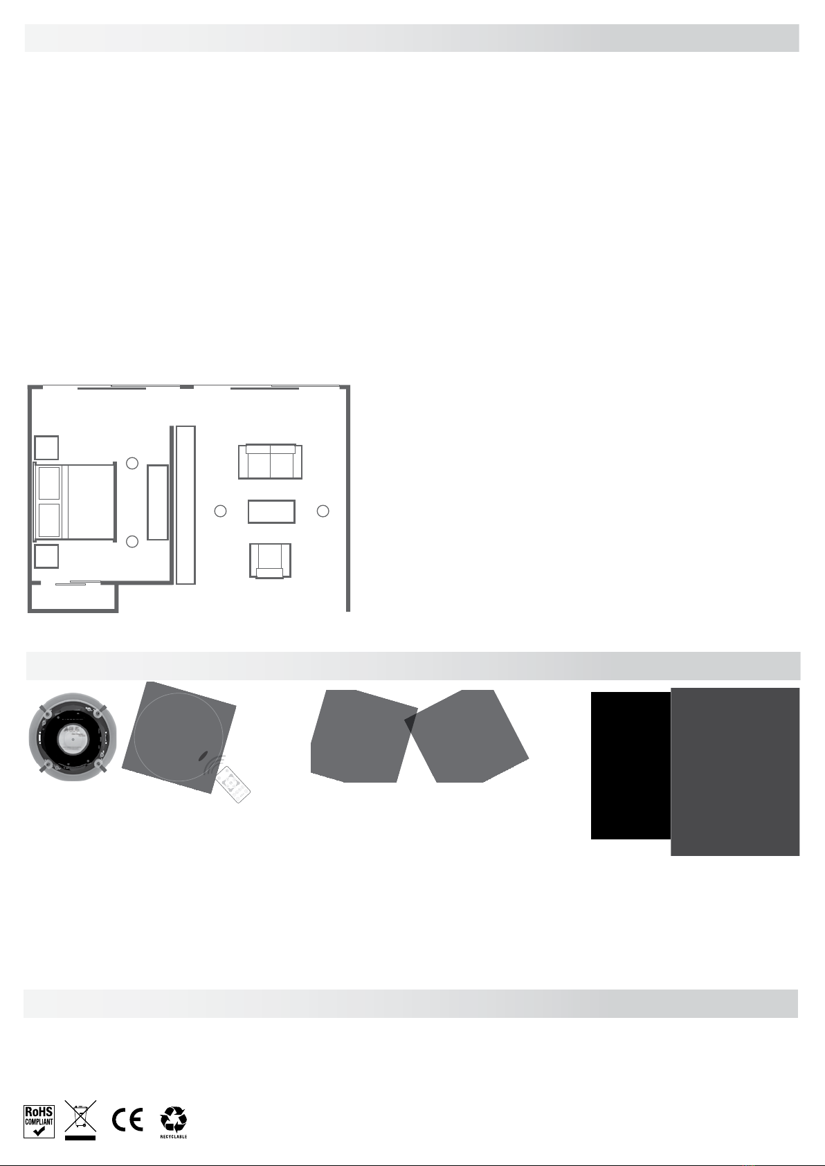
Forté A-BUS Speaker Installation
Acoustics The speakers should be mounted in a position that will provide a stereo
image to the main listening area in a room. They should not be directly above the
listeners or facing directly over hard or reective surfaces. In dining areas where
defused sound is preferred the speakers should be placed in diagonally opposite
corners (mono operation may be preferred). In outside locations the speakers
should be away from exposed locations, preferably under eves where the sound is
directed downward and not projected towards neighbour’s homes. Caution:water
surfaces reect sound.
Installing Check the preferred speaker location before cutting speaker holes in
the ceiling for wood studs, joists, and obstructions such as plumbing, heating
ducts or electrical wiring. If you are not sure of possible obstructions, cut a small
hole in the centre of your outline. This will allow you to check for obstructions.
The holes should be cut prior to painting of the room and the speaker should
only be installed during the nal t out. Excess dust and building material should
be removed from the area behind the speaker. Insulation material may be put
over the speaker; however, loose particles may fall into the drive and affect
the speaker’s performance. Use the supplied speaker cutout to get the correct
dimension of the hole needed for the speaker. When installing the cables make
sure there is extra cabling available (1m, 3’ minimum) at each end to make
connection to the terminals easy.
Speaker Painting: If your speakers are to be painted it should be done prior
to the installation. Paint guards are provided to cover the active parts of the
speaker. The grilles should be painted separately; care should be taken to
make sure the holes do not get blocked. Diluting the paint or automotive
spray painting normally provide the best results.
PreparingPassiveSpeakerCable:To prep for connection to the passive speaker,
strip back the outside insulation or sheathing so the individual conductors
are showing. Depending on the cable, there should be two or four separate
conductors. Strip back the insulation on each conductor to show the bare copper
wire. We suggest stripping enough so that 10mm of copper wire is showing.
Twist cable so there is not any loose wires. Push down each clip and insert the
speaker cable so it ts cleanly. The clips will be located on the back of the speaker
crossover. Make sure that only BARE wire is touching the speaker clip once it
slides back into place. All Forté A-BUS speakers feature spring clip terminals which
are quick and simple to use.
CAUTION: Make sure to observe speaker polarity, + to + and – to –. The – ground
terminal is normally black and the + is normally red. Incorrect wiring will reduce
sound quality and may damage the speakers.
A-BUS/directSpeakers: Make sure the speaker cable between the master driver and
the passive driver is installed when the speaker holes are cut. If a longer length is
required use 14 to 18 gauge twin core copper cable
When connecting the other end of the speaker cable to the amplier or receiver,
make sure to observe the same polarity as you did at the speaker connection.
To prepare the speaker for the actual installation, turn all the mounting toggles
(dog ears) in toward the speaker frame. This will allow the speaker to easily t
into the precut hole. Put the speaker into the hole (the speaker cable should be
connected) and make sure the speaker cable stays connected to the speaker.
Carefully tuck the speaker cable up into the hole as you put the speaker into
place. Hold it in place with one hand and with your other hand carefully tighten
the mounting screws evenly to secure the speaker. As you tighten the screws, the
dog ears will ip into position to grip into the drywall. DO NOT over tighten the
mounting screws. This will cause damage to the mounting toggle and the speaker
will not stay in place.
Grille Installation: ABD-C6 grille requires alignment of the lens with the IR sensor
on the speaker. Align the grilles edges to the groove on the speaker and carefully
push the grille on. Make sure to check all the way around the grille to ensure its
sitting on the speaker evenly.
Specifications
Forté A-BUS/direct
Control: Built-in IR sensor
Remote Control: supplied
IR: Sensor repeats 38KHz and 56KHz IR codes
Nominal Range: On axis, In sunlight < 15ft (5m)
Indoors > 60ft (20m)
Speakers: 1 Active (amplied) Switchable to mono or
stereo, 1 Passive
System Status Indicator: Red LED
Terminals:
A-BUS Input: RJ45 Socket
Speaker Terminals: for passive connection.
Spring clip connector >14 gauge
Speaker Specication:
Speaker Type: In-ceiling, 2-way
Woofer: 6 ½” polypropylene
Tweeter: ¾” mylar
Power: 5 - 60 watts
Impedance: 8 ohms
Frequency Response: 55 - 20k Hz
Sensitivity: 88 dB
Grille Type: Powder-coated aluminium
Finish Dimensions: 241mm ø 76mm d
Cutout Dimension: 206mm ø
Warranty
Please contact your place of purchase for warranty information.
A-BUS is a registered trademark of LeisureTech Electronics. The A-BUS technology is covered by the following patents - United States US 7,181,023, US
7,668,318, 6,389,139; Australia AU 739808; New Zealand NZ 502982; Mexico MX 241196; Canada CA 2301062.
All features and specications are subject to change without notice www.leisuretech.com.au
ABR-43 Learning Remote Keypad
with Cradle
Colour: White
Battery: 2 x 3v DL2032
Dimensions:
Cradle: 73.8 x 117.8 x 10mm (WHD)
Remote: 49.8 x 99.9 x 7.8mm (WHD)
This manual suits for next models
1
Other Forte Speakers manuals


