Fortin Electronic Systems EVO-CAN User manual
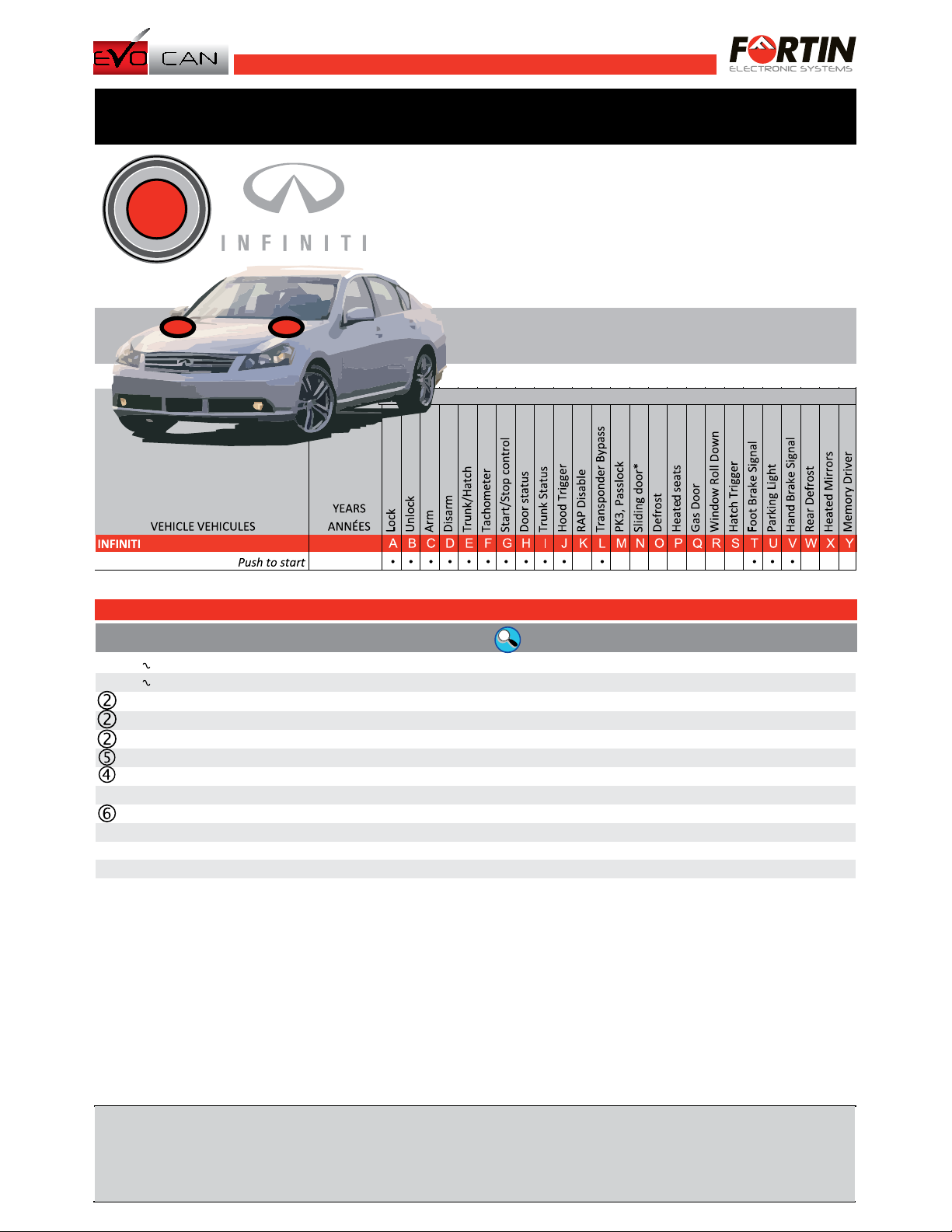
M35-M45 ADDENDUM - SUGGESTED WIRING CONFIGURATION
SCHÉMA DE BRANCHEMENT SUGGÉRÉ
M35 / M45 2006-2010
PUSH
START
Automatic Key Take Over:
Prise en charge du mode continue du véhicule:
When the door is opened after the vehicle has been remote-started and the SmartKey is in
proximity, the module will automatically trigger the Push-To-Start button and activate the vehicles ignition. The driver does
not need to manually press the Push-To-Start button. Lorsque la porte la porte
est ouverte après avoir démarré le véhicule et que la clé active
automatiquement l'ignition. Le conducteur n'a pas à appuyé sur le bouton .
à distance SmartKey est a proximité le module
Push-To-Start
Automatic Key Take Over:
Prise en charge du mode continue du véhicule:
When the door is opened after the vehicle has been remote-started and the SmartKey is in
proximity, the module will automatically trigger the Push-To-Start button and activate the vehicles ignition. The driver does
not need to manually press the Push-To-Start button. Lorsque la porte est
ouverte après avoir démarré le véhicule et que la clé active automatiquement
l'ignition. Le conducteur n'a pas à appuyé sur le bouton .
à distance SmartKey est a proximité le module
Push-To-Start
1
27
www.fortinbypass.com WEB UPDATE | MISE À JOUR INTERNET
WIRING COLOR | COULEUR DE FIL
DESCRIPTION COLOR | COULEUR LOCATION | EMPLACEMENT
POLARITY
POLARITÉ
CAN Bus (High) Blue OBDII connector (Twisted pair)
CAN Bus (Low) Pink OBDII connector (Twisted pair)
+
12 Volts 1 Blue Power Module behind Cluster 15
+
Ignition 1 Brown Power Module behind Cluster 18
+
Accessory 1 White Power Module behind Cluster 16
+
Starter 1 Black / Yellow Under hood, right side of battery
+
Parking Lights Red / Blue Dimmer switch
-
Emergency Brake Purple / Red Emergency Brake
+
Neutral Safety Switch Grey / Red Under hood, right side of battery
-
Trunk Release Orange BCM module 40 Pin Connector 30
-
Trunk Pin Light Blue BCM module 15 Pin Connector 2
-
Horn Brown / White Steering Column
Pin 6
Pin 14
Pin
Pin
Pin
Pin
Pin
Functional if equipped | Fonctionnelle si le véhicule en est équipé.
Rev. A - 20101110
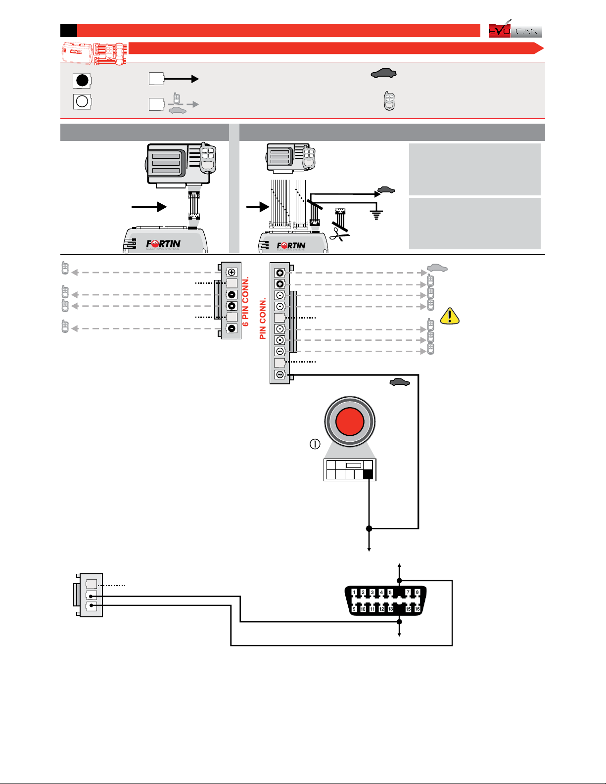
Cut off one plug of the 4 Pin
Data-Link connector
Connect the Red wire to +12V
Connect the Black wire to
Ground
1
2
3
Coupez l'extrémité du connecteur
4 pins Data-Link
Connectez le fil rouge au 12V
Connectez le fil noir à la masse
du véhicule.
1
2
3
Connect to vehicle
Branchement au véhicule
Connect to Remote-Starter/Alarm
Branchement au démarreur à
distance/Alarme
Input
Entrée
Output
Sortie Connection not required with Data-link
Branchement non requis avec Data-Link
Connection always required
Branchement toujours requis
INSTALLATION WITHOUT DATA-LINK
INSTALLATION SANS DATA-LINK
INSTALLATION WITH DATA-LINK
INSTALLATION AVEC DATA-LINK
Remote
Starter/Alarm with
the Fortin Data-link
protocol.
Démarreur à
distance/alarme
avec le protocole
Data-link Fortin 4 Pin
Remote
Starter/Alarm
Démarreur à
distance/alarme
Red | Rouge +12V
Black | Noir Ground
4 Pin
}
M35 / M45 CONTINUED | SUITE
ALL
EOALL
3
28 SUGGEST WIRING SCHEMATIC CONFIGURATION | SCHÉMA DE BRANCHEMENTS SUGGÉRÉS
3 PIN
CO
NN
.
Gray
Gray/Black
n.c.
Dk. Blue
Orange/Black
(-) While Running
Green
White Trunk Status
Door Status
Pink/Black
Pink
Hood Status
Tachometer
10
Foot Brake Status
Red/Blue
Lt. Blue
N.C.
Brown/WhiteHand Brake Status
Hood Pin:
Only if equipped.
Pin Capot:
Seulement si équipé.
Start/Stop Control
Push to Start
connector
Pin 4
Push Button
PUSH
START
CAN High: Blue
CAN 2 HIGH
CAN 2 LOW 6
14
CAN Low: Pink
N.C.
N.C.
N.C.
Parking Light
Purple/White
Purple
Unlock/Disarm
Lock/Arm
Ignition
Yellow
2This manual may change without notice. www.ifar.ca for latest version.

White
pin 16
Brown
Pin 18
141618
13
1517
Gray/Red
Neutral safety switch
30
86
85 87
87a
45
53 60
52
59
51
58
50
57
49
56
48
55
47
54
46
WARNING: Do not ground
this wire or you will
permanently damaged the
vehicle.
Pink/Blue
Copyright © 2007
FORTIN AUTO RADIO INC
Located at fuse box
right side of the battery.
Black/Yellow
Starter
(+) Accessory
(+) Ignition
(+) Parking Lights
(+) Brake
(+) Start
Under hood
(+) Accessoire
(+) Frein
(+) Lumière
de stationnement
Sous capot
Situé à la boîte à fusible
à droite de la batterie.
ATTENTION: Ne pas mettre
ce fil à la masse, cela
endommagerait le véhicule.
4
6
5
3
Red/Blue
1
29
www.fortinbypass.com WEB UPDATE | MISE À JOUR INTERNET
(+) 12 V
Blue
Pin 15
At Brake switch At dimmer switch
At power module behind cluster
Au gradateur de lumière
Au commutateur de frein
Au module d'alimentation derrière
l'odomètre
REMOTE STARTER
| DÉMARREUR À
DISTANCE
Copyright © 2010,
Fortin Auto Radio Inc
Copyright © 2010,
Fortin Auto Radio Inc Copyright © 2010,
Fortin Auto Radio Inc Copyright © 2010,
Fortin Auto Radio Inc
M35 / M45 CONTINUED | SUITE
3
Ce Guide peut faire l’objet de changement sans préavis. www.ifar.ca pour la récente version.

Démarrez à distance.
Entrez dans le véhicule avec la clé
intelligente (Intelli-Key)
et
refermez la porte côté conducteur.
Le bouton démarrage (Push-to-Start)
du véhicule se met à Ignition (ON)
automatiquement.
Vous êtes maintenant prêt à embrayer
et prendre la route.
Remote start the vehicle.
Enter the vehicle with the Intelli-Key
and
close the driver door.
The Push to Start button will turn ON
automatically.
The vehicle can now be put in to gear
and driven.
PROGRAMMING PROCEDURE | PROCÉDURE DE PROGRAMMATION
REMOTE STARTER FUNCTIONNALITY | FONCTIONNALITÉS DU DÉMARREUR À DISTANCE
Appuyez 2 fois sur le bouton démarrage
(Push to start) pour allumer l'ignition.
(Ne pas appuyer sur la pédale de frein)
Lorsque le DEL Bleu clignote
rapidement, appuyez une fois sur le
bouton démarrage (Push To Start) pour
éteindre l'ignition.
Le DEL bleu s'éteint pour indiquer que le
module est programmé.
ENGINE
START
STOP
ENGINE
START
STOP
x2
x1
ON
OFF
Press the Push-to-Start button twice to
turn on the ignition.
(Do not press the brake pedal)
Once the Blue LED starts to flash rapidly
press the Push-to-Start button once to
shut off the ignition.
The Blue LED will turn off to indicate the
module has been programmed.
4
5
Les DELS alternent entre un flash BLEU
et ROUGE, relâchez le bouton de
programmation quand la DEL est BLEU.
The LED will alternate between BLUE
and RED flashes. Release the
programming button when the LED is
BLUE.
If the LED is not solid BLUE disconnect the 4 Pin
connector (Data-Link) and go back to step 1
Press and hold the programming button
while inserting the 4 Pin (Data-Link)
connector into the EVO-CAN module.
Pressez le bouton de programmation en
insérant le connecteur 4 pins (Data-Link)
dans le EVO-CAN.
3
2
1
Si le DEL n'est pas BLEU débranchez le
connecteur 4 pins (Data-Link) et allez à l'étape 1.
LED | DEL
EVO-CAN
1
Insert the remaining connectors:
- 6 pin connector (White)
- 3 pin connector (White)
- 6 pin connector (Red)
- 2 pin connector (White)
* If required.
- 10 pin connector (White)
Insérez les connecteurs restants:
- connecteur 10 pins (Blanc).
- connecteur 3 pins (Blanc).
- connecteur 6 pins (Rouge).
- connecteur 2 pins (Blanc).
- connecteur 6 pins (Blanc).
* Si requis.
4This manual may change without notice. www.ifar.ca for latest version.
TECH SUPPORT
Tél: 514-255-HELP (4357)
1-877-336-7797
ADDENDUM GUIDE WEB UPDATE | MISE À JOUR INTERNET
www.fortinbypass.com
WARNING / TECH SUPPORT / MISE EN GARDE / SUPPORT TECHNIQUE
L'information de ce guide est fournie sur la base de représentation (telle quelle) sans aucune garantie de précision et
d'exactitude. Il est de la seule responsabilité de l'installateur de vérifier tous les fils et circuit avant défectuer les
connections. Seule une sonde logique ou un multimètre digital doivent être utilisés.
n'assume aucune responsabilité de l'exactitude de l'information fournie. L'installation (dans chaque
cas) est la responsabilité de l'installateur effectuant le travail. FORTIN SYSTÈMES ÉLECTRONIQUES n'assume aucune
responsabilité suite à l'installation, que celle-ci soit bonne ou mauvaise ou de n'importe autre type. Ni le manufacturier, ni le
distributeur ne se considèrent responsables des dommages causés ou ayant pu être causés, indirectement ou
directement, par ce module, excepté le remplacement de ce module en cas de défectuosité de fabrication. Ce module doit
être installé par un technicien qualifié. L'information fournie dans ce guide est une suggestion. Ce guide d'instruction peut
faire l’objet de changement sans préavis. Consultez le pour voir la plus récente version.
FORTIN SYSTÈMES
ÉLECTRONIQUES
www.fortinbypass.com
The information on this sheet is provided on an (as is) basis with no representation or warranty of accuracy whatsoever. It is
the sole responsibility of the installer to check and verify any circuit before connecting to it. Only a computer safe logic probe
or digital multimeter should be used. FORTIN ELECTRONIC SYSTEMS assumes absolutely no liability or responsibility
whatsoever pertaining to the accuracy or currency of the information supplied. The installation in every case is the sole
responsibility of the installer performing the work and FORTIN ELECTRONIC SYSTEMS assumes no liability or
responsibility whatsoever resulting from any type of installation, whether performed properly, improperly or any other way.
Neither the manufacturer or distributor of this module is responsible of damages of any kind indirectly or directly caused by
this module, except for the replacement of this module in case of manufacturing defects. This module must be installed by
qualified technician. The information supplied is a guide only. This instruction guide may change without notice. Visit
www.fortinbypass.com to get the latest version.
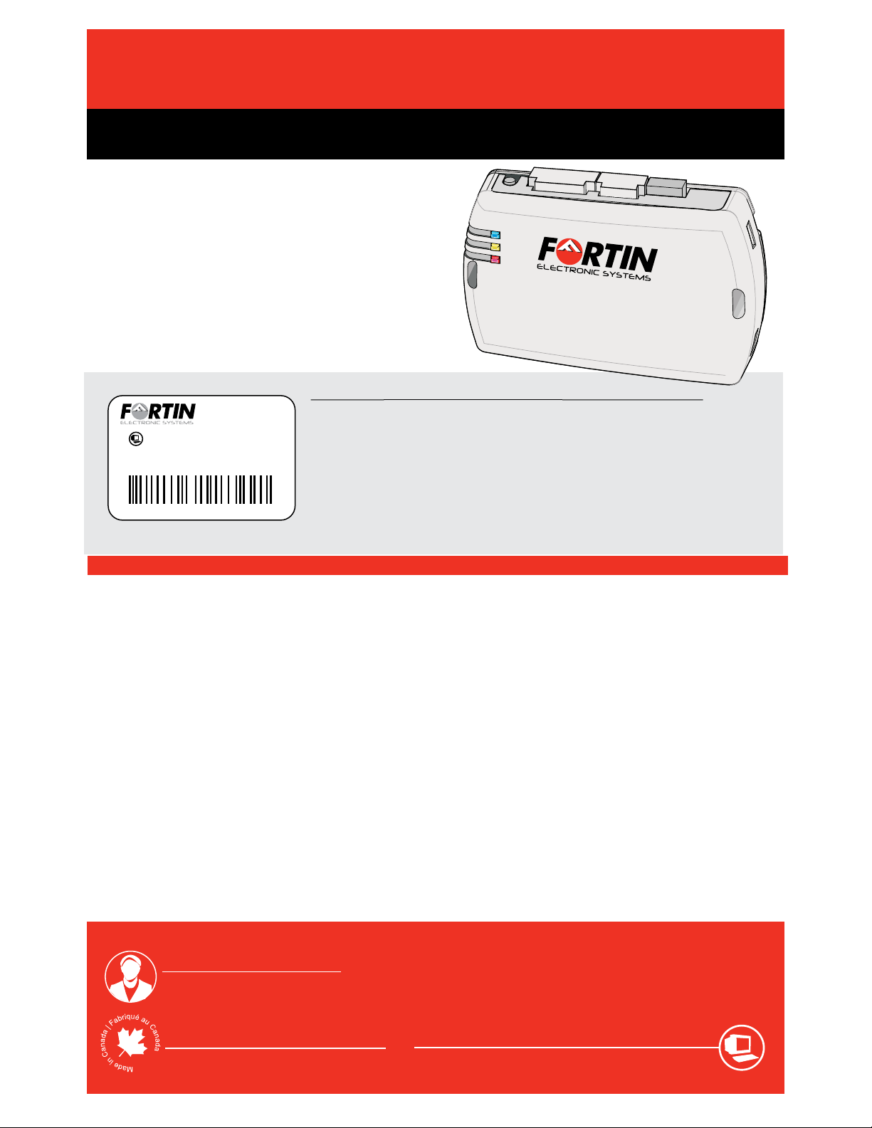
EVO-CAN
Copyright © 2006-2010, FORTIN AUTO RADIO INC ALL RIGHTS RESERVED PATENT PENDING
Service No : 000 102 04 2536
Date: xx-xx
INTERFACE MODULE
Made in Canada
PATENTS PENDING US: 2007-228827-A1
www.fortinbypass.com
HARDWARE VERSION
FIRMWARE VERSION
Module label | Étiquette sur le module
Updated firmware and installation guides are posted on our web
site on a regular basis. We recommend that you update this module to
the latest firmware and download the latest installation guide(s) prior
to the installation of this product.
Des mises à jour du Firmware (microprogramme) et des
guides d'installation sont mises en ligne régulièrement. Vérifiez
que vous avez bien la dernière version logiciel et le dernier guide
d'installation avant l'installation de ce produit.
EVO-CAN
Notice: Installation GuidesUpdated Firmware and
U.S. Patent No. 7,647,147
Canadian Patent No. 2,568,114
Brevet américain no. 7,647,147
Brevet canadien no. 2,568,114
This manual suits for next models
2
Other Fortin Electronic Systems Automobile Accessories manuals


Popular Automobile Accessories manuals by other brands

Lectron
Lectron CCS1 user manual

Rightline Gear
Rightline Gear 100B90 Setup guide

Safe Fleet
Safe Fleet Prime Design VCC TC21B Assembly instructions

Airlocker
Airlocker RD110 installation guide

Circontrol
Circontrol CCS CHA T2C63 instruction manual

Low Range Off-Road
Low Range Off-Road SEB-TD installation instructions


