Fortin Electronic Systems FSA-208 User manual

Rev.B 16/11/2010 Made in Canada

1 Installation Guide
TABLE OF CONTENTS
INTRODUCTION ..........................................................................................................................................................................................2
PART LIST..................................................................................................................................................................................................2
INSTALLATION POINTS TO REMEMBER..........................................................................................................................................................2
HARNESS DESCRIPTIONS ............................................................................................................................................................................3
6 PIN IGNITION HARNESS.................................................................................................................................................................................................3
18 PIN MAIN HARNESS .....................................................................................................................................................................................................5
MANUAL OR AUTOMATIC TRANSMISSION MODE............................................................................................................................................7
TRANSMITTER PROGRAMMING ....................................................................................................................................................................7
BEFORE PROGRAMMING...............................................................................................................................................................................................................7
TRANSMITTER PROGRAMMING PROCEDURE ............................................................................................................................................................................7
PROGRAMMING GUIDE................................................................................................................................................................................8
ADD REMOTE(OPTION #1)..............................................................................................................................................................................8
5TH RELAY(OPTION #2)........................................................................................................................................................................................8
CRANK TIME(OPTION #3)..............................................................................................................................................................................9
RUNTIME GAS (DIESEL)(OPTION #4)..........................................................................................................................................................9
ALARM OPTIONS(OPTION #5)....................................................................................................................................................................9
LOCK AND UNLOCK AFTER START(OPTION #6) ..................................................................................................................................9
IGNITION LOCK(OPTION #7)...........................................................................................................................................................................10
LOCK PULSE TIME(OPTION #8).................................................................................................................................................................10
PASSIVE OR ACTIVE ARMING(OPTION #9).............................................................................................................................................10
STARTER KILL (OPTION #10)........................................................................................................................................................................10
CONFIRMATION (OPTION #11)........................................................................................................................................................................10
CONFIRMATION SOUND (OPTION #12)....................................................................................................................................................10
CONFIRMATION TIME(OPTION #13)....................................................................................................................................................10
ALARM/STARTER(OPTION #14)..............................................................................................................................................................11
SMART ARMING(OPTION #15)..............................................................................................................................................................11
COLD STARTER TIMER(OPTION #16)....................................................................................................................................................11
DOMELIGHT DELAY(OPTION #17)..............................................................................................................................................................11
DIESEL MODE(OPTION #18)........................................................................................................................................................................11
TURBO MODE(OPTION #19)........................................................................................................................................................................11
TACH MODE(OPTION #20)..................................................................................................................................................................................11
START ATTEMPTS(OPTION #21)..............................................................................................................................................................11
SAFETY TRANSMITTER MODE(OPTION #22) .......................................................................................................................................11
RESET(OPTION #23)............................................................................................................................................................................................12
PUSH TO START(OPTION #24)........................................................................................................................................................................12
AUXILIARY 1(OPTION #25)........................................................................................................................................................................12
HYBRID(OPTION #26)............................................................................................................................................................................................12
AUXILIARY 2(OPTION #27)........................................................................................................................................................................12
NOT AVAILABLE(OPTION #28)........................................................................................................................................................................12
ALARM DURATION(OPTION #29)..............................................................................................................................................................12
VALET CODE(OPTION #30)........................................................................................................................................................................12
5TH RELAY(OPTION #31)..................................................................................................................................................................................13
GROUND OUT(OPTION #32)........................................................................................................................................................................13
NOT AVAILABLE(OPTION #33)........................................................................................................................................................................13
TRUNK PULSE(OPTION #34)........................................................................................................................................................................13
DISARM IGNITION(OPTION #35)..............................................................................................................................................................13
VALET MODE ACTIVATION/DEACTIVATION(OPTION #36) ........................................................................................................13
DOOR SECURITY SHUTDOWN(OPTION #37) .......................................................................................................................................13
REMOTE START / ALARM DIAGNOSTICS ......................................................................................................................................................14
REMOTE STARTER DIAGNOSTICS..............................................................................................................................................................................................14
ALARM DIAGNOSTICS.................................................................................................................................................................................................................14
CLOSING UP.............................................................................................................................................................................................15
LIABILITY.................................................................................................................................................................................................15

Installation Guide 2
INTRODUCTION
This guide contains all the information relevant and necessary for the installation of the
module. Most of the features of this product are explained in the User Guide. Therefore, if
detailed information regarding a feature of the product is needed, refer to the User Guide.
PART LIST
Please carefully read the installation guide before beginning the installation, especially the
harness descriptions and the programming options. It is very important that the
programming and the operation of the module are clearly understood, even with similar
installation experience in the past. There are many innovative features that may be
overlooked if this guide is not read thoroughly. Prior to the installation, make sure that all
the hardware components required to install the system are included in the box.
The following is a list of components included in the kit:
●1x Remote-Starter control unit
●1x or 2x Transmitters
●1x Antenna
●1x 6 pin primary ignition harness (AWG 14)
●1x 18 pin secondary harness (AWG 22)
●1x parts bag: a hood pin-switch, a connector and a warning label
●1x Valet switch (SPST)
●1x User guide
●1x Quick Installation guide
INDUSTRY CANADA USER NOTICE:
Operation is subject to the following two conditions: (1) this device may not cause
interference, and (2) this device must accept any interference, including interference
that may cause undesired operation of the device. To reduce potential radio interference
to other users, the antenna type and its gain should be so chosen that the equivalent
isotropically radiated power (EIRP) is not more than that required for successful
communication.
FCC – USER NOTICE:
The manufacturer is not responsible for any radio or TV interference caused by
unauthorized modifications to this equipment. Such modifications could void the user's
authority to operate the equipment.
INSTALLATION POINTS TO REMEMBER
•Make sure that vehicles equipped with an Automatic transmission can not start while in
any gear other than park. If the vehicle starts in gear, a Manual transmission Remote-
Starter must be installed.
•When installing a Manual transmission Remote-Starter on a vehicle with a Manual
transmission, always make sure that all doors will take the Remote-Starter out of Ready
Mode. If this is not the case switch the wire(s) so that the module can monitor all doors
(including the rear hatch).
•When installing a Manual transmission Remote-Starter on a vehicle with a Manual
transmission, ensure that the parking brake and all door switch contacts are working
properly.
•When working on a vehicle, never leave the keys inside the vehicle and always leave at
least one window open.
•If possible, remove the courtesy light fuse to prevent battery drain.
•Before beginning, inspect the vehicle for any body damage or electrical problems.
•Always solder and tape all connections.
•Keep the Antenna away from other types of antennas (GPS/OnStar).
•Never install the module or wiring where it could interfere with the mechanical operation
of the steering and pedals or obstruct service technicians.
•Always use a grommet when running wires into the engine compartment. Never run
wires near or against bare metal.

3 Installation Guide
•Do not disconnect the battery on vehicles equipped with air bags and anti-theft radios.
•Never ground the module to the vehicle’s steering column.
•Make sure that all the switches and controls operate properly.
•Verify that the vehicle starts and idles properly.
•Make sure that all safety equipment is installed: the Valet switch, Hood Pin switch and
warning label(s).
•Always make sure that all external relays and after-market products wired to the module
are properly fused and diode isolated.
•On vehicles equipped with daytime running lights, the installer may be unable to see
certain programming results since the daytime running lights never go out. (Note :
Listening carefully to the clicking of the relays within the module will indicate a selected
option. A test light on the positive park light output may also be used for a visual
indiciation)
•When wiring in parallel, make sure each connection is isolated with a diode in order to
avoid feedback and possible damage to the vehicle.
Examples :
1-Wiring both a clutch bypass and a transponder bypass module to the GROUND
OUT WHEN RUNNING wire: At the common connection point, where the GROUND
OUT WHEN RUNNING wire “splits” and connects to both devices, a diode should be
inserted on both wires to prevent feedback.
2-Multiple or separate door pin connections: When joining all Door Pins together to the
single input wire of the module, each of the door wires must be diode isolated to
prevent feedback.
•Note: The above examples reflect common situations where diodes are
use to isolate connections. Please note that there are numerous other
cases where diode isolation may be required.
HARNESS DESCRIPTIONS
When first connecting the system it is important to connect the primary 8 pin harness
(containing the ground wire) first, otherwise the internal components of the module could
be seriously damaged.
Be careful not to power up a module before it is properly grounded (Pin 4 of the 18 pins
connector). To avoid accidental damage, it is recommended to remove the fuses before the
installation, and to replace them once the installation is complete.
6 PIN IGNITION HARNESS
The two power wires are module inputs, while the remaining wires are outputs that
reproduce the electronic actions of the vehicle's ignition switch when Remote-Started.
These wires are usually connected at the ignition switch.
Do not modify the integrity of the vehicle by jumping any wires, this will compromise the
OEM electrical system.

Installation Guide 4
WIRE COLOUR FUNCTION DESCRIPTION
1 YELLOW
(+) Starter
Output
(30 A)
Connect to the vehicle's Starter wire. This
wire must have +12VDC only when the key
is at the CRANK position.
WARNING ! Some vehicle may have
more than one Starter wire. If necessary
use the 5th relay (pin 8) and an extra
relay(s) to power up each extra Starter
wire(s).
2 ORANGE
(+) Accessory
Output
(30 A)
Connect to the vehicle's Accessory wire
(blower motor). This wire must have
+12VDC when the key is at the RUN
postion, but not at the CRANK position.
WARNING ! Some vehicles may have
more than one Accessory wire. If
necessary use the 5th relay (pin 8) and an
extra relay(s) to power up each extra
Accessory wire(s).
3 PINK (+) Ignition
Output (30 A)
Connect to the vehicle's Ignition wire. This
wire must have +12VDC when the key is at
the RUN and CRANK position.
WARNING ! Some vehicles may have
more than one ignition wire. If necessary
use the 5th relay (pin 8) and an extra relay(s)
to power up any extra Ignition wire(s).
4 RED (+) 12 V Battery
Connect to the vehicle's constant +12VDC
power wire. Ensure that the vehicle’s power
wire is fused at more than 30A.
Note : Some modern vehicles do not have a
suitable +12VDC source at the Ignition
switch (the wires are too small to supply
enough current). In such cases, this wire
must be connected to a higher current
source (maybe even directly at the battery).
5RED (+) Battery 12V
Connect to the vehicle's constant +12VDC
power wire. Ensure that the vehicle’s power
wire is fused at more than 30A.
Note : Some modern vehicles do not have a
suitable +12VDC source at the Ignition
switch (the wires are too small to supply
enough current). In such cases, this wire
must be connected to a higher current
source (maybe even directly at the battery).
6 WHITE Ign. / Acc./ Start
Output
This wire is a high current output that can
either provide a 2nd Ignition, 2nd
Accessory or a 2nd Starter output. See the
programming guide (option 2) to program
the module for the desired output.

5 Installation Guide
18 PIN MAIN HARNESS
wire COLOUR FONCTION DESCRIPTION
1 BLACK (–) Chassis
Ground Input
This wire must be connected to bare,
unpainted, non-corroded metal (on the
vehicle chassis). It is preferable to use a
factory ground bolt rather than a self-tapping
screw. Screws loosen over time which cause
erratic behaviour.
2 GREY
(–) Hood Pin
Input
Zone 5
Connect to the Hood Pin safety switch.
Note: This input should be at ground
whenever the hood is opened to prevent
Remote-Starting.
IMPORTANT! Mandatory on all vehicles.
3 BROWN/
YELLOW
(–) Door Pin
Input
Zone 3
This zone should be used in a vehicle equipped
with a negative door pin circuit. This zone
triggers the alarm.
WARNING ! Ensure this wire is grounded
whenever any door is opened. Only
connecting the drivers door is not sufficient.
4 DK GREEN
(–) Trunk Pin
Input
Zone 6
This zone triggers the alarm.
5 YELLOW
(–) Starter Kill
/Anti-Grind
Output
This wire provides a starter kill signal with
PASSIVE and ACTIVE arming. The wire is
meant to immobilize the vehicle whenever the
Alarm is armed, and provide anti-grind
whenever Remote-Started by providing a
constant negative output (400mA) when the
Alarm is armed or Remote-Started. This wire
is meant to be connected to an external relay.
(See Quick Installation Guide).

Installation Guide 6
wire COLOUR FONCTION DESCRIPTION
6 WHITE/
GREEN
(–) Unlock
Output
This output provides a negative unlock pulse
(400mA). This pulse is programmable for
either a single 1 second, single 4 second, or
double 1 second pulse(s).
7 YELLOW/
GREEN
(–) Disarm
Output
This ouput provides a single negative disarm
pulse (400mA) for 1 second whenever the
doors are unlocked. This signal is sent 10ms
after the unlock signal.
Note : A single disarm pulse is also provided
before Remote-Start.
8 PINK/
BLACK
(–) Ignition
Output
Connect to either the negative Ignition wire of
the vehicle, or to an external relay (400mA).
The vehicle’s Ignition wire will ground when
the key is in either the RUN or CRANK
position.
Warning ! Some vehicles may have more
than one Ignition wire.
9 BROWN
(+) Park Light
Output
Connect to the vehicle's parking light wire
(15A). This wire has +12VDC when the
parking light switch is turned on.
Note : Ensure the voltage remains at
+12VDC when the dimmer control switch is
adjusted. If the voltage fluctuates, find another
parking light wire.
Note :
There is also a negative park light
output (24pin connector, Tan/Black),
however only one should be connected.
10 WHITE (+) Brake
Switch Input
This input should be connected to an external
sensor that will provide a signal to trigger the
alarm. This input is ignored for 15 seconds
after arming and for the entire duration of
remote-start.
This input is used with the Neutral Safety
Switch.
11 WHITE/
BLACK
(–) Trunk
Output
This output (400mA) should be connected to
either the trunk release switch, or control a
high current relay that powers the
trunk/hatch solonoid.
12 ORANGE
(+) Door Pin
Input
Zone 3
This zone should be used in a vehicle equipped
whit a positive door pin circuit. This zone
triggers the alarm.
WARNING ! Ensure opening any door will
power this wire. Only connecting the drivers
door is not sufficient.
13 DK. BLUE
(–) Ground Out
When Running
Output
This output (400mA) provides a constant
ground when the engine is Remote-Started. It
is activated 1 second before Remote-Start
and deactivated 1 second after shut-down.
CAUTION : If this wire is used to control
several relays and/or modules ensure each
output is diode isolated to prevent feedback
which can damage the vehicle.
14 WHITE/
RED
(–) Lock
Output
This output (400mA) provides a single
negative LOCK pulse for 1second.
7 Installation Guide
wire COLOUR FONCTION DESCRIPTION
15 DARK
BLUE
(–) Ground Out
When Running
Output
This output (400mA) provides a constant
ground when the engine is Remote-Started. It
is activated 1 second before Remote-Start
and deactivated 1 second after shut-down.
CAUTION : If this wire is used to control
several relays and/or modules ensure each
output is diode isolated to prevent feedback
which can damage the vehicle.
16 YELLOW/
RED
(–) Arming
Output
This ouput (400mA) provides a single
negative ARM pulse for 1 second whenever
the doors are locked. It is enabled 500ms
before, and disabled 250ms after the LOCK
pulse. Note : A single ARM pulse is also
generated after Remote-Start shut-down.
17 BROWN/
WHITE
(–) Park Light
Output
Connect to the vehicle's parking light wire.
This wire will ground when the parking light
switch is turned on.
Note :
There is also a positive park light
output (8pin connector, Brown), however only
one should be connected.
18 LIGHT
BLUE
(A.C.)
Tachometer
Input
Connect to a tachometer source at either the
ignition coil, an injector, camshaft sensor,
crankshaft sensor, or at the ECM (Engine
Control Module). This wire allows the module
to measure the engines RPM.
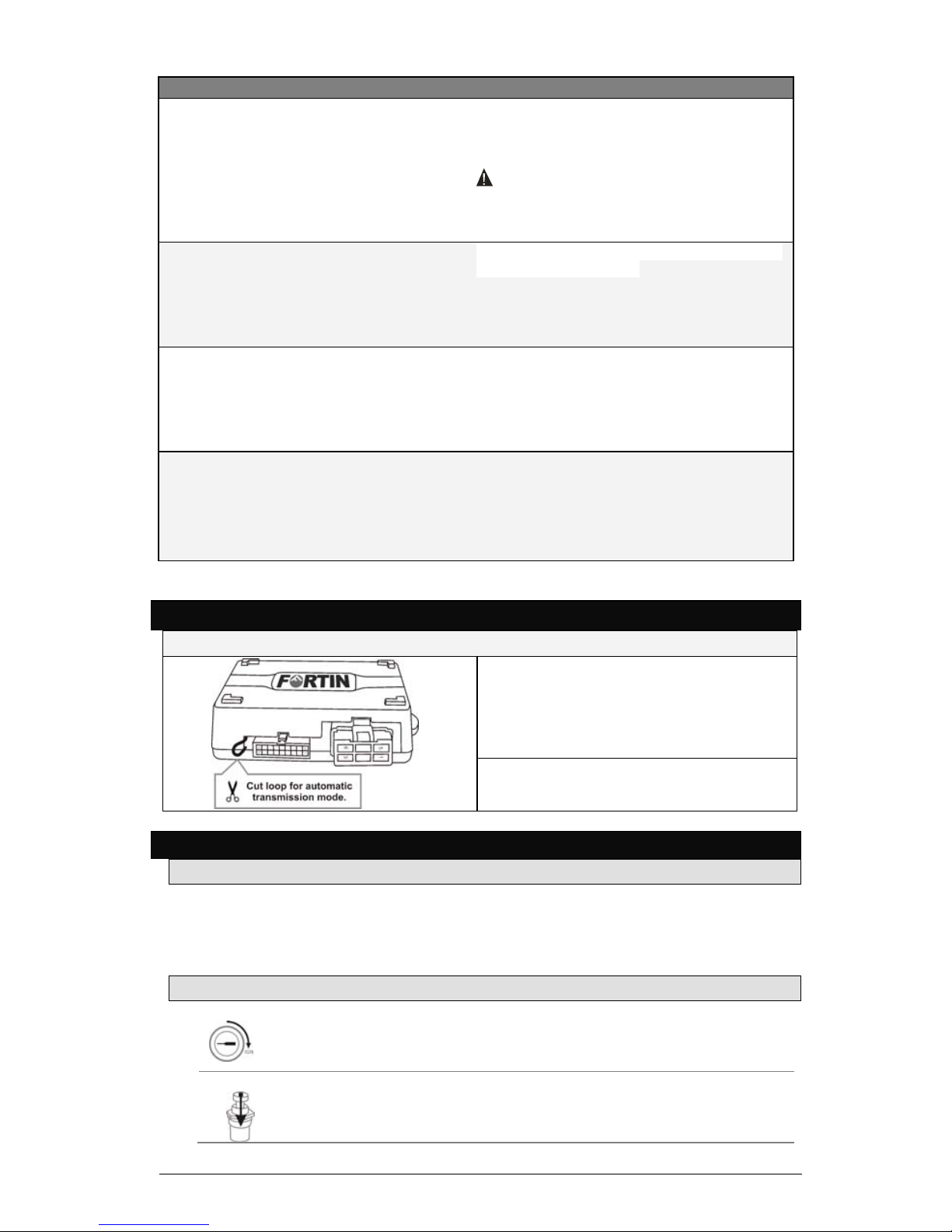
MANUAL OR AUTOMATIC TRANSMISSION MODE
W
ARNING !
MANUAL MODE :
DO NOT cut the loop for a Manual
transmission vehicle, this will void all
guarantees and warranties.
AUTOMATIC MODE :
Cut the loop for an Automatic transmission
vehicle.
TRANSMITTER PROGRAMMING
BEFORE PROGRAMMING
The Transmitters included with the module are NOT pre-programmed: they each need to
be manually programmed after installation is complete. The Remote-Starter/Alarm can
learn up to a maximum of 4 Transmitters. Once a 5th Transmitter is programmed the
1st transmitter is erased (FIFO).
TRANSMITTER PROGRAMMING PROCEDURE
Step 1
Disarm alarm, disable valet mode.
Turn the ignition ON
Step 2
Press and hold the Valet Switch (5 seconds) until the LED
flashes, then release the Valet Switch.

Installation Guide 8
Step 3
Press and release the Valet Switch once.
The park-lights will flash to confirm.
Step 4
Press and release the brake pedal once.
Step 5
On each Transmitter press the LOCK button once (maximum
4 transmitters), the park-lights will flash to confirm.
Step 6
Press and release the brake pedal once.
Step 7
Turn the Ignition off.
PROGRAMMING PROCEDURE
Step 1
Disarm, alarm, disable valet mode.
Turn the Ignition on.
Step 2
Press and hold the valet-switch until the LED flashes, then
release.
Step 3
Press and release the valet-switch 1-29 times for the
desired channel. The park-lights will flash and the
horn/siren will chirp once to confirm.
Step 4
Press and release the brake-pedal once.
Step 5
Press the lock (1), unlock (2), trunk (3) or start (4) button
on either programmed remote to select the mode, the park-
lights flashes 1 to 6 time to confirm.
Step 6
Turn the Ignition off to exit programming.
The parklights will flash 4 times.
PROGRAMMING GUIDE
See Quick Install Guide for the latest version of PROGRAM GUIDE.
ADD REMOTE (Option #1)
Program a new transmitter.
MODE 1 (Button 1) Program driver 1
MODE 2 (Button 2) Program driver 2 (Data-Link only)
MODE 3 (Button 3) Multivehicle programming
5TH RELAY (Option #2)
Relay configuration. Button 4: For Toyota. Button 1 and 2: For Dodge Ram.
MODE 1 (Button 1) 2nd Ignition
MODE 2 (Button 2) 2nd Accessory
MODE 3 (Button 3) 2nd Start

9 Installation Guide
MODE 4 (Button 4) Pink : Ignition
Orange : 2nd Ignition
White : Start
Yellow : 2nd Start
Brown : Parking (+)
MODE 5 (Button 1 and 2) Pink : Ignition
White : 2nd Ignition
Orange : Accessory
Brown : 2nd Accessory
Yellow : Start
Brown/White : Parking (-)
MODE 6 (Button 3 and 4) Pink : Ignition
White : Starter
Orange : Accessory
Brown : 2nd Ignition
Yellow : 2nd Starter
Brown/White : Parking (-)
CRANK TIME (Option #3)
This programming option adjusts the length of crank time for the Remote-Starter. If the vehicle over-
cranks or under-crank, the crank time can be adjusted. This works with both tachometer wired mode,
and tachless mode.
When reprogramming option 3 (Crank time)
*-Each press of button 1 (LOCK) will gradually increase the length of crank time.
(Required when the vehicle under-cranks)
**-Each press of buttons 3 + 4 (TRUNK, START) simultaneously will gradually decrease the length of
crank time. (Required when the vehicle over-cranks)
Length of time the starter will crank.
MODE 1 (Button 1) Increase
MODE 2 (Button 2) +++++
MODE 3 (Button 3) ++++
MODE 4 (Button 4) +++
MODE 5 (Button 1 and 2) ++
MODE 6 (Button 3 and 4) Decrease
RUNTIME GAS (DIESEL) (Option #4)
The Remote-Starter runtime in minutes. (x2) in diesel mode. (See option #18)
MODE 1 (Button 1) 15 (30)
MODE 2 (Button 2) 7 (14)
MODE 3 (Button 3) 3 (6)
ALARM OPTIONS (Option #5)
Simultanously change functions #7, #9, #14 and #15.
MODE 1 (Button 1) Disable all
MODE 2 (Button 2) Enable all
LOCK AND UNLOCK AFTER START (Option #6)
This programming option allows the Remote-Starter to control the OEM alarm on some vehicles by
sending a unlock pulse before Remote-Start and an lock pulse(s) after shut-down.
By enabling this option (Mode 2), the system will unlock the door’s before Remote-Starting, and re-LOCK
the door’s after Remote-Start shut-down only if the key is not in the ignition (ON/RUN) position.
If only the LOCK option is enabled (Mode 3), the doors will not UNLOCK before Remote-Start, but will
LOCK after shut-down only if the key is not in the ignition (ON/RUN) position.
Note: The majority of OEM alarm systems will not permit the Alarm to ARM when the engine is running
(ON/RUN).
UNLOCK before Remote-Start, LOCK after Remote-Start, LOCK after shut-down.
MODE 1 (Button 1) Disable
MODE 2 (Button 2) Enable
MODE 3 (Button 3) Lock Only
MODE 4 (Button 4) Lock/Unlock after shut down
MODE 5 (Button 1 and 2) Verrouille 10 secondes après l’arrêt du démarreur
à distance

Installation Guide 10
IGNITION LOCK (Option #7)
When enabled, a LOCK pulse is sent when the key is at the ON/RUN position and the brake pedal is
pressed, and a subsequent UNLOCK pulse is sent when the key is turned to the OFF position.
Automatically LOCK/UNLOCK the doors whenever the key is used to start/shut-down the vehicle.
MODE 1 (Button 1) Disable
MODE 2 (Button 2) Enable
MODE 3 (Button 3) Unlock Only
LOCK PULSE TIME (Option #8)
The LOCK and UNLOCK pulse time can be configured for:
●1 x 0.25s, 0.75s, 1.25s or 2.5s LOCK pulse and 1x 0.25s, 0.75s, 1.25s or 2.5s ms UNLOCK
pulse.
●1 x 4 second LOCK and 1 x 4 second UNLOCK pulse for vacuum door locks.
●1 x 250ms LOCK pulse, 2 x 250ms UNLOCK pulse for vehicles requiring a double-UNLOCK to
DISARM.
(250ms = ¼ second.)
MODE 1 (Button 1) Single 0.25 sec
MODE 2 (Button 2) Double 0.25 sec
MODE 3 (Button 3) Single 4.0 sec
MODE 4 (Button 4) Single 2.5 sec
MODE 5 (Button 1 and 2) Single 1.5 sec
MODE 6 (Button 3 and 4) Single 0.75 sec
PASSIVE OR ACTIVE ARMING (Option #9)
Once the key is turned OFF, and all the doors are closed the Alarm can automatically ARM itself in 1 of 2
ways:
●ACTIVE MODE: the Alarm (and starter-kill) will not ARM automatically. Only pressing the
transmitters’s LOCK button will ARM, the UNLOCK button will DISARM the Alarm.
●PASSIVE MODE: (default) the Alarm (and starter-kill) will ARM automatically if not manually armed
within 30 seconds. Pressing the transmitter’s UNLOCK button will DISARM the Alarm.
MODE 1
(Button 1)
Active Press LOCK to activate the Alarm or the starter-
kill.
MODE 2
(Button 2)
Passive with lock
disable
If the engine is OFF and the doors are closed, the
Alarm will reactivate in 30 seconds.
Disable alarm option: for mode 2,when the Ignition is
OFF the starter-kill will activate in 30 seconds.
MODE 3
(Button 3)
Passive with Lock
enabled
When the Ignition is OFF, and the doors are closed,
the Alarm will reactivate and LOCK.
STARTER KILL (Option #10)
Starter-kill: (-) while armed, Anti-grind: (-) while running.
MODE 1 (Button 1) Starter-kill & anti-grind
MODE 2 (Button 2) Anti-grind
MODE 3 (Button 3) Relay normally open
CONFIRMATION (Option #11)
Audible Alarm confirmation & LED options.
MODE 1 (Button 1) Silent
MODE 2 (Button 2) Always chirp
MODE 3 (Button 3) LED off
MODE 4 (Button 4) LED off at ignition
CONFIRMATION SOUND (Option #12)
Audible Siren and/or Horn confirmation.
MODE 1 (Button 1) Horn
CONFIRMATION TIME (Option #13)
Horn duration.
MODE 1 (Button 1) Long
MODE 2 (Button 2) Short

11 Installation Guide
ALARM/STARTER (Option #14)
Alarm/Starter features enabled/disabled.
MODE 1 (Button 1) Alarm OFF - Starter ON
MODE 2 (Button 2) Alarm ON - Starter ON
MODE 3 (Button 3) Alarm ON - Starter OFF
SMART ARMING (Option #15)
Once the Alarm is DISARMED the doors will LOCK and the Alarm will REARM if no doors are opened for
30 seconds. Opening a door within 30 seconds will cancel this feature.
Note: The door triggers must be connected to the Remote-Starter to activate this function.
Automatically LOCK if door(s) not opened within 30 seconds.
MODE 1 (Button 1) Disable
MODE 2 (Button 2) Enable
MODE 3 (Button 3) Lock when starter kill activates
MODE 4 (Button 4) Only 1 re-arm pulse. No subsequent re-arm pulses
when system is already armed.
COLD STARTER TIMER (Option #16)
Cold Start Remote-Starter delay. Maximum 24 hour cycle.
MODE 1 (Button 1) 3 hours
MODE 2 (Button 2) 1.5 hours
MODE 3 (Button 3) 3 hours / 5 minutes
MODE 4 (Button 4) 1.5 hours / 5 minutes
DOMELIGHT DELAY (Option #17)
Ignore door trigger (dome light) when arming or Remote-Starting.
MODE 1 (Button 1) Disable
MODE 2 (Button 2) Enable
DIESEL MODE (Option #18)
Delay between Ignition power up and Starter (crank).
MODE 1 (Button 1) Disable
MODE 2 (Button 2) Enable (20)
MODE 3 (Button 3) Enable (10)
TURBO MODE (Option #19)
This function should be used on vehicles equipped with a Turbo..
Automatic Remote-Start takeover when park brake applied. (2 minute runtime)
MODE 1 (Button 1) Disable
MODE 2 (Button 2) Enable 2 min
MODE 3 (Button 3) Enable 4 min
TACH MODE (Option #20)
If it is difficult to locate a tachometer signal in the vehicle this will allow the Remote-Starter to detect the
engine’s RPM without requiring a tachometer wire.
Remote-Starter does not require wired tachometer to determine cranking threshold or tach idle mode
programming
MODE 1 (Button 1) Supervision only
MODE 2 (Button 2) Voltage sensing
MODE 4 (Button 4) Start (crank) 8 sec
MODE 5 (Button 1 and 2) Start (crank) 8 sec + supervision by Data-Link Tach
MODE 6 (Button 3 and 4) Supervision and crank by Data-Link Tach
START ATTEMPTS (Option #21)
In extreme cold weather the Remote-Starter may fail to start the vehicle on its first attempt. This
programming option will adjust the number of times (1,2 or 3) that the Remote-Starter will attempt to
start the vehicle before giving up.
The number of Remote-Start attempts.
MODE 1 (Button 1) 2
MODE 2 (Button 2) 1
MODE 3 (Button 3) 3
SAFETY TRANSMITTER MODE (Option #22)
This programming option is a child safety feature that requires the Transmitter's TRUNK and START
button(s) to be pressed for at least 3 seconds.

Installation Guide 12
Seconds required to depress button.
MODE 1 (Button 1) Disable (1 second)
MODE 2 (Button 2) Enable (3 seconds)
RESET (Option #23)
This programming option does a master reset on all programming options (1-29) by setting them to
their default value (Mode 1). This does not remove any Transmitter’s from memory.
RESET ALL options to default (Mode 1).
MODE 1 (Button 1) RESET
PUSH TO START (Option #24)
Invert the Ignition and Brake wire to adapt the remote-starter to support a push-to-start ignition system.
MODE 1 (Button 1) Disable
MODE 2 (Button 2) Enable
MODE 3 (Button 3) Enable Security: Turn OFF the engine when the door
is open
MODE 4 (Button 4) Enable Security: Turn OFF the engine when the foot-
brake is pressed
AUXILIARY 1 (Option #25)
Auxiliary 1 channel Configuration.
MODE 1 (Button 1) Slidding doors (DATA-LINK ONLY)
HYBRID (Option #26)
Function for hybrid vehicles.
MODE 1 (Button 1) Disable
MODE 2 (Button 2) Enable
AUXILIARY 2 (Option #27)
Auxiliary 2 channel Configuration.
MODE 1 (Button 1) Slidding doors (DATA-LINK ONLY)
NOT AVAILABLE (Option #28)
ALARM DURATION (Option #29)
Duration of horn/siren when an alarm is triggered.
MODE 1 (Button 1) 30 seconds
MODE 2 (Button 2) 60 seconds
MODE 3 (Button 3) 120 seconds
VALET CODE (Option #30)
The Valet Mode be enabled to prevent an accidental Remote-Start. The alarm system is not
active (including Starter Kill) when the system is in Valet Mode. However you are still able to
lock and unlock the doors, and release the rear hatch/trunk.
VALET CODING DISBALED (DEFAULT):
1. Insert the key and turn it to the ignition (ON/RUN) position. The vehicle does not need
to be started.
2. Within 10 seconds press (1 second) and release the Valet switch 3 times.
3. Valet mode enabled: The LED is ON. Valet mode disabled: The LED is OFF
VALET CODING ENABLED (ENABLE):
1. Insert the key and turn it to the ignition (ON/RUN) position. The vehicle does not need
to be started.
2. Within 10 seconds press and release the valet button 3 to 7 times (X = valet code) for
1 second. If your valet code is 7 then press and release the valet button 7 times.
3. Press and hold the valet button once for 3 seconds to finish the sequence.
4. Valet mode enabled:The LED is ON. Valet mode disabled: The LED is OFF
MODE 1 (Button 1) Default See User Guide p.6
MODE 2 (Button 2) Valet code: 3
MODE 3 (Button 3) Valet code: 4

13 Installation Guide
MODE 4 (Button 4) Valet code: 5
MODE 5 (Button 5) Valet code: 6
MODE 6 (Button 6) Valet code: 7
5TH RELAY (Option #31)
5th relay configuration.
MODE 1 (Button 1) Disable
MODE 2 (Button 2) Enable Latch after start
MODE 3 (Button 3) Enable Trunk Output
GROUND OUT (Option #32)
When the remote starter turn off, it is possible to program the Ground Out output to stay activated 1 or
3 seconds after the vehicle shut down.
MODE 1 (Button 1) Active 1 second after shut-down
MODE 2 (Button 2) Active 3 seconds after shut-down
NOT AVAILABLE (Option #33)
TRUNK PULSE (Option #34)
Trunk output configuration, 0.5 second or 2.5 second Ground pulse and ability to unlock doors before
trunk pulse.
MODE 1 (Button 1) 0.5s
MODE 2 (Button 2) 2.5s
MODE 3 (Button 3) Unlock before
DISARM IGNITION (Option #35)
If enabled the remote starter will simultaneously activate the ignition ON and GWR (Ground Out While
Running) output for 0.5s to disarm the vehicles OEM alarm using the immobilizer bypass.
MODE 1 (Button 1) Disable
MODE 2 (Button 2) Disarm with Ignition and GWR
VALET MODE ACTIVATION/DEACTIVATION (Option #36)
Valet mode activation using the remote and/or the valet switch.
MODE 1 (Button 1) Valet switch or LOCK+UNLOCK
MODE 2 (Button 2) Valet switch or AUX » LOCK+UNLOCK
MODE 3 (Button 3) Valet switch only
DOOR SECURITY SHUTDOWN (Option #37)
Door-pin observation for protection on vehicles with proximity keys.
MODE 1 (Button 1) Disable
MODE 2 (Button 2) Enable, shuts down the engine if any door is opened
before UNLOCK is pressed.

Installation Guide 14
REMOTE START / ALARM DIAGNOSTICS
The user is able to identify the cause of a Remote-Starter failure (after shut-down), or
determine the zone which triggered the Alarm (after UNLOCK) through the number of park
light flashes.
REMOTE STARTER DIAGNOSTICS
Parking Light flashes (before starting) :
3x Ready Mode disabled
4x Valet Mode activated (The LED is on)
5x Hood open
Parking Light flashes (after starting) :
1x Normal stop (Brake, Park Brake)
3x Runtime expired or shut down by Transmitter
4x No tachometer signal
5x Hood open
6x Over crank threshold (8 seconds)
ALARM DIAGNOSTICS
Parking Light flashes (after disarm) :
3x Door open – zone 3
4x Shock sensor – zone 4
5x Hood open – zone 5
6x Trunk open – zone 6
7x Auxiliary IN– zone 7
8x Tilt Sensor – zone 8
9x Ignition – zone 9
INSTALLATION VERIFICATION
Before finishing the installation and reassembling the vehicle, it is recommended that the
Remote-Starter/Alarm is verified to be operating properly. Before testing, ensure all
connections are soldered, isolated, and the Remote-Starter/Alarm is plugged in. Remote-
Start the vehicle and listen to the starter (crank) threshold. If the Starter crank time is to
long or to short, adjust the sensitivity of the Crank Threshold (option #3).
•Hood Pin switch : WARNING When the Remote-Starter is running, open the
hood. The Remote-Starter should shut down immediately.
The installation of the hood pin switch is mandatory.
•Brake pedal switch : When the Remote-Starter is running, press the brake pedal. The
Remote-Starter should shut down immediately.
•Vehicle Idle Mode (Manual Transmission) : Ensure the Remote-Starter properly
enters and exits Idle Mode.
•Door pin switch(es) (Manual Transmission) : When the Remote-Starter is in Ready
Mode, ensure Ready Mode is immediately cancelled when any doors (including rear
hatch) are opened.
•Parking brake (Manual Transmission) : When the Remote-Starter is in Ready Mode,
ensure that Ready Mode is immediately cancelled when the parking brake is released.
•OEM alarm control : Ensure the module will ARM and DISARM the vehicle's OEM
alarm (if equipped) whenever the doors are LOCKED, UNLOCKED, and when the
Remote-Starter is either Remote-Started or shut-down.
•Door LOCKS and TRUNK : Ensure all of the doors respond to all Transmitters by
LOCKING and UNLOCKING the doors, and releasing the TRUNK.
•Starter Kill relay : Sit inside the vehicle with all the doors closed, ARM the system,
and then try to start the engine with the key. The Starter should not crank, and the
engine should not start.

15 Installation Guide
•Valet mode : Ensure the Remote-Starter/Alarm is able to enter and exit Valet Mode.
When the Remote-Starter/Alarm is in Valet Mode, pressing the LOCK button will
LOCK the doors without activating the starter kill. (Refer to the User Guide for further
information on Valet Mode)
•Alarm : ARM the Alarm, and ensure that opening any door, the hood, the trunk, and
the Shock Sensor will all trigger the Alarm.
CLOSING UP
Use tie-wraps and screws to properly secure the Remote-Starter/Alarm and to keep all
wiring away from any moving parts such as the parking brake, steering column, and foot
pedals. Mount all switches in an accessible location where they do not risk getting
accidentally kicked or hit.
Ensure all warning labels are applied on clean, visible location under the hood. Do not stick
them to the engine block or exhaust manifold.
Most warranty claims are the result of the user (driver) misunderstands how the Remote-
Starter/Alarm works and performs. Take the time to properly explain all of the installed
features and functions to the customer(s) before they leave the premises.
LIABILITY
Neither the manufacturer or distributor of this module are responsible for damages of any
kind indirectly or directly caused by this Remote-Starter/Alarm or any of its pieces, except
for the replacement of the module in case of manufacturing defects. All pieces must be
installed by qualified technician. This Instruction Guide may change without notice. Visit
http://ifar.ca/files/FSA208/ for the latest version.

Rev.B 16/11/2010 Fabriqué au Canada

1Guide d’installation
TABLE DES MATIÈRES
INTRODUCTION ..........................................................................................................................................................................................2
INCLUS DANS LA TROUSSE..........................................................................................................................................................................2
À RETENIR LORS DE L’INSTALLATION ............................................................................................................................................................2
DESCRIPTION DU CABLAGE..........................................................................................................................................................................4
CONNECTEUR D’ALLUMAGE À 6 BROCHES................................................................................................................................................................4
CONNECTEUR PRINCIPAL À 18 BROCHES..................................................................................................................................................................5
SELECTION DU MODE AUTOMATIQUE OU MANUEL .......................................................................................................................................... 7
PROGRAMMATION DE LA TÉLÉCOMMANDE.................................................................................................................................................... 8
AVANT DE PROGRAMMER ..................................................................................................................................................................................................8
PROGRAMMATION DES TÉLÉCOMMANDES ...............................................................................................................................................................8
PROGRAMMATION DES OPTIONS PAR LES TÉLÉCOMMANDES........................................................................................................................8
TABLEAUX DE PROGRAMMATION .................................................................................................................................................................9
AJOUTER UNE TELECOMMANDE (OPTION #1) .......................................................................................................................9
5IEME RELAIS(OPTION #2)................................................................................................................................................................................9
SEUIL DE DEMARRAGE(OPTION #3)....................................................................................................................................................9
DUREE D’EXECUTION GAZ (DIESEL)(OPTION #4)..................................................................................................................9
OPTIONS D’ALARME (OPTION #5)...........................................................................................................................................................9
VERROUILLAGE ET DÉVERROUILLAGE AU DEMARRAGE(OPTION #6).......................................................9
VERROUILLAGE DES PORTIÈRES A L’ALLUMAGE(OPTION #7) ........................................................................10
DUREE DE L’IMPULSION DE VERROUILLAGE (OPTION #8)....................................................................................10
ARMEMENT PASSIF OU ACTIF(OPTION #9)..............................................................................................................................10
ANTI-DEMARREUR(OPTION #10)......................................................................................................................................................10
CONFIRMATION(OPTION #11)................................................................................................................................................................11
MEDIUM DE CONFIRMATION(OPTION #12)..............................................................................................................................11
TEMPS DE CONFIRMATION(OPTION #13)...................................................................................................................................11
ALARME / STARTER(OPTION #14)......................................................................................................................................................11
VERROUILLAGE INTELLIGENT(OPTION #15).............................................................................................................................11
DEMARRAGE PERIODIQUE(OPTION #16) .....................................................................................................................................11
RETARDEMENT DU PLAFONNIER(OPTION #17)..................................................................................................................11
MODE DIESEL(OPTION #18)..........................................................................................................................................................................11
MODE TURBO(OPTION #19)................................................................................................................................................................11
SANS TACH(OPTION #20)..........................................................................................................................................................................11
TENTATIVE DE DEMARRAGE(OPTION #21)................................................................................................................................12
MODE TÉLÉCOMMANDE SECURITAIRE(OPTION #22).................................................................................................12
REINITIALISATION(OPTION #23).....................................................................................................................................................12
PUSH TO START(OPTION #24)................................................................................................................................................................12
AUXILIAIRE 1 (OPTION #25)..........................................................................................................................................................................12
HYBRIDE (OPTION #26)....................................................................................................................................................................................12
AUXILIAIRE 2 (OPTION #27)..........................................................................................................................................................................12
NON DISPONIBLE(OPTION #28)......................................................................................................................................................12
DUREE DE L’ALARME (OPTION #29)...................................................................................................................................................12
CODE VALET(OPTION #30)..........................................................................................................................................................................13
5IEME RELAIS(OPTION #31)................................................................................................................................................................13
GROUND OUT(OPTION #32)..........................................................................................................................................................................13
NON DISPONIBLE(OPTION #33)......................................................................................................................................................13
PULSATION VALISE(OPTION #34)......................................................................................................................................................13
IGNITION DESARMEMENT(OPTION #35)......................................................................................................................................13
ACTIVATION / DESACTIVATION DU MODE VALET(OPTION #36)....................................................................14
ARRET DOUBLE SECURITE(OPTION #37)......................................................................................................................................14
RELEVE DES EVENEMENTS ........................................................................................................................................................................14
DIAGNOSTIC DE L’ALARME ........................................................................................................................................................................................................14
VERIFICATIONS ........................................................................................................................................................................................14
POUR TERMINER ......................................................................................................................................................................................15
INFORMATION.......................................................................................................................................................................................... 15

Guide d’installation 2
INTRODUCTION
Ce guide d’installation contient tous les renseignements pertinents et nécessaires à
l’installation du système. La plupart des caractéristiques du produit sont décrites dans le
guide de l’utilisateur. Si vous avez besoin d’explications détaillées sur une caractéristique du
produit, nous vous recommandons de consulter le guide de l’utilisateur.
INCLUS DANS LA TROUSSE
Avant de commencer l’installation, veuillez lire attentivement le guide d’installation, en
particulier la section description du câblage et les options de programmation. Il est très
important que vous vous familiarisiez avec la programmation et le maniement du système,
même si vous avez déjà installé un système analogue par le passé. Ce produit possède de
nombreuses caractéristiques innovatrices dont vous risquez de ne pas tirer profit si vous
ne lisez pas le guide. Avant de procéder à l’installation, assurez-vous que toutes les pièces
requises pour l’installation sont dans la boîte.
Voici une liste des pièces comprises dans la trousse :
●1 Unité de commande ou deux
●1 Récepteur
●1 Connecteur d’allumage à 6 broches (calibre AWG 14)
●1 Connecteur principal à 18 broches (calibre AWG 22)
●1 Sac de pièces : Contact de capot, Connecteur et Autocollant d’avertissement
●1 touche valet
●Guide de l’utilisateur
●Guide d’installation rapide
INDUSTRIE CANADA – AVIS AUX UTILISATEURS :
L'utilisation de ce dispositif est autorisée seulement aux conditions suivantes : (1) il ne
doit pas produire de brouillage et (2) l'utilisateur du dispositif doit être prêt à accepter
tout brouillage radioélectrique reçu, même si ce brouillage est susceptible de
compromettre le fonctionnement du dispositif. Afin de réduire le risque d'interférence
aux autres utilisateurs, le type d'antenne et son gain doivent être choisis de façon à ce
que la puissance isotrope rayonnée équivalente (p.i.r.e.) ne soit pas supérieure au niveau
requis pour obtenir une communication satisfaisante.
FCC – AVIS AUX UTILISATEURS :
Le fabricant ne peut être tenu responsable du brouillage radioélectrique provoqué par
une modification non autorisée de l’équipement. Une telle modification peut entraîner
l’annulation du droit de l’utilisateur à faire fonctionner cet équipement.
À RETENIR LORS DE L’INSTALLATION
Assurez-vous qu’un véhicule à transmission automatique ne démarre pas lorsque la
transmission est embrayée. Dans le cas contraire, installez plutôt le module en mode
transmission manuelle.
Lors de l’installation d’un produit pour transmission manuelle sur un véhicule muni d’une
transmission manuelle, assurez-vous toujours que toutes les portières sont à même de
désactiver le mode prêt à démarrer. Faites la connexion du fil utilisé de façon à ce que celui-
ci soit actionné par chacune des portières.
Lors de l’installation d’un produit pour transmission manuelle sur un véhicule muni d’une
transmission manuelle, assurez-vous que les contacts du frein de stationnement et des
portières fonctionnent correctement.
Lorsque vous travaillez sur un véhicule, laissez toujours une fenêtre baissée.
Ne laissez jamais les clés dans la voiture! Laissez-les plutôt sur une table de travail et
gardez une fenêtre baissée.
Si possible, retirez le fusible de la lampe d’accueil pour prévenir l’épuisement de la batterie.
Avant de travailler, inspectez le véhicule pour localiser d’éventuels dommages à la
carrosserie ou au niveau du système électrique.
Soudez toujours toutes les connexions et isolez-les avec du ruban.
Maintenez l’antenne loin des antennes d’un type autre (GPS/OnStar).
N’installez jamais le système à un endroit où il pourrait nuire au fonctionnement normal du
véhicule ou au travail d’un technicien d’entretien.

3Guide d’installation
Utilisez toujours un passe-fil pour faire passer des fils dans le compartiment du moteur. Ne
faites jamais passer un fil sur une surface de métal nu ou coupant.
Ne débranchez pas la batterie d’un véhicule muni de sacs autogonflables ou d’une radio à
dispositif antivol.
N’utilisez jamais la colonne de direction pour mettre le module du système à la masse.
Assurez-vous que tous les interrupteurs et toutes les commandes fonctionnent
correctement.
Assurez-vous que le moteur démarre correctement et qu’il fonctionne adéquatement
lorsqu’il tourne au repos.
Assurez-vous que tous les dispositifs de sécurité sont installés : la touche valet, la touche
voiturier et l’étiquette d’avertissement.
Assurez-vous toujours que tous les relais et modules externes que vous branchez au
module du système sont raccordés à un fusible qui convient au branchement que vous
voulez effectuer et qu’ils sont tous isolés par diode.
Les véhicules munis de phare de jour ne permettent pas toujours à l’installateur de voir les
effets de programmation puisque les phares de jours ne s’éteignent pas. (N.B. : Écoutez
attentivement les déclics du relais dans le module démarreur à distance afin de compter
l’option sélectionnée. Par contre, vous pouvez programmer votre module en installant
temporairement une lumière témoin en parallèle.)
Lorsque vous effectuez un raccordement en parallèle, assurez-vous de bien isoler chaque
connexion par diode afin d’éviter les effets de rétroaction, « feedback », et les dommages
qui pourraient en découler.
Exemples :
1-Raccordement d’un module de contournement de la Pédale d’embrayage et d’un
Transpondeur au fil MIS À LA MASSE (SYSTÈME EN MARCHE) : Au point de
jonction où le fil MIS À LA MASSE se divise pour être raccordé à chacun des
dispositifs, une diode doit être installée sur chacun des fils.
2-Connexions multiples ou individuelles des portières : Lorsque vous branchez
simultanément tous les contacts des portières au fil entrée portières du module du
système, chaque fil doit être isolé par diode afin d’éviter les effets de rétroaction «
feedback ».
N.B. : Les exemples ci-dessus reflètent des exemples communs où l’isolation par diode
est nécessaire. Veuillez noter qu’il existe plusieurs autres situations où vous devez
utiliser des diodes pour isoler les fils.
Table of contents
Languages:


