manuals.online logo
Brands
  1. Home
  2. •
  3. Brands
  4. •
  5. Fortin
  6. •
  7. Car Alarm
  8. •
  9. Fortin EVO ONE THAR-ONE-TOY3 User manual

Fortin EVO ONE THAR-ONE-TOY3 User manual

WARNING
ATTENTION
*
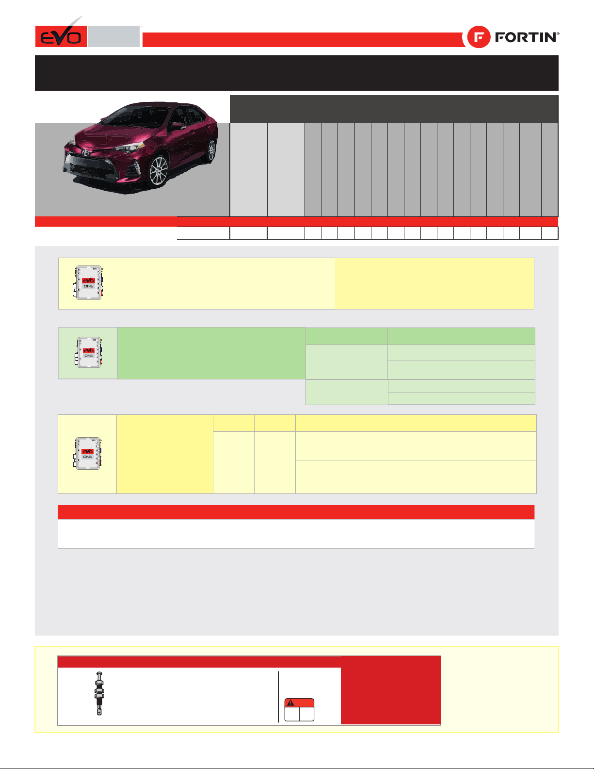
HOOD PIN HOOD STATUS: THE HOOD PIN SWITCH (INCLUDED)
MUST BE INSTALLED IF THE VEHICLE CAN BE REMOTE
STARTED WITH THE HOOD OPEN.
CONTACT
DE CAPOT
SECURITY STICKER
AUTOCOLLANT DE
SÉCURITÉ
MANDATORY INSTALL | INSTALLATION OBLIGATOIRE Notice: the installation of safety
elements are mandatory. The hood pin
and the sticker are essential security
elements and must be installed.
Notice: l'installation des éléments de
sécurité est obligatoire. Le contact de
capot et l'autocollant de sécurité sont
des éléments de sécurité essentiels et
doivent absolument être installés.
THIS MODULE MUST BE INSTALLED BY A
QUALIFIED TECHNICIAN. A WRONG
CONNECTION CAN CAUSE PERMANENT
DAMAGE TO THE VEHICLE.
CE MODULE DOIT ÊTRE INSTALLÉ PAR
UN TECHNICIEN QUALIFIÉ, TOUTE
ERREUR DANS LES BRANCHEMENTS
PEUT OCCASIONNER DES DOMMAGES
PERMANENTS AU VÉHICULE.
STATUT DE CAPOT : LE CONTACT DE CAPOT (INCLUS), DOIT
ÊTRE INSTALLÉ SI LE VÉHICULE PEUT DÉMARRER À DISTANCE,
LORSQUE LE CAPOT EST OUVERT.
Included
Inclus
ONE REV.: 20180802
ADDENDUM - SUGGESTED WIRING CONFIGURATION
ADDENDA - SCHÉMA DE BRANCHEMENT SUGGÉRÉ
Vehicle functions supported in this diagram (functional if equipped) | Fonctions du véhicule
supportées dans ce diagramme (fonctionnelles si équipé)
VEHICLE
VEHICULES
YEARS
ANNÉES
Transponder Bypass
T-Harness
Harnais en T
Lock
Unlock
Arm
Disarm
Parking Lights
Trunk (open)
Tachometer
Autolight Off
Door Status
Trunk Status
Hand-Brake Status
Foot-Brake Status
Hood Status*
R.S. OEM remote
Stand Alone compatible
OEM remote Monitoring
TOYOTA
Corolla H-KEY
2017-2019
•
•
•
•
•
•
•
•
•
•
•
•
•
•
•
•
•
GUIDE # 62031
BYPASS FIRMWARE VERSION
VERSION LOGICIELLE CONTOURNEMENT To add the rmware version and the options, use the FLASH
LINK UPDATER or FLASH LINK MOBILE tool, sold separately.
Pour ajouter la version logicielle et les options,
utilisez l’outil FLASH LINK UPDATER
ou FLASH LINK MOBILE, vendu séparément.
79.[48]
TOYOTA/LEXUS/SUBARU MINIMUM
Program remote
starter option for R.S.
OEM REMOTE STAND
ALONE:
Programmez l’option
démarreur à distance
pour TÉLÉCOMMANDE
D’ORIGINE STAND
ALONE:
FUNCTION
FONCTION MODE DESCRIPTION
38 2
Enable
Press 3x Lock to remote start with the OEM remote.
Activé
Appuyez x3 sur Verrouille de la télécommance d’origine
pour démarrer à distance le véhicule.
Program bypass option:
Programmez l’option du contournement:
UNIT OPTION
OPTION UNITE DESCRIPTION
C1
OEM Remote status (Lock/Unlock)
monitoring
Suivi des status (Verrouillage/Déverrouil-
lage) de la télécommande d’origine
Program bypass option
(If equiped with OEM alarm):
Programmez l’option du contournement
(Si équipé d’une alarme d’origine):
UNIT OPTION
OPTION UNITE DESCRIPTION
D2
Unlock before / Lock after (Disarm OEM
alarm)
Déverrouille avant / Verrouille après
(Désarme l’alarme d’origine)
D5 Lock after start
Verrouillage après le démarrage
NOTES
*Hood Status functional if equipped with a factory hood
switch.
fonctionnel si équipé d’un commutateur de capot d’origine.
Page 1 / 7
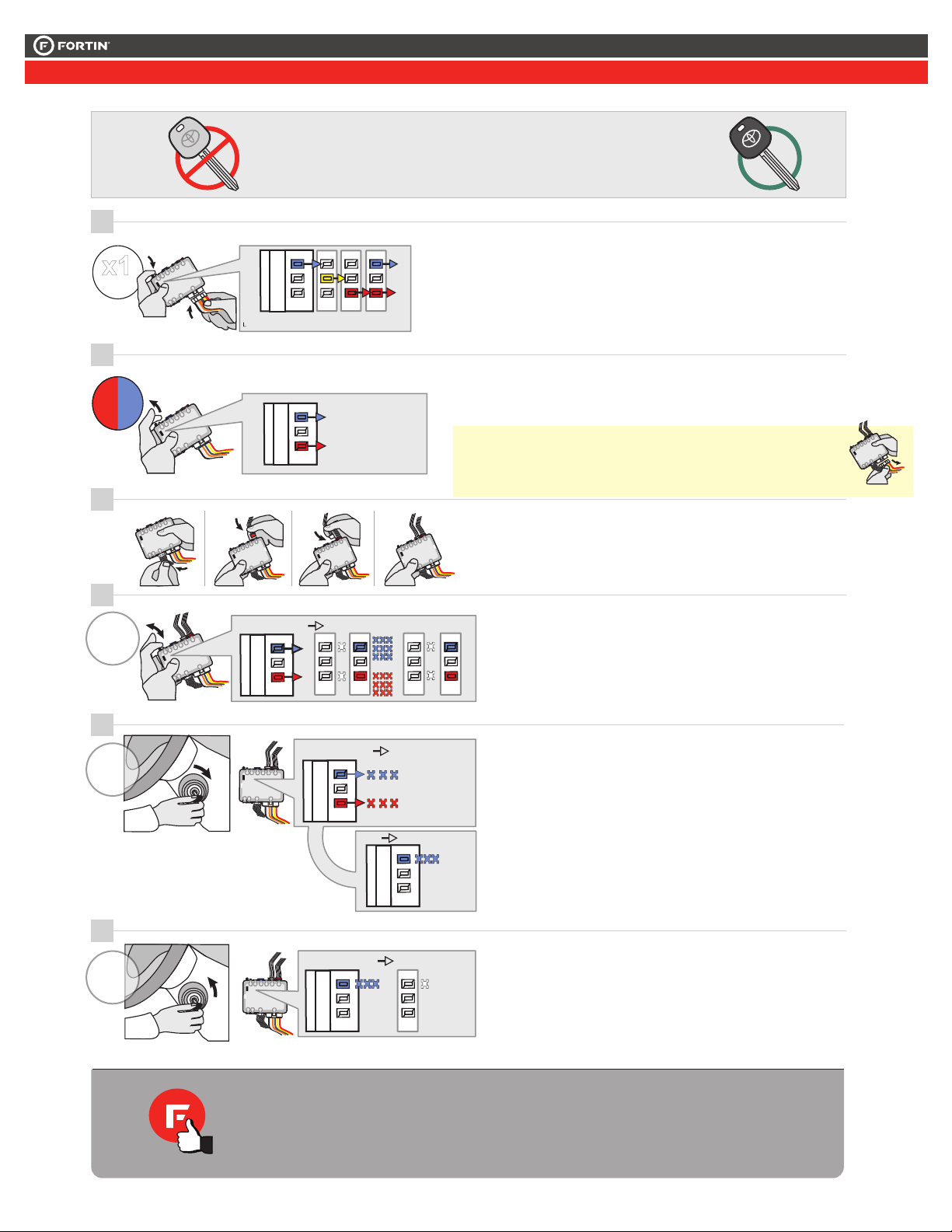
THAR-ONE-TOY3 THARNESS INSTALLATION
INSTALLATION HARNAIS THAR-ONE-TOY3
This guide may change without notice. See www.fortin.ca for latest version.
Ce guide peut faire l’objet de changement sans préavis. Voir www.fortin.ca pour la récente version.
DESCRIPTION |DESCRIPTION
Under fuse box
Sous la boîte à fusibles
Ignition switch
Commutateur d’Ignition
g
Fuse box
Boîte à fusibles
TPMS
TPMS
CONNECTION ONLY REQUIRED IF REMOTE START
CONTROL FROM OEM REMOTES IS DESIRED AND
VEHICLE IS EQUIPPED WITH TIRE PRESSURE
MONITORING SYSTEM (TPMS). CONNEXION
UNIQUEMENT REQUISE SI LE CONTRÔLE DE
DÉMARRAGE À DISTANCE DE LA TÉLÉCOMMANDES
D’ORIGINE EST DÉSIRÉ ET LE VÉHICULE EST ÉQUIPÉ
D'UN SYSTÈMES DE CONTRÔLE DE PRESSION DE PNEU
(TPMS).
Driver kick panel
Panneau latérale côté conducteur
(-)DISARM
Steering column
Colonne de direction
DATA DOOR
LOCK
Parking Light Switch
Commutateur des feux de
stationnement.
(-)PARKING
LIGHT
CAN HIGH CAN LOW
(-)DRIVER DOOR
PIN
(+)CLUTCH
SWITCH
Manual
transmission
OBD-II connector
Connecteur OBD-II
IMMO DATA
7
Page 2 / 7
Yellow In A1
Purple Out A2
Purple/White Out A3
Green Out A4
White Out A5
Orange Out A6
Orange/Black Out A7
Dk.Blue Out A8
Red/Blue In A9
Lt.Blue/Black In/Out A10
Black In A11
Pink Out A12
Yellow/Black Out A13
Brown/White In A14
Pink/Black In A15
Purple/Yellow In/Out A16
Green/White In/Out A17
Green/Red In/Out A18
White/Black Out A19
Lt.Blue In/Out A20
C5 Brown
C4 Gray/Black
C3 Gray
C2 Orange/Brown
C1 Orange/Green
D6 White/Red
D5 White/Blue
D4 White/Green
D3 Yellow/Red
D2 Yellow/Blue
D1 Yellow/Green
White Out E1
Orange Out E2
Red In E3
Black In E4
Pink In/Out E5
Yellow Out E6
This guide may change without notice. See www.fortin.ca for latest version.
Ce guide peut faire l’objet de changement sans préavis. Voir www.fortin.ca pour la récente version.
CUT LOOP FOR AUTOMATIC
TRANSMISSION MODE.
COUPEZ LA BOUCLE POUR LE
MODE TRANSMISSION
AUTOMATIQUE.
AUTOMATIC TRANSMISSION WIRING CONNECTION |SCHÉMA DE BRANCHEMENT TRANSMISSION AUTOMATIQUE
HOOD PIN
MANDATORY
CONTACT CAPOT
OBLIGATOIRE (-) Hood pin
(~)TPMS
(~)TPMS
CAN HIGH
CAN LOW
(-)Ground
(+)12V
(-) Data Door Lock
(-)Driver Door Pin
(-)Parking Lights
(~) IMMO DATA
(-)Disarm
(+)Ignion
A2
A3
A4
A5
A6
A7
A8
A9
A10
A11
A12
A13
A14
A15
A16
A17
A18
A19
A20
E1
E2
E3
E4
E5
E6
C5
C4
C3
C2
C1
D6
D5
D4
D3
D2
D1
A1
D1
D2
D3
D5
C1
C2
C5
A19
A17
A16
A14
A13
A11
A9
A8
A7
A5
A4
A3
A2
654 321
16 151718 14 13 12 11 10 9 8 7
30 29 28 24 23 22 21 20 19
DATA DOOR
LOCK
Green
Vert
A20
Back view - White
30-pin connector,
Under the fuse
box.
Vue de dos -
Connecteur Blanc,
30-pins, sous la
boîte à fusibles.
Back view -
White 40-pin
connector,
E3, fuse box.
Vue de dos -
Connecteur
Blanc,
40-pins, E3,
boîte à
fusibles.
Back view -
White 8-pin
Ignition harness
Vue de dos -
Connecteur
Blanc, 8-pins,
au connecteur
d’ignition
Back view -
Blue 5-pin
Steering
column
Vue de dos -
Connecteur
Bleu, 5-pins,
Colonne de
direction
27 26 25
(-)PARKING
LIGHTS
White
Blanc

Back view -
Parking Light
Switch Black
connector
Vue de dos -
Connecteur
Noir, Commuta-
teur des feux de
stationnement.
10
5
6
7
8
9
19
20
21
17
18
25
24
23
22
34
33
32
35
38
39
40
37
36
416
14
15
13
12
11
27
30
29
28
31
26
1
2
3
White
Blanc
(-)DRIVER
DOOR PIN
D6
D4
TPMS
Blue
Bleu
CUT
Lt.Blue
Bleu Pâle
C3 C4
CAN
HIGH
CAN
LOW
White
Blanc
12345
1
7
8
9
13
14
23456
101112
Back view -
Driver kick
panel white
connector.
Vue de dos -
Connecteur
blanc, panneau
latérale côté
conducteur.
See note
previous page
voir note page
précédente
For Autolight
shut down.
Pour la
fermeture
des lumières
automatique.
If equipped with
OEM Alarm
Si équipé
d’une Alarme
d’origine
123456789
1112131415161718
10
19
20
14
61 2 3 4 5 6 7 8
9 10 11 12 13 14 15 16
IMMO
DATA
Vert Pâle
Front view -
OBD-II
connector
Vue de face -
connector
OBD-II
Lt.Green
A10
(-)DISARM
Lt.Green
Vert Pâle
T-HARNESS - HARNAIS EN T
Ground
MALE T-HARNESS
IGNITION PLUG
CONNECTEUR D’IGNITION
DU T-HARNAISMÂLE
FEMALE T-HARNESS
IGNITION PLUG
CONNECTEUR D’IGNITION
DU T-HARNAISFEMELLE
MALE VEHICLE
IGNITION PLUG
CONNECTEUR MÂLE
D’IGNITION
DU VÉHICULE
A18A12 A6
Page 3 / 7
Yellow In A1
Purple Out A2
Purple/White Out A3
Green Out A4
White Out A5
Orange Out A6
Orange/Black Out A7
Dk.Blue Out A8
Red/Blue In A9
Lt.Blue/Black In/Out A10
Black In A11
Pink Out A12
Yellow/Black Out A13
Brown/White In A14
Pink/Black In A15
Purple/Yellow In/Out A16
Green/White In/Out A17
Green/Red In/Out A18
White/Black Out A19
Lt.Blue In/Out A20
C5 Brown
C4 Gray/Black
C3 Gray
C2 Orange/Brown
C1 Orange/Green
D6 White/Red
D5 White/Blue
D4 White/Green
D3 Yellow/Red
D2 Yellow/Blue
D1 Yellow/Green
White Out E1
Orange Out E2
Red In E3
Black In E4
Pink In/Out E5
Yellow Out E6
This guide may change without notice. See www.fortin.ca for latest version.
Ce guide peut faire l’objet de changement sans préavis. Voir www.fortin.ca pour la récente version.
MANUAL TRANSMISSION WIRING CONNECTION |SCHÉMA DE BRANCHEMENT TRANSMISSION MANUELLE
HOOD PIN
MANDATORY
CONTACT CAPOT
OBLIGATOIRE (-) Hood pin
(~)TPMS
(~)TPMS
CAN HIGH
CAN LOW
(+)Starter
(+)Ignion
(-)Ground
(+)12V
(-) Data Door Lock
(-)Driver Door Pin
(-)Parking Lights
(~) IMMO DATA
(-)Disarm
(+)Ignion
A2
A3
A4
A5
A6
A7
A8
A9
A10
A11
A12
A13
A14
A15
A16
A17
A18
A19
A20
E1
E2
E3
E4
E5
E6
C5
C4
C3
C2
C1
D6
D5
D4
D3
D2
D1
A1
D1
D2
D3
D5
C1
C2
C5
A19
A17
A16
A14
A13
A11
A9
A8
A7
A5
A4
A3
A2
654 321
16 151718 14 13 12 11 10 9 8 7
30 29 28 24 23 22 21 20 19
DATA DOOR
LOCK
Green
Vert
A20
Back view - White
30-pin connector,
Under the fuse
box.
Vue de dos -
Connecteur Blanc,
30-pins, sous la
boîte à fusibles.
Back view -
White 40-pin
connector,
E3, fuse box.
Vue de dos -
Connecteur
Blanc,
40-pins, E3,
boîte à
fusibles.
Back view -
White 8-pin
Ignition harness
Vue de dos -
Connecteur
Blanc, 8-pins,
au connecteur
d’ignition
Back view -
Blue 5-pin
Steering
column
Vue de dos -
Connecteur
Bleu, 5-pins,
Colonne de
direction
27 26 25
(-)PARKING
LIGHTS
White
Blanc

Back view -
Parking Light
Switch Black
connector
Vue de dos -
Connecteur
Noir, Commuta-
teur des feux de
stationnement.
10
5
6
7
8
9
19
20
21
17
18
25
24
23
22
34
33
32
35
38
39
40
37
36
416
14
15
13
12
11
27
30
29
28
31
26
1
2
3
White
Blanc
(-)DRIVER
DOOR PIN
D6
D4
TPMS
Blue
Bleu
CUT
Lt.Blue
Bleu Pâle
C3 C4
CAN
HIGH
CAN
LOW
White
Blanc
12345
1
7
8
9
13
14
23456
101112
Back view -
Driver kick
panel white
connector.
Vue de dos -
Connecteur
blanc, panneau
latérale côté
conducteur.
See note
previous page
voir note page
précédente
For Autolight
shut down.
Pour la
fermeture
des lumières
automatique.
If equipped with
OEM Alarm
Si équipé
d’une Alarme
d’origine
123456789
1112131415161718
10
19
20
Lt.Green
vert Pâle
(+)CLUTCH
SWITCH
Back view -
White 57-pin
connector, fuse
box,
Vue de dos -
Connecteur
Blanc, 57-pins,
boîte à fusibles
1
2
3
4
5
6
7
8
9
25
26
27
46
47
48
10
11
12
13
14
15
28
29
30
31
32
33
34
35
36
49
50
51
52
53
54
55
56
57
16
17
18
19
20
21
22
23
24
37
38
39
40
41
42
43
44
45
14
61 2 3 4 5 6 7 8
9 10 11 12 13 14 15 16
IMMO
DATA
Vert Pâle
Front view -
OBD-II
connector
Vue de face -
connector
OBD-II
Lt.Green
A10
(-)DISARM
Lt.Green
Vert Pâle
T-HARNESS - HARNAIS EN T
Ground
MALE T-HARNESS
IGNITION PLUG
CONNECTEUR D’IGNITION
DU T-HARNAISMÂLE
FEMALE T-HARNESS
IGNITION PLUG
CONNECTEUR D’IGNITION
DU T-HARNAISFEMELLE
MALE VEHICLE
IGNITION PLUG
CONNECTEUR MÂLE
D’IGNITION
DU VÉHICULE
CUT
ISOLATE
NOT CONNECTED
---------------------
ISOLEZ
NON BRANCHÉ
E6
A18A12 A6
Page 4 / 7
Insert the required remaining
connectors.
2
3
4
Insérez les connecteurs requis
restants.
LOCK
ACCON
PUSH
START
IGN
Turn the Ignition to the
ON/RUN position.
6
Turn the Ignition to the OFF
position.
LOCK
ACCON
PUSH
START
OFF
Tournez
ignition (ON).
la clé en position
Tournez la clé à OFF.


The RED and BLUE LED’s
will flash rapidly 10x times.
The BLUE LED will flash
rapidly.
Key bypass programmed.
CAN-Bus programmed.


Les DELs BLEUE et ROUGE
clignoteront 10x fois rapidement.
La DEL BLEUE clignotera
rapidement:
Contournement de clé
programmé.
Réseau CAN programmé.
 The BLUE LED will turn off.  La DEL BLEU s'éteint.
5
The module is now
programmed.
Le module est
programmé.
Use the remote of the remote
starter or security system to test
all of the supported features to
ensure proper programming.
Testez toutes les fonctions
supportées sur le véhicule avec la
télécommande du démarreur à
distance ou du système de sécurité.
1
PRESS
TURN
ON/RUN
TURN
OFF
Press and hold
Insert
the
programming button:
the 6-Pin Main connector.
Appuyez maintenir le
bouto
Insérez
et
n de programmation
enfoncé:
le connecteur
Principal à 6-broches.
 The LEDs will alternate
between BLUE, RED,YELLOW
& BLUE/RED flashes.
 Les DELS alterneront entre
un clignotement BLEU,
ROUGE, JAUNE &
BLEU/ROUGE.
x1
HOLD
A
E
F
GJ
I
H
B
C
D
LED may differ depending on the module casing.
apparence des DELS peut différer selon le boîtier du module.
A
E
F
GJ
I
H
B
C
D
A
E
F
GJ
I
H
B
C
D
A
E
F
GJ
I
H
B
C
D
A
E
F
GJ
I
H
B
C
D
A
E
F
GJ
I
H
B
C
D
FLASH 10X
NON
FLASH 10X
FLASH
FLASH 10X
A
E
F
GJ
I
H
B
C
D
IGNITION ON IGNITION OFF
OFF
IGNITIO
Ne pas utiliser la clé grise.Do not use the grey key.
Release the programming
button when the LED’s are
RED and BLUE.
Relâchez le bouton de
programmation quand les DELs
sont ROUGE et BLEU.
Si le DEL ne sont pas BLEU et
ROUGEle
connecteur 6 pins (Connecteur
principal) et au début de
l'étape 1.
débranchez
allez
If the LED’s are not solid BLUE
and RED the 6-
Pin connector (Main-
Harness) and go back to step
1.
disconnect
RELEASE
A
E
F
G
J
I
H
B
C
D
ON BLUE
BLEU
ON RED
ROUGE
A
E
F
G
J
I
H
B
C
D
Press releaseand the
programming button ten
(10x) times.
Appuyez relâchezet 10 fois le
bouton de programmation.
x10
 Les DELs ROUGE et
BLEU alterneront entre 9
clignotements et une pause.
 The RED and BLUE
LED’s will alternate between
9 flashes and a pause.
A
E
F
GJ
I
H
B
C
D
ON
PRESS X10
ON
FLASH X9
...
...
This guide may change without notice. See www.fortin.ca for latest version.
Ce guide peut faire l’objet de changement sans préavis. Voir www.fortin.ca pour la récente version.
KEY BYPASS PROGRAMMING PROCEDURE |PROCÉDURE DE PROGRAMMATION CONTOURNEMENT DE CLÉ
Page 5 / 7
This guide may change without notice. See www.fortin.ca for latest version.
Ce guide peut faire l’objet de changement sans préavis. Voir www.fortin.ca pour la récente version.
REMOTE STARTER PROGRAMMING PROCEDURE |PROCÉDURE DE PROGRAMMATION DU DÉMARREUR À DISTANCE
REFER TO THE QUICK INSTALL GUIDE INCLUDED WITH THE
MODULE FOR THE REMOTE STARTER PROGRAMMING.
RÉFÉREZ-VOUS AU GUIDE D’INSTALLATION RAPIDE INCLUS
AVEC LE MODULE POUR LA PROGRAMMATION DU DÉMARREUR
À DISTANCE.
Page 6 / 7
Service No : 000 102 04 2536
Date: xx-xx
INTERFACE MODULE
Made in Canada
PATENTS PENDING US: 2007-228827-A1
www.fortinbypass.com
HARDWARE VERSION
FIRMWARE VERSION
Module label | Étiquette sur le module
Notice: Updated Firmware and Installation Guides
Updated fi rmware and installation guides are posted on our web site on a regular
basis. We recommend that you update this module to the latest firmware and
download the latest installation guide(s) prior to the installation of this product.
Notice: Mise à jour microprogramme et Guides d’installations
Des mises à jour du Firmware (microprogramme) et des guides d’installation
sont mis en ligne régulièrement. Vérifiez que vous avez bien la dernière version
logiciel et le dernier guide d’installation avant l’installation de ce produit.
WARNING
The information on this sheet is provided on an (as is) basis with no representation or warranty of accuracy whatsoever.
It is the sole responsibility of the installer to check and verify any circuit before connecting to it. Only a computer safe
logic probe or digital multimeter should be used. FORTIN ELECTRONIC SYSTEMS assumes absolutely no liability or
responsibility whatsoever pertaining to the accuracy or currency of the information supplied. The installation in every case
is the sole responsibility of the installer performing the work and FORTIN ELECTRONIC SYSTEMS assumes no liability
or responsibility whatsoever resulting from any type of installation, whether performed properly, improperly or any other
way. Neither the manufacturer or distributor of this module is responsible of damages of any kind indirectly or directly
caused by this module, except for the replacement of this module in case of manufacturing defects. This module must be
installed by qualified technician. The information supplied is a guide only. This instruction guide may change without
notice. Visit www.fortinbypass.com to get the latest version.
MISE EN GARDE
L’information de ce guide est fournie sur la base de représentation (telle quelle) sans aucune garantie de précision et
d’exactitude. Il est de la seule responsabilité de l’installateur de vérifier tous les fils et circuits avant d’effectuer les connexions.
Seuls une sonde logique ou un multimètre digital doivent être utilisés. FORTIN SYSTÈMES ÉLECTRONIQUES n’assume
aucune responsabilité de l’exactitude de l’information fournie. L’installation (dans chaque cas) est la responsabilité de
l’installateur effectuant le travail. FORTIN SYSTÈMES ÉLECTRONIQUES n’assume aucune responsabilité suite à
l’installation, que celle-ci soit bonne, mauvaise ou de n’importe autre type. Ni le manufacturier, ni le distributeur ne se
considèrent responsables des dommages causés ou ayant pu être causés, indirectement ou directement, par ce module,
excepté le remplacement de ce module en cas de défectuosité de fabrication. Ce module doit être installé par un technicien
qualifié. L’information fournie dans ce guide est une suggestion. Ce guide d’instruction peut faire l’objet de changement
sans préavis. Consultez le www.fortinbypass.com pour voir la plus récente version.
Copyright © 2006-2018, FORTIN AUTO RADIO INC ALL RIGHTS RESERVED PATENT PENDING
TECH SUPPORT
Tél: 514-255-HELP (4357)
1-877-336-7797
ADDENDUM GUIDE WEB UPDATE | MISE À JOUR INTERNET
www.fortinbypass.com
ONE
Page 7 / 7

Other Fortin Car Alarm manuals

Fortin EVO ONE User manual

Fortin

Fortin EVO ONE User manual

Fortin EVO-ONE RF641W User manual

Fortin

Fortin EVO-ONE RF641W User manual

Fortin FTX94 User manual

Fortin

Fortin FTX94 User manual

Fortin Evo All THAR-VW2 User manual

Fortin

Fortin Evo All THAR-VW2 User manual

Fortin EVO ALL User manual

Fortin

Fortin EVO ALL User manual

Fortin EVO ONE User manual

Fortin

Fortin EVO ONE User manual

Fortin EVO-ALL User manual

Fortin

Fortin EVO-ALL User manual

Fortin EVO ALL THAR-GM1V2 User manual

Fortin

Fortin EVO ALL THAR-GM1V2 User manual

Fortin FSA-206L FSA-208 User manual

Fortin

Fortin FSA-206L FSA-208 User manual

Fortin EVO ONE THAR-ONE-KHY2 User manual

Fortin

Fortin EVO ONE THAR-ONE-KHY2 User manual

Fortin EVO ONE User manual

Fortin

Fortin EVO ONE User manual

Fortin EVO ONE User manual

Fortin

Fortin EVO ONE User manual

Fortin EVO CHR T1 User manual

Fortin

Fortin EVO CHR T1 User manual

Fortin EVO ALL User manual

Fortin

Fortin EVO ALL User manual

Fortin EVO-ONE User manual

Fortin

Fortin EVO-ONE User manual

Fortin EVO ONE User manual

Fortin

Fortin EVO ONE User manual

Fortin FTX74-1W User manual

Fortin

Fortin FTX74-1W User manual

Fortin RF642W User manual

Fortin

Fortin RF642W User manual

Fortin EVO ALL HAR-VW2 User manual

Fortin

Fortin EVO ALL HAR-VW2 User manual

Fortin THAR-CHR2 User manual

Fortin

Fortin THAR-CHR2 User manual

Popular Car Alarm manuals by other brands

Omega K9-Mundial Owner's guide & installation instructions

Omega

Omega K9-Mundial Owner's guide & installation instructions

Ultra Start MCS-100 owner's manual

Ultra Start

Ultra Start MCS-100 owner's manual

Mongoose TT1 manual

Mongoose

Mongoose TT1 manual

Winterhoff ROBSTOP operating instructions

Winterhoff

Winterhoff ROBSTOP operating instructions

Viper SmartStart VSM200 Series quick reference

Viper

Viper SmartStart VSM200 Series quick reference

AVS 3000 quick guide

AVS

AVS 3000 quick guide

Audiovox Pursuit PRO 9644a owner's manual

Audiovox

Audiovox Pursuit PRO 9644a owner's manual

Code Alarm CA-130 installation instructions

Code Alarm

Code Alarm CA-130 installation instructions

CYCLOPS PARALYSER 355 User instructions

CYCLOPS

CYCLOPS PARALYSER 355 User instructions

jablotron CL-306 Click manual

jablotron

jablotron CL-306 Click manual

Cross point NEXUS AM Technical manual

Cross point

Cross point NEXUS AM Technical manual

PURSUIT PRO-9344FT owner's manual

PURSUIT

PURSUIT PRO-9344FT owner's manual

CrimeStopper CS-2000 Installation & operating instructions

CrimeStopper

CrimeStopper CS-2000 Installation & operating instructions

Audiovox Prestige APS-15CH owner's manual

Audiovox

Audiovox Prestige APS-15CH owner's manual

ETLOC ETLOC-50 SECURITY installation manual

ETLOC

ETLOC ETLOC-50 SECURITY installation manual

Marksman Extreme X3 Installation and owner's manual

Marksman

Marksman Extreme X3 Installation and owner's manual

Cobra 8510 installation manual

Cobra

Cobra 8510 installation manual

Viper 500+ installation guide

Viper

Viper 500+ installation guide

manuals.online logo
manuals.online logoBrands
  • About & Mission
  • Contact us
  • Privacy Policy
  • Terms and Conditions

Copyright 2025 Manuals.Online. All Rights Reserved.