manuals.online logo
Brands
  1. Home
  2. •
  3. Brands
  4. •
  5. Fortin
  6. •
  7. Car Alarm
  8. •
  9. Fortin EVO ONE User manual

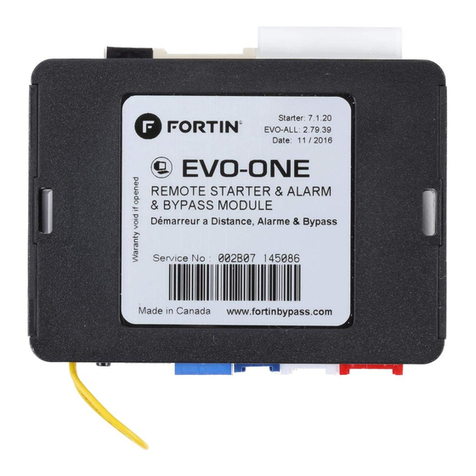
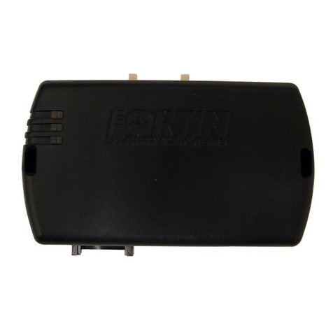
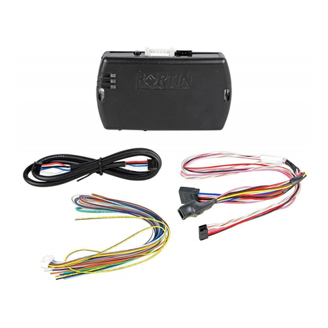
Fortin EVO ONE User manual

FLASH LINK UPDATER 2 FLASH LINK UPDATER 2
1X
Microsoft Windows Computer &
Internet connection
Ordinateur Microsoft Windows &
connection Internet
ADDENDUM - SUGGESTED WIRING CONFIGURATION
ADDENDA - SCHÉMA DE BRANCHEMENT SUGGÉRÉ
ONE REV.: 20160304
FLASH LINK UPDATER 2 FLASH LINK UPDATER 2
1X
Microsoft Windows Computer &
Internet connection
Ordinateur Microsoft Windows &
connection Internet
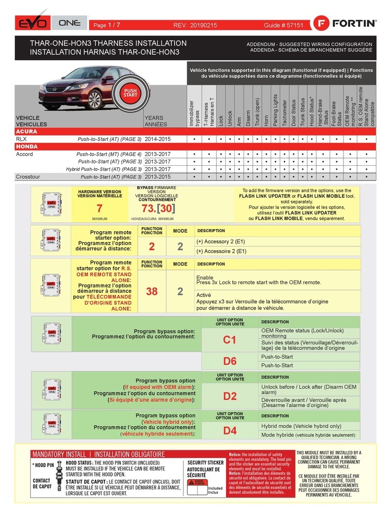
Program remote
starter option:
Programmez l’option
démarreur à distance:
FUNCTION
FONCTION MODE DESCRIPTION
22(+) Accessory 2 (E1)
(+) Accessoire 2 (E1)
NOTES
*Hood Status functional if equipped with a factory hood switch. fonctionnel si équipé d’un contact de capot d’origine.
**OEM Remote
Monitoring
The vehicle’s OEM remote will not operate while
the engine is running.
La télécommande d’origine du véhicule ne sera pas fonctionnelle
pendant que le véhicule est en marche.
BYPASS FIRMWARE VERSION
VERSION LOGICIELLE CONTOURNEMENT This manual may change without notice.
www.fortinbypass.com for latest version.
Ce Guide peut faire l’objet de changement
sans préavis. www.fortinbypass.com pour la
récente version.
73.[19]
HONDA/ACURA MINIMUM
Program bypass option
(If equiped with OEM alarm):
Programmez l’option du contournement
(Si équipé d’une alarme d’origine):
UNIT OPTION
OPTION UNITE DESCRIPTION
D2
Unlock before / Lock after (Disarm OEM
alarm)
Déverrouille avant / Verrouille après
(Désarme l’alarme d’origine)
Program bypass option:
Programmez l’option du contournement:
UNIT OPTION
OPTION UNITE DESCRIPTION
C1
OEM Remote status (Lock/Unlock)
monitoring
Suivi des status (Verrouillage/Déverrouil-
lage) de la télécommande d’origine
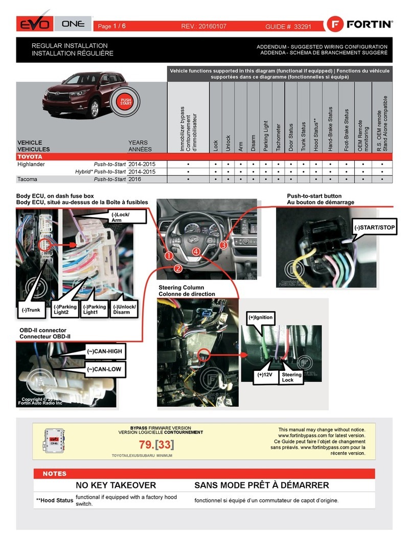
REGULAR INSTALLATION
INSTALLATION RÉGULIÈRE
Parts required (Not included) Pièce(s) requise(s) (Non incluse(s))
1X Fuse 1X Fusible
Vehicle functions supported in this diagram (functional if equipped) | Fonctions du
véhicule supportées dans ce diagramme (fonctionnelles si équipé)
VEHICLE
VEHICULES
YEARS
ANNÉES
Immobilizer Bypass
Lock
Unlock
Arm
Disarm
Trunk (open)
Horn
Parking Lights
AutoLights OFF
Tachometer
Door Status
Trunk Status
Hood Status*
Hand-Brake Status
Foot-Brake Status
OEM Remote Monitoring**
ACURA
MDX
Push-to-Start
2014-2016
•
•
•
•
•
•
•
•
•
•
•
•
•
•
•
•
TLX
Push-to-Start
2015
•
•
•
•
•
•
•
•
•
•
•
•
•
•
•
•
PUSH
START
GUIDE # 28511
Page 1 / 7
This guide may change without notice. See www.fortin.ca for latest version.
Ce guide peut faire l’objet de changement sans préavis. Voir www.fortin.ca pour la récente version.
DESCRIPTION |DESCRIPTION
At Smart PCU Module, above glove bx
Au module Smart PCU, au-dessus du coffre à gants
(-) Parking
Lights
Autolights
Off
At Parking Light Harness
Au Harnais des feux
de stationnement
(+)PTS
(+)ACCES-
SORY2 (+)ACCES-
SORY
(+)START
(+)IGNITION (~)S-NET
DATA KEY
(+)12V
(~)CAN
LOW
(~)CAN
HIGH
(-)CLUTCH*
*(-)CLUTCH
Manual transmission
Transmission manuelle
Page 2 / 7
Yellow In A1
Purple Out A2
Purple/White Out A3
Green Out A4
White Out A5
Orange Out A6
Orange/Black Out A7
Dk.Blue Out A8
Red/Blue In A9
Lt.Blue/Black In/Out A10
Black In A11
Pink Out A12
Yellow/Black Out A13
Brown/White In A14
Pink/Black In A15
Purple/Yellow In/Out A16
Green/White In/Out A17
Green/Red In/Out A18
White/Black Out A19
Lt.Blue In/Out A20
C5 Brown
C4 Gray/Black
C3 Gray
C2 Orange/Brown
C1 Orange/Green
D6 White/Red
D5 White/Blue
D4 White/Green
D3 Yellow/Red
D2 Yellow/Blue
D1 Yellow/Green
White Out E1
Orange Out E2
Red In E3
Black In E4
Pink In/Out E5
Yellow Out E6
This guide may change without notice. See www.fortin.ca for latest version.
Ce guide peut faire l’objet de changement sans préavis. Voir www.fortin.ca pour la récente version.
CUT LOOP FOR AUTOMATIC
TRANSMISSION MODE.
COUPEZ LA BOUCLE POUR LE
MODE TRANSMISSION
AUTOMATIQUE.
AUTOMATIC TRANSMISSION WIRING CONNECTION |SCHÉMA DE BRANCHEMENT TRANSMISSION AUTOMATIQUE
MDX
TLX
Grey
Gris Pink
Rose Black
Noir
Green
Vert White
Blanc
Blue
Bleu
Pink
Rose Lt.Blue
Bleu Pâle Purple
Mauve
Red
Rouge
Grey
Gris Blue
Bleu
Green
Vert
Grey
Gris
Blue
Bleu Yellow
Jaune
Pink
Rose White
Blanc
At Smart PCU Module, above glove box
Au module Smart PCU, au-dessus du coffre à gants
2
3
4
5
6
78910
1112
1
Pink
Rose Lt.Blue
Bleu Pâle
Pink
Rose Blue
Bleu
MDX : Purple - Mauve
TLX : Blue - Bleu
Tan
Beige
A7
(-)HORN
Back view. 20-pin
White connector.
At steering column.
Vue de dos.
Connecteur Blanc
20-pins.
À la colonne de direction.
2348910 567 1
121314181920 151617 11
(-)PARKING
LIGHTS
AUTO-
LIGHTS
OFF
Back View - 12-pin Blue
connector - At Parking
Lights Harness
Vue de dos - Connecteur
Bleu de 12-pins - Au
Harnais des feux de
stationnement
12131417181920 1516
23467810 9 5
(+) 12V
12
3
4
5
678
33
3435
(+)PTS
(+)ACCES-
SORY
(+)ACCES-
SORY2
(+)IGNI-
TION (+)START
910
1112
13
1417 1516
2930
31
32 1920
2122
23
24
2526
27
28
18
36
(~)S-NET
DATA KEY
A10
Back View
36-pins Grey connector
----------------------
Vue de dos
Connecteur
Gris de 36-pins
Back View
20-pins
Grey connector
-----------------
Vue de dos
Connecteur Gris
de 20-pins
1
11
(~)CAN
HIGH (~)CAN
LOW
C3 C4
1
11
Yellow/Green
Yellow/Blue
Yellow/Red
White/Green
Orange/Green
Orange/Brown
Brown
Lt.Blue
White/Black
Green/Red
Green/White
Purple/Yellow
Pink/Black
Brown/White
Yellow/Black
Black
Red/Blue
Orange
Green
Purple/White
Purple
A8A12
(+)Ignion
(-)Horn
(-)GWR
(~)S-NET DATA KEY
(-)Parking Lights
(+)Accessory2
CAN LOW
CAN HIGH
(+)Accessory1
(+)12V
(+)12V
(+)PTS
Ground
(+)Ignion
(+)Start
GROUND
10 Amp
Fuse
10AMP
E6E2E5/A1 E1E3/D6
D6
D5
White
Page 3 / 7
A
E
F
GJ
I
H
B
C
D
PROGRAMMING PROCEDURE 1/2 | PROCÉDURE DE PROGRAMMATION 1/2
Parts required (not included) Pièces requises (non incluses)
1x
1x
software
1x Microsoft Windows Computer with
Internet connection
FLASH LINK UPDATER
FLASH LINK 3.52
2
MANAGER MIN
1x
1x Programme
1x Ordinateur Microsoft Windows avec
connection Internet
FLASH LINK UPDATER
FLASH LINK 3.52
2
MANAGER MIN
4
CONTINUE TO THE NEXT PAGE | CONTINUEZ À LA PAGE SUIVANTE
5
Press and release the
programming button three
times (3x).
x3
PRESS
Appuyez et relâchez 3 fois le
bouton de programmation.
LOCK
ACC ON
PUSH
START
IGN
OFF
FLASH
IGNITION ON
FLASH
OFF
FLASH
RAPIDLY
 The Red and Yellow LEDs
will start flashing alternatively.
 Les DELs Rouge et Jaune
clignoteront alternativement.
LOCK
ACC ON
PUSH
START
OFF
A
E
F
GJ
I
H
B
C
D
PRESS X3
Honda Accord 2014 KEY
Honda Accord 2014 PTS
(MEME PORG. SAUFBOUTON)
Honda Odyssey 2014 PTS
1
2
RELEASE
3
A
E
F
GJ
I
H
B
C
D
ON BLUE
BLEU
ON RED
ROUGE
A
E
F
GJ
I
H
B
C
D
A
E
F
GJ
I
H
B
C
D
A
E
F
GJ
I
H
B
C
D
A
E
F
GJ
I
H
B
C
D
A
E
F
GJ
I
H
B
C
D
...
...
2XFLASHPAUSE PAUSE ...
A
E
F
GJ
I
H
B
C
D
ALTERNATE | ALTERNE
6
Tournez la clé à Ignition.
Turn the key to the
Ignition ON/RUN position.
Turn the key to the
OFF position.
Tournez la clé à la
position Arrêt (OFF).
Release the programming
button when the Blue & Red
LEDs are ON.
Relâchez le bouton de
programmation quand les
DELs Bleue & Rouge sont
allumées.
Si les DELs Bleue & Rouge ne sont
pas allumées, débranchez le
harnais Data-Link à 6-Broches et
retournez au début de l'étape 1.
If the Blue & Red LEDs are
not ON solid disconnect the
6-PIN Data-Link and go
back to step 1.
Connect the required
remaining harnesses.
Branchez les harnais requis
restants.
 The Red and Blue LEDs
will alternate between 2
flashes and a pause.
 Les DELs Bleue et Rouge
alterneront entre 2
clignotements et 1 pause.
 Wait for the Yellow Led to
flash rapidly.
 Attendez que la DEL Jaune
clignote rapidement.
 Wait for the Blue LED to
flash rapidly.
 Attendez que la DEL Bleue
clignote rapidement.
x1
HOLD
A
E
F
G
J
I
H
B
C
D
LED may differ depending on the module casing.
L’apparence des DELS peut différer selon le boîtier du module.
Press and hold the
programming button:
Connect
the 6-PIN Main
harness (White connector).
 The Blue, Red, Y
ellow and
Blue & Red LEDs will
alternatively illuminate.
Appuyez et maintenir le bouton
de programmation enfoncé:
Branchez le harnais Principal à
6-Pins (connecteur Blanc)
 Les DELs Bleue, Rouge,
Jaune et Bleue & Rouge
s'illumineront alternativement.
PROGRAMMING PROCEDURE 2/2 | PROCÉDURE DE PROGRAMMATION 2/2
Do not press the brake
pedal.
Press the Push-to-Start
button twice to turn on
the ignition.
IGN ON
x2
PRESS
Ne pas appuyer sur la pédale
de frein.
Appuyez 2 fois sur le bouton
démarrage (Push-to-Start)
pour allumer l'ignition.
OFF
Press the Push-to-Start
button once to turn off the
ignition.
x1
PRESS
Appuyez 1 fois sur le
bouton démarrage (Push-
to-Start) pour éteindre
l'ignition.
 BLUE LED will turn off.The  s'éteintLa DEL BLEUE
CAN-Bus programmed. Réseau CAN programmé.
FLASH LINK
UPDATER 2
FLASH LINK MANAGER
SOFTWARE | PROGRAMME
A
E
F
GJ
I
H
B
C
D
A
E
F
GJ
I
H
B
C
D
A
E
F
GJ
I
H
B
C
D
A
E
F
GJ
I
H
B
C
D
A
E
F
GJ
I
H
B
C
D
A
E
F
GJ
I
H
B
C
D
Date: xx-xx
HARDWARE VERSION : 3
FIRMWARE VERSION : 4.0+
Service No : 000 102 04 2536
INTERFACE MODULE
Made in Canada
PATENTS PENDING US: 2007-228827-A1
www.fortinbypass.com
EVO
A
E
F
GJ
I
H
B
C
D
A
E
F
GJ
I
H
B
C
D
Date: xx-xx
HARDWARE VERSION : 3
FIRMWARE VERSION : 4.0+
Service No : 000 102 04 2536
INTERFACE MODULE
Made in Canada
PATENTS PENDING US: 2007-228827-A1
www.fortinbypass.com
EVO
A
E
F
GJ
I
H
B
C
D
A
E
F
GJ
I
H
B
C
D
A
E
F
GJ
I
H
B
C
D
A
E
F
GJ
I
H
B
C
D
ALL
Microsoft Windows
Computer with
Internet connection
Ordinateur Microsoft
Windows avec
connection Internet
Pièces requises (non incluses)
Reconnect the 6-Pin Main connector
and all the remaining connectors.
Rebranchez le connecteur Principal à 6-broches
et ensuite tous les connecteurs restants du EVO-ONE.
Connect the module to the
FLASH LINK UPDATER 2
and visit the DCryptor menu
in the Flash-Link Manager .
Branchez le module au
FLASH LINK UPDATER 2
et visitez le menu DCryptor
dans le Flash-Link Manager.
Disconnect all EVO-ONE connectors.
Débranchez tous les connecteurs du EVO-ONE.
REMOTE STARTER / ALARM VERIFICATION
PROCEDURE | PROCÉDURE DE VÉRIFICATION
DU DÉMARREUR À DISTANCE / ALARME
The module is now programmed.
Le module est programmé.
Parts required (not included)
7
9
8
Test the remote starter. Remote start the vehicle.
Testez le démarreur à distance. Démarrez le véhicule à
distance.
3.52
MIN
Do not press the brake pedal.
Press the Push-to-Start button
twice to turn ON the ignition.
Press the Push-to-Start button
once to turn OFF the ignition.
Ne pas appuyer sur le pédale de
frein.
Appuyez 2 fois sur le bouton démar-
rage (Push-to-Start) pour allumer
l’ignition.
Appuyez 1 fois sur le bouton démar-
rage (Push-to-Start) pour éteindre
l’ignition.
This guide may change without notice. See www.fortin.ca for latest version.
Ce guide peut faire l’objet de changement sans préavis. Voir www.fortin.ca pour la récente version.
DCRYPTOR PROGRAMMING PROCEDURE |PROCÉDURE DE PROGRAMMATION AVEC DCRYPTEUR
Parts required (not included) Pièces requises (non incluses)
1x FLASH LINK UPDATER 2,
1x FLASH LINK MANAGER software
1x Microsoft Windows Computer with
Internet connection
1x FLASH LINK UPDATER 2,
1x Programme FLASH LINK MANAGER
1x Ordinateur Microsoft Windows avec
connection Internet
Page 4 / 7
FLASH LINK
UPDATER 2
FLASH LINK MANAGER
SOFTWARE | PROGRAMME
A
E
F
GJ
I
H
B
C
D
A
E
F
G
J
I
H
B
C
D
A
E
F
G
J
I
H
B
C
D
A
E
F
GJ
I
H
B
C
D
A
E
F
G
J
I
H
B
C
D
A
E
F
GJ
I
H
B
C
D
A
E
F
G
J
I
H
B
C
D
A
E
F
G
J
I
H
B
C
D
A
E
F
GJ
I
H
B
C
D
A
E
F
G
J
I
H
B
C
D
A
E
F
GJ
I
H
B
C
D
Microsoft Windows
Computer with
Internet connection
Ordinateur Microsoft
Windows avec
connection Internet
Pièces requises (non incluses)
Connect the module to the
FLASH LINK UPDATER 2
and visit the DCryptor menu
in the Flash-Link Manager.
Branchez le module au
FLASH LINK UPDATER 2
et visitez le menu DCryptor
dans le Flash-Link Manager.
Disconnect all connectors and after the 6-Pin (Main-Harness)
connector.
Débranchez tous les connecteurs et ensuite le connecteur
6-pins (Connecteur principal).
REMOTE STARTER / ALARM VERIFICATION
PROCEDURE | PROCÉDURE DE VÉRIFICATION
DU DÉMARREUR À DISTANCE / ALARME
The module is now programmed.
Le module est programmé.
Parts required (not included)
FLASH LINK
UPDATER 2
Test the remote starter. Remote start the vehicle.
Testez le démarreur à distance. Démarrez le véhicule
à distance.
AFTER DCRYPTOR PROGRAMMING COMPLETED
Go back to the vehicle and reconnect the 6-Pin (Main-
Harness) connector and after all the remaining connector.
APRÈS LA PROCÉDURE DE PROGRAMMATION
DCRYPTOR COMPLETÉE : retournez au véhicule et
rebranchez le connecteur 6-pins (Connecteur principal)
et après tous les connecteurs.
7
8
9
This guide may change without notice. See www.fortin.ca for latest version.
Ce guide peut faire l’objet de changement sans préavis. Voir www.fortin.ca pour la récente version.
KEY BYPASS PROGRAMMING PROCEDURE 2/2 |PROCÉDURE DE PROGRAMMATION CONTOURNEMENT DE CLÉ 2/2
Page 5 / 7

Other manuals for EVO ONE

37
Other Fortin Car Alarm manuals

Fortin EVO-ONE User manual

Fortin

Fortin EVO-ONE User manual

Fortin EVO ONE User manual

Fortin

Fortin EVO ONE User manual

Fortin EVO-ONE RF641W User manual

Fortin

Fortin EVO-ONE RF641W User manual

Fortin EVO ALL HAR-VW2 User manual

Fortin

Fortin EVO ALL HAR-VW2 User manual

Fortin EVO ALL THAR-GM1V2 User manual

Fortin

Fortin EVO ALL THAR-GM1V2 User manual

Fortin EVO ONE THAR-ONE-TOY3 User manual

Fortin

Fortin EVO ONE THAR-ONE-TOY3 User manual

Fortin EVO ONE User manual

Fortin

Fortin EVO ONE User manual

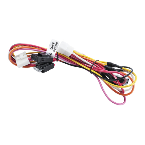
Fortin EVO ONE THAR-ONE-KHY2 User manual

Fortin

Fortin EVO ONE THAR-ONE-KHY2 User manual

Fortin FTX74-1W User manual

Fortin

Fortin FTX74-1W User manual

Fortin Evo All THAR-VW2 User manual

Fortin

Fortin Evo All THAR-VW2 User manual

Fortin EVO-ALL User manual

Fortin

Fortin EVO-ALL User manual

Fortin EVO ONE User manual

Fortin

Fortin EVO ONE User manual

Fortin FSA-206L FSA-208 User manual

Fortin

Fortin FSA-206L FSA-208 User manual

Fortin EVO CHR T1 User manual

Fortin

Fortin EVO CHR T1 User manual

Fortin EVO ONE User manual

Fortin

Fortin EVO ONE User manual

Fortin FTX94 User manual

Fortin

Fortin FTX94 User manual

Fortin RF642W User manual

Fortin

Fortin RF642W User manual

Fortin THAR-CHR2 User manual

Fortin

Fortin THAR-CHR2 User manual

Fortin EVO ALL User manual

Fortin

Fortin EVO ALL User manual

Fortin EVO ALL User manual

Fortin

Fortin EVO ALL User manual

Popular Car Alarm manuals by other brands

jablotron Athos CA-1202 user manual

jablotron

jablotron Athos CA-1202 user manual

Audiovox AVX1B4S Programming guide

Audiovox

Audiovox AVX1B4S Programming guide

Clifford 3606X owner's guide

Clifford

Clifford 3606X owner's guide

Clifford Nova 3 owner's manual

Clifford

Clifford Nova 3 owner's manual

Ultra Start 2500M SERIES install guide

Ultra Start

Ultra Start 2500M SERIES install guide

Viper 560XV owner's guide

Viper

Viper 560XV owner's guide

Ultra Start 650 Series owner's manual

Ultra Start

Ultra Start 650 Series owner's manual

Audiovox Prestige Platinum+ APS-511C owner's manual

Audiovox

Audiovox Prestige Platinum+ APS-511C owner's manual

Sparkrite SRA8 Guide

Sparkrite

Sparkrite SRA8 Guide

Federal Signal Corporation Pathfinder Siren Series Installation and maintenance manual

Federal Signal Corporation

Federal Signal Corporation Pathfinder Siren Series Installation and maintenance manual

Falcon Predator XL3 Installer manual

Falcon

Falcon Predator XL3 Installer manual

Audiovox Auto Security XR91 Programming guide

Audiovox

Audiovox Auto Security XR91 Programming guide

Clifford Sabre II owner's manual

Clifford

Clifford Sabre II owner's manual

SECO-LARM 300C owner's manual

SECO-LARM

SECO-LARM 300C owner's manual

CrimeStopper CS-8717 Wiring diagram

CrimeStopper

CrimeStopper CS-8717 Wiring diagram

Python 660XP owner's guide

Python

Python 660XP owner's guide

Scytek electronic Vectra X3 product manual

Scytek electronic

Scytek electronic Vectra X3 product manual

Clifford CYBER 2 owner's manual

Clifford

Clifford CYBER 2 owner's manual

manuals.online logo
manuals.online logoBrands
  • About & Mission
  • Contact us
  • Privacy Policy
  • Terms and Conditions

Copyright 2025 Manuals.Online. All Rights Reserved.