1
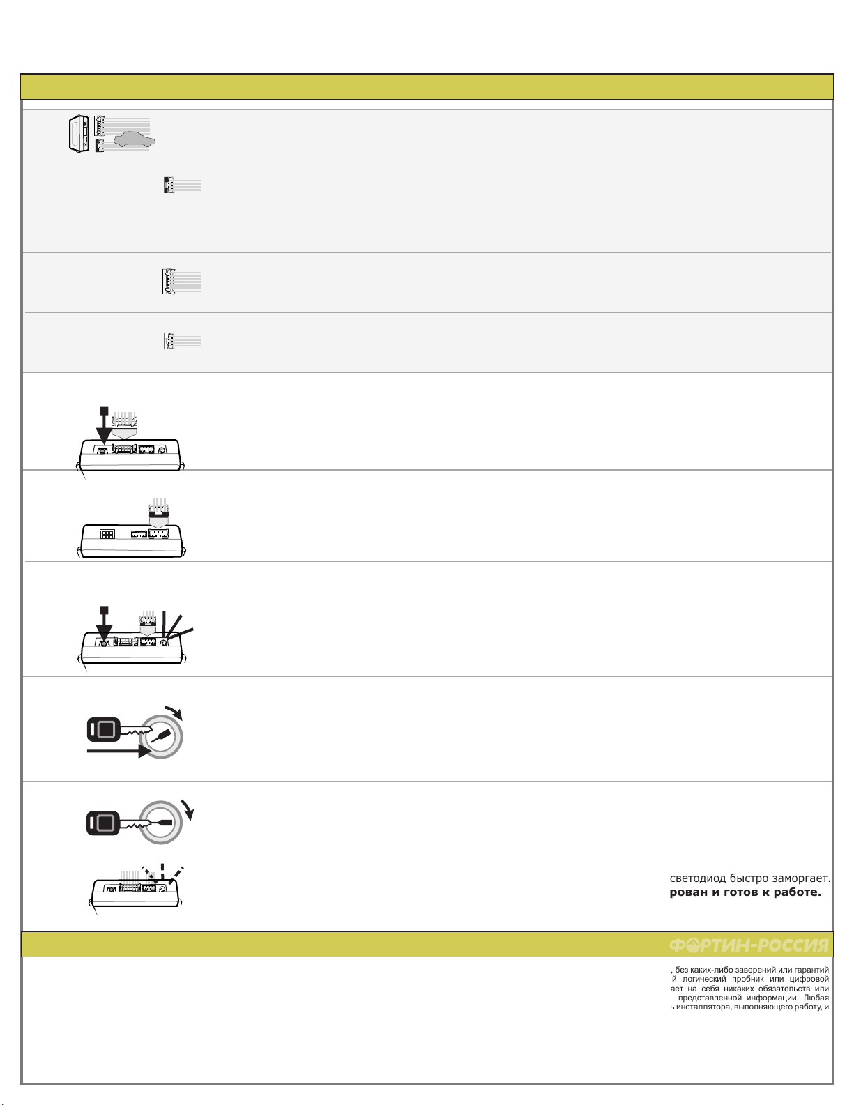
1.C
1.B
5
Still pressing the programming switch:
insert the main wires harness (CONN 1)
into the key-override-all module.
3
2
Press the programming switch while
connect the connectors 2
into the key-override-all module.
2
3
Connector 3 (White, located at the back of the
module):
Make the connections
1.A
Connector 2 (White):
Make the connections
6
4
1
Make the connections of the KEY-
OVERRIDE-ALL to the vehicle:
Still pressing the programming
switch:
connect the connectors 3
into the key-override-all module.
Connector 1 (Black):
Determine the type of installation:
INSTALLATION WITH DATA-LINK (See P.1)
INSTALLATION WITHOUT DATA-LINK (See P.1)
Удерживая кнопку,
вставьте главный разъем (Разъем 1).
Удерживая кнопку,
вставьте следующий разъем (Разъем 3).
Release the programming button
.
when the
LED turns ON
Turn the key to the "ON" position.Поверните ключ в положение «ON».
START
IGN
OFF
After few seconds the LED will flash rapidly.
The module is programmed.
Start the vehicle with the key. Заведите автомобиль ключом.
Через несколько секунд светодиод быстро заморгает.
Модуль запрограммирован и готов к работе.
WARNING / ВНИМАНИЕ
START
IGN
OFF
Copyright © 2010-2011
KEYOVERRIDEALL ДОПОЛНИТЕЛЬНОЕ РУКОВОДСТВО
В е б - с а й т :
Made in Canada | Сделано в Канаде - Версия C - 12/08/2011
h t t p : / / w w w . i f a r . c a
TOYOTA HILUX G Key 4/6 цил.
к автомобилю:
УПРАВЛЕНИЕ ПО КАБЕЛЮ DATA-LINK (см. стр.1)
Определите тип установки
Подключите модуль KEY-OVERRIDE-ALL
Разъём 1 (Черный):
УСТАНОВКА БЕЗ DATA-LINK (см. стр.1)
Разъём 2 (Белый):
Сделайте подключения.
Разъём 3 (Белый, расположен на задней
стороне модуля
Сделайте подключения.
):
Нажмите и удерживайте кнопку
программирования при подключении
Разъёма 2 к модулю.
Когда светодиод загорится,
отпустите кнопку для программирования.
The information on this sheet is provided on an (as is) basis with no representation or warranty of accuracy
whatsoever. It is the sole responsibility of the installer to check and verify any circuit before connecting to it. Only a
computer safe logic probe or digital multimeter should be used. FORTIN Electronic system assumes absolutely
no liability or responsibility whatsoever pertaining to the accuracy or currency of the information supplied. The
installation in every case is the sole responsibility of the installer performing the work and FORTIN Electronic
system assumes no liability or responsibility whatsoever resulting from any type of installation, whether
performed properly, improperly or any other way. Neither the manufacturer or distributor of this module is
responsible of damages of any kind indirectly or directly caused by this module, except for the replacement of this
module in case of manufacturing defects. This module must be installed by qualified technician. The information
supplied is a guide only. This instruction guide may change without notice. isit www.ifar.ca to get latest version.
Информация в данном руководстве приводится как базовая, без каких-либо заверений или гарантий
точности. Используйте только безопасный компьютерный логический пробник или цифровой
мультиметр. FORTIN ELECTRONIC SYSTEMS не принимает на себя никаких обязательств или
ответственности, относящиеся к точности и актуальности представленной информации. Любая
установка производится на исключительную ответственность инсталлятора, выполняющего работу, и
FORTIN ELECTRONIC SYSTEMS не несет обязательств или ответственности, безотносительно к типу
выполненной установки: надлежащей, ненадлежащей или любой иной. Ни производитель, ни
дистрибьютор этого модуля не несут ответственности за повреждения любого типа, прямо или
косвенно вызванные данные этим модулем, за исключением замены модуля в случае
производственного дефекта. Этот модуль должен быть установлен квалифицированным техником.
Эта информация предоставлена как справочная. Руководство может меняться без предупреждения.
Посетите www.fortinbypass.com чтобы получить последнюю версию.
ДОПОЛНЕНИЕ - SUGGESTED WIRING CONFIGURATION / ПРЕДЛАГАЕМАЯ СХЕМА ПОДКЛЮЧЕНИЯ


