STC GZ3D User manual

of 241
www.stcny.com
Systems Trading Corporation
450 7th Avenue Suite 2809, New York, NY 10123
Customer service: (877)782 4482
5
7’1” 9’4.7”
10’7”
10’7”
11’4.6”
11’4.6”
Assembly Instructions
Gazebo GZ3D
Aluminium Composite Roof Panels

of 24of 24 32 www.stcny.comwww.stcny.com
1
1
1
2
3
4
6
7
8
5
Introduction
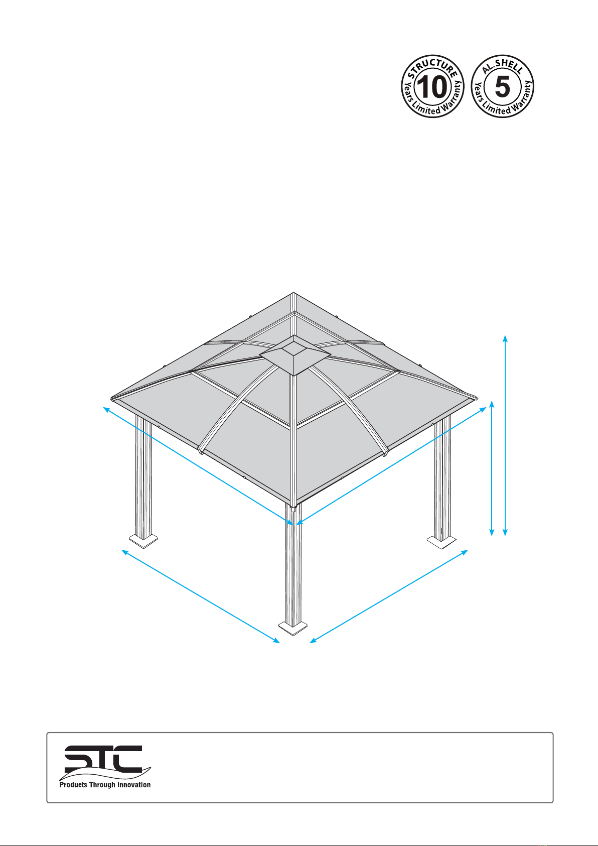
Thank you for purchasing the Gazebo GZ3D.
When properly assembled and maintained, this gazebo will provide many years of enjoyment!
These instructions include helpful hints and important information needed to safely assemble and properly
maintain the gazebo. Please read these instructions completely before you begin.
Our patented gazebo has been designed for easy assembly. All steps can be completed by a team of
four people. The assembly should take about two hours.
Before Starting Assembly:
CAREFULLY READ ALL THE INSTRUCTIONS BEFORE YOU BEGIN AND FOLLOW THE
STEPS IN THE ORDER THEY ARE PRESENTED.
1. Make sure you have all the necessary parts:
Compare the contents of the three cartons to the List of Parts. If any parts are missing or damaged, or
you have any questions, please contact Customer service: (877)782 4482 before beginning assembly.
2. Lay the parts out in separate staging areas:
The List of Parts has the corresponding step number referenced to each part. We recommend that
while you go through the list, make staging areas for each step and place the parts necessary for
eachstepintheseareas.Thiswillsaveyoutimeandeortduringassembly.
3. Select a Location:
Whenselectingalocationforyourgazebo,aatlevelareaisessentialandifpossiblewithproper
water drainage and easy access to power and water, if neccessary.
Choose a sunny, level position away from overhanging trees and power lines and protected from the
wind as much as possible.Locate underground pipes or cables before preparing the site or anchoring
the gazebo.
Note:Youmayassemblethegazeboonahardlevelsurfaceandmoveittoitsnallocationwhen
nished.Makesurethattherearenoobstaclesbetweentheassemblyareaandthenalposition.
4. Prepare a Foundation:
After choosing a location, proper preparation of the site is recommended. The site must be level.
If the site is not level, create a base slightly larger than the outside dimensions of the gazebo using a
perimeteroftwobyfourslledwitheithersoil,sodorgravel.
Make sure the base is square by measuring the diagonals from both directions and making sure
they are equal. The gazebo is secured with pegs into holes cast with concrete.
Ifyoudecidetohaveaconcretebase,itisbesttocontactareliablecontractortomakesureitisat
and level. Make sure you have checked with your local authorities regarding any required building
permits.
5. Make sure you have the proper tools:
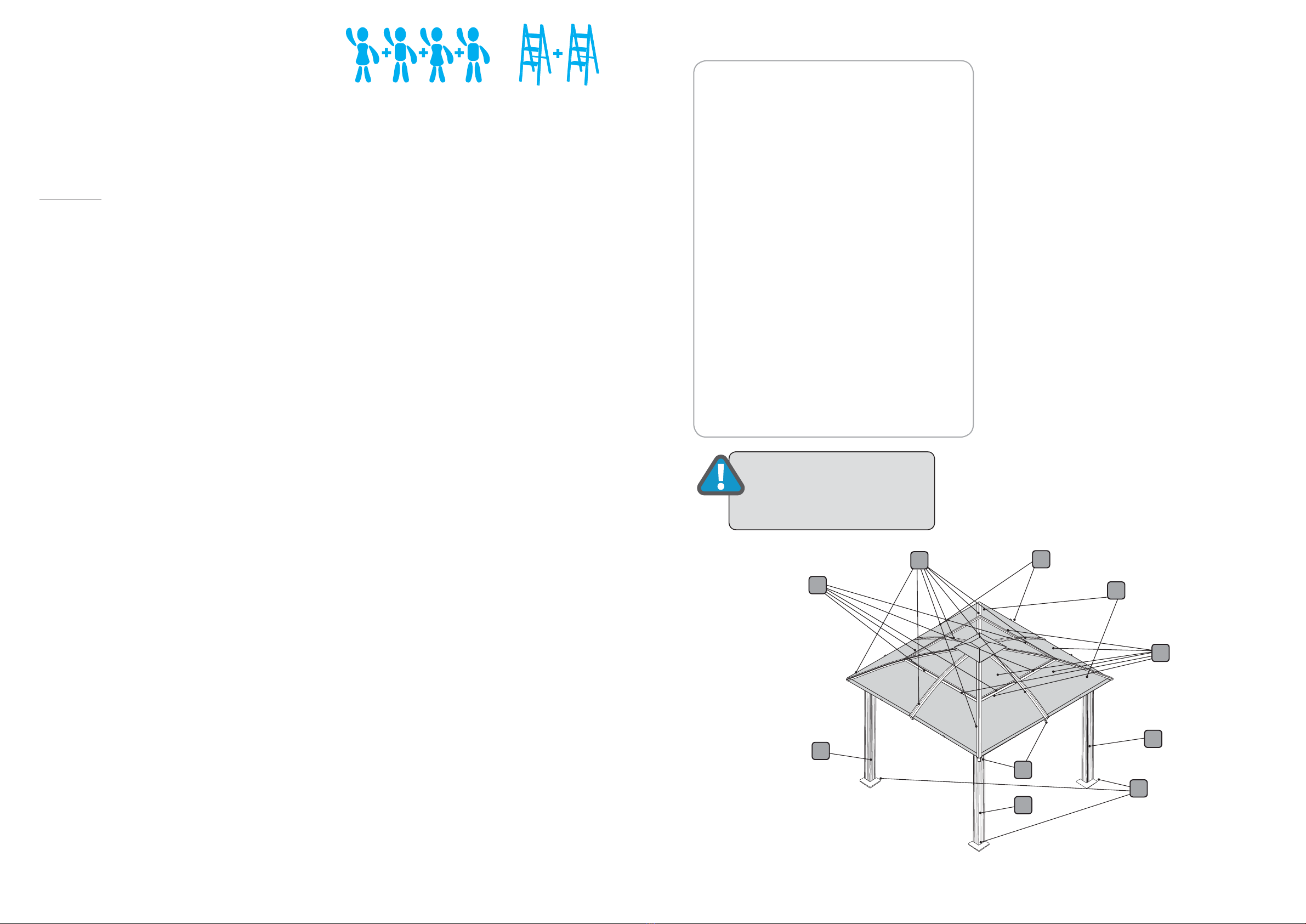
• Tape Measure • 2 Small Step Ladders
• Work Gloves • Wooden Mallet
• Safety goggles • Scissors
• Phillips Screwdriver • Liquid soap or WD40 Lubricant
• Spirit Level • Hex Key (included)
NOTE: A cordless drill with Phillips head bit is highly recommended but not essential.
Safety Advice
•
Thegazebomustbepositionedandxed
onaatlevelsurface.
•
Dispose of all plastic bags safely. Keep
them out of the reach of children.
•
Keep children and pets away from the
assembly area until the work is completed.
•
Always wear shoes, gloves and safety
goggles when working.
•
Take special care not to touch overhead
powerlineswiththealuminiumproles.
•
Do not attempt to assemble the gazebo in
windy or wet conditions.
•
Do not position your gazebo in an area
exposed to excessive wind.
•
If using power tools or a ladder, always fol-
low the manufacturers safety instructions.
•
Hot items such as recently used grills,
blowtorches etc. must not be stored in the
gazebo.
•
Make sure the gazebo complies with local
building codes.
Table of Contents
Introduction................................................. 2
Table of Contents......................................... 3
List of Parts.................................................. 4
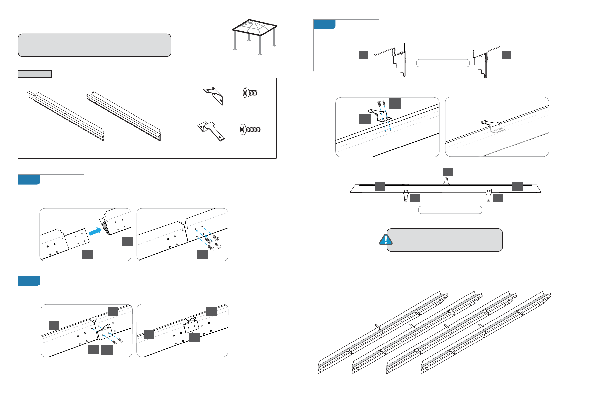
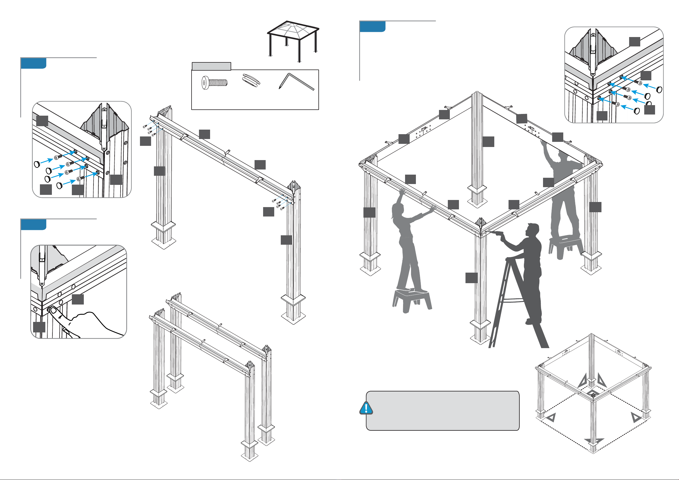
Step 1AssemblingtheCornerProles................. 6
Step 2 Assembling the Rails............................... 8
Step 3
AttachingtheRailstotheCornerProles
......... 10
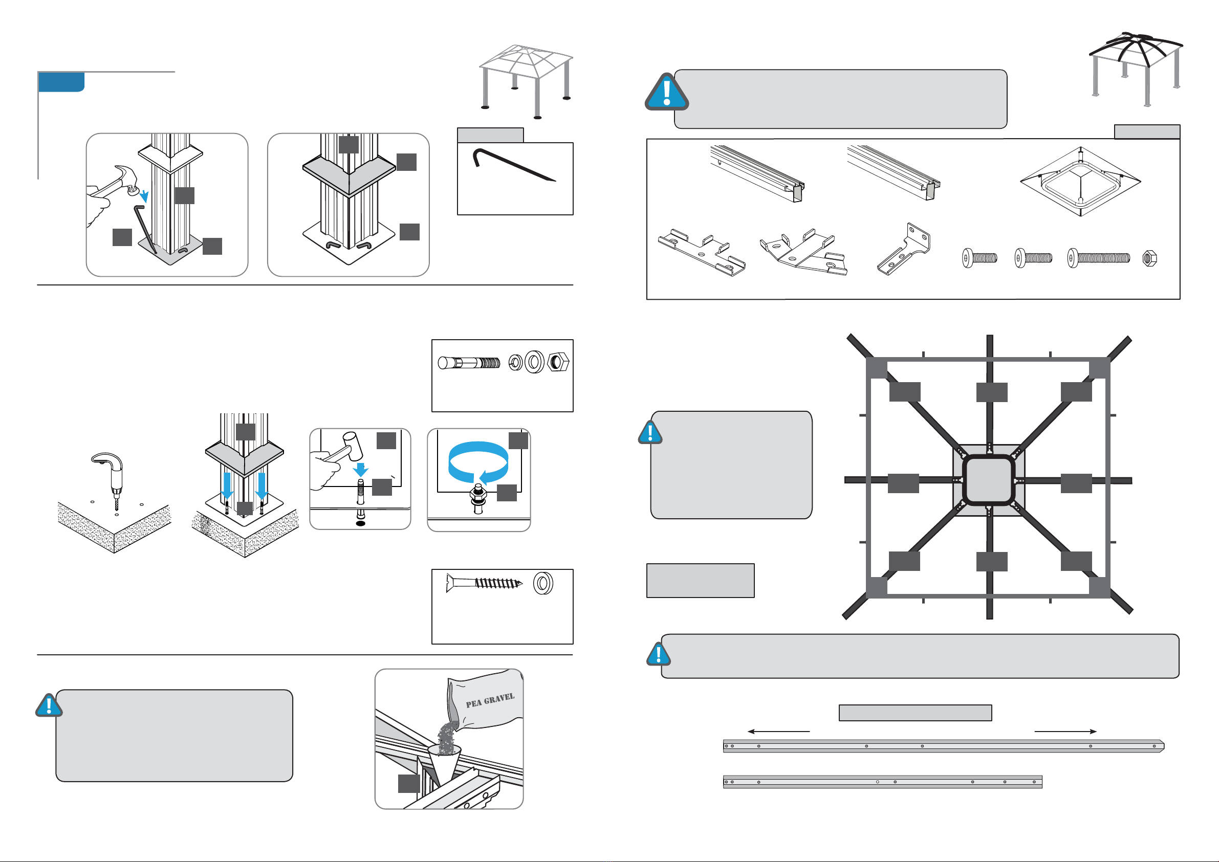
Step 4 Securing the Gazebo to the ground......... 12
Step 5
InstallingtheLowerRoofgableProles
.. 13
Step 6
InstallingtheLowerHorizontalRoofProles..
16
Step 7
Installing the Roof Panels and
UpperRoofProles.............................. 17
Step 8
Installing the Plastic Caps......................... 22
General Order of Assembly
Step1: AssemblingtheCornerproles
Step 2: Assembling the Rails
Step 3: Attaching the Rails to the Corner Pro-
les
Step 4: Securing the gazebo to the ground
Step5: InstallingtheLowerRoofGableProles
Step6:
InstallingtheLowerHorizontalRoofProles
Step 7: Installing the Roof Panels and
UpperRoofProles
Step 8:
Installing the Plastic Caps
ATTENTION: DO NOT
ATTEMPT TO ASSEMBLE
THE GAZEBO ALONE!

of 24of 24 54 www.stcny.comwww.stcny.com
Roof top connector
16A
16
17
998mm
1008mm
1008mm
998mm
17A
10A 1537mm
10
No. Prole Qty
Step
10A
10
4
4
5,7
11
4
7
12
4
7
13 4
7
14 4
7
15 1
5
16A
16
4
4
6,7
17A
17
4
4
6,7
No. Prole Qty
Step
1 4
1
2 4
1
3 4
1
4 4
1
5 4
2
64
2
7 4
2
8 8
2
9A
9
4
4
5,7
2190mm
1808mm
1633mm
Corner
Prole
Support Frame
Support Plate
Corner Roof
Connector
Rail
Rail
Outer Roof Connector
Roof
GableProle
2175mm
We included some extra screws and bolts for your convenience.
Screw ø 4*8
T- connector A
T- connector B
9A
2107mm
9
Inner Roof Connector
Horizontal
RoofProle
Horizontal
RoofProle
Aluminium Composite
Roof Panel
Aluminium Composite
Roof Panel
Aluminium Composite
Roof Panel
Aluminium Composite
Roof Panel
Roof
GableProle
1562mm
black
side
black
side
black
side
ScrewM6*8
ScrewM6*18
ScrewM6*12
ScrewM6*25
ScrewM6*38
Plastic Cap #1
Plastic Cap #2
NutM6
Plastic Cap #3
Ground Spike
Concrete Bolt
Spanner
Magnetic Hex Key
black
side
Roof Top Cover
The gazebo is shipped in three cartons. These cartons are heavy. Be careful when lifting them.
Wear proper safety gear including work shoes, gloves and goggles.
Thepartsareidentiedbyremovablestickers.
Place all the parts for each step in staging areas, checking that you have all parts as you go.
If any parts are missing or damaged, contact STC customer service before beginning assembly:
No. Prole Qty
Step
28 16
4
29
16
4
30 1
31 1
32 4
6
33 4
6
34 8
5
No. Prole Qty
Step
18 16
19 16
20 100
21 24
22 64
23 8
6,7
24 8
25 32
6,7
26 4
8
27 4
8
List of Parts

of 24of 24 76www.stcny.comwww.stcny.com
3
21
1
21
1 1 1 1
3
2
1
x 4
1 1 1 1
11
4
21 21
4
x 4
1.B
1.A
11
AssemblingtheCornerProles
Place all the parts on a level surface
.
Make sure the pieces are in the correct positions before assembling.
Carefully follow the order of assembly to ensure an easy installation.
Wear proper safety gear including work shoes, gloves and goggles.
STEP 1
Slidesupportframes(2)overlowerendofcornerproles(1).
Attachsupportplates(3)tocornerprolesasshown,usingfourscrews(21)foreachplate.
Leavesupportframes(2)about10”overlowerendofcornerproles(1)untilstep4(
Securing
the gazebo to the ground)
Components
Cornerprole(1)
x 4
Support plate (3)
x 4
Roof connector (4)
x 4
Support frame (2)
x 4
Screw (21)
x 24
Placecornerproles(1)paralleltoeachothertheground.Attachoneroofconnector(4)toeachtop
end as shown and fasten with screws (21).
ATTENTION:
Thecornerprole(1)hastwoscrew
holes to connect it to the roof connector (4)
and8pre-drilledscrewholestoattachrails(5,6)in
step 3 at its top end.
It has four screw holes to connect it to the support
plate (3) at its bottom end.
Top end Bottom end

of 24of 24 98 www.stcny.comwww.stcny.com
5
5
5
5
6
6
6 6
7
7
18
20
20
8
8
8 8
Inner Roof Connector (7)
x 4
Outer Roof Connector (8)
x 8
Attach two outer roof connectors (8) to each rail set at pre-drilled screw holes, using screws (20).
VIEW FROM THE TOP
ATTENTION: Attach roof connectors
facing exactly in the directions shown.
7
7
2.C
2.A
2.B
x 4
Assembling the Rails
Insertconnectingpartofrail(5)intobluntendofrail(6)asshown.
Attach with four screws (18).
Repeat to create four sets of rails.
STEP 2
Components
Rail (5)
x 4
Rail(6)
x 4
Screw (20)
x 24
Screw (18)
x16
NOTE:
The Rails (5) have a preassembled connecting
partstobeinsertedintoRails(6).
Attach inner roof connector (7) to each rail set as shown, using two screws (20).
VIEW FROM SIDE

of 24of 24 1110 www.stcny.comwww.stcny.com
20
20
20
25
25
1
1
1
1
6
5
5
6
6
6
6
5
5
5
5
3.A
3.B
3.C
6
1
1
20
25
1
1
1
x 2
Components
Attachoneroofproleset(5+6)totwocorner
proles(1)asshown,usingscrews(20)and
supplied magnetic hex key (30) through holes in
proleset.
Attaching the Rails to the Corner
Proles
STEP 3
Repeat step 3.A and 3.B
to create two sets.
Screw (20)
x 32
Plastic Cap #3 (25)
x 32
Magnetic Hex Key
(30)
x 1
Closeholesinproleset
with plastic caps #3 (25).
IMPORTANT: After this step you should place the
gazebo frame in its desired location.
Make sure all corners are squared at 90 degrees.
Using at least 3 people, attach the remaining two roof
prolesets(5+6)tocornerproles(1),connectingallfour
cornerproles(1).
Fasten with four screws (20) and supplied magnetic hex
key (30) on each side.
Closeholesinprolesetswithplasticcaps#3(25).

of 24of 24 1312 www.stcny.comwww.stcny.com
Roof Top Cover (15)
x 1
RoofGableProle
(9)
2175mm
x 4
RoofGableProle
(10)
1562mm
x 4
4.A
1
3
3
28
2
1
Components
11 1
29
29
29
Components
9 9
1010
10
10
9 9
1.
1.
1.
1.
2. 2.
2.
2.
Components
1
Fasten the gazebo frame to the ground, using four spikes (28) for each
support plate.
Lower support frames (2) to cover support plates (3).
Ground spike (28)
x16
Securing the Gazebo to a Concrete Floor or Wood Deck
Optional
Concrete bolts, washers and nuts
(29)
x16
Wood Bolts, washers x16
NOT SUPPLIED
to be purchased by user
Concrete Floor:
1.Usingaconcretedrill,drillholesintotheconcreteoor,
corresponding to the holes in support plates (3).
2.
Insert concrete bolts (29) into the holes and hammer into place, using a mallet.
3. Fasten concrete bolts with washers and nuts.
Wood Deck:
1.Usinganelectricwooddrill,drillholesintothewoodoor,
corresponding to the holes in support plates (2).
2.
Insert wood screws with washers (not supplied) into the holes and fasten,
using an electric screw driver.
NOTE: After securing the gazebo to the
ground,wehighlyrecommendllingthe
cornerproles(1)with2bags(20LBs
each) of Pea Gravel each for extra stability,
as shown.
Securing the Gazebo to the GroundSTEP 4 STEP 5
Using at least three people,
install the roof gables (9,10)
in the following order:
BOTTOM VIEW OF PROFILES
InstallingtheLowerRoofGableProles
NutM6(24)
x 8
Screw (20)
x 28
Screw (19)
x16
Screw (22)
x 8
RoofGableProle
(9)
Upper end Lower end
RoofGableProle
(10)
1562mm
2175mm
IMPORTANT:Makesurethattheroofgableproles(9,10)areinstalledexactlyasshownsothatthe
pre-drilled screw holes will align properly with screw holes on the roof panels.
T- connector A (32)
x 4
T- connector B (33)
x 4
Roof top connector (34)
x 8
VIEW FROM BELOW
(from inside gazebo)
ATTENTION:
DO NOT ATTEMPT TO
ASSEMBLE THIS
ALONE !
ATTENTION:
RoofProles,roofpanels
and gables must be aligned
properly during assembly
to minimize any possibility
of leaking.

of 24of 24 1514 www.stcny.comwww.stcny.com
ILLUSTRATION
20
20
32
32
3232
32
33 33
33
33
10
5,6
33
10
9
9
9
10
1
4
22
20
15
15
20
34
34
34
34
3434
34
34
3434
34
34
19 19
19
19
15
15
24
34
34
34
5.B
5.C
5.D
20
7
9
VIEWS FROM BELOW
5.A
Usingscrews(22)andnuts(24),connectroofgableproles(9)toroofconnectors(4)ontop
ofcornerproles(1).
Installroofgableproles(10).
Usingscrews(20)connectproles(10)toinnerroofconnectors(7)onprolesets(5,6)andthe
other end to remaining connectors (34) on roof top cover (15).
AttachT-connectorsA(32)toundersideofroofgableproles(10),usingscrews(20)asshown.
AttachT-connectorsB(33)toundersideofroofgableproles(9),usingscrews(20)asshown.
Usingscrews(20),connectroofgableproles(9)torooftopconnectors(34)
on the four corners of roof top cover (15).
Using screws (19), connect all eight roof top
connectors (34) to roof top cover (15) as shown.
ILLUSTRATION
VIEW FROM BELOW

of 24of 24 1716 www.stcny.comwww.stcny.com
Aluminium Composite
Roof Panel (14)
x 4
Aluminium Composite
Roof Panel (13)
x 4
RoofProle(16)
1008mm
x 4
RoofProle(17)
1008mm
x 4
9
10
10
32
32
32
33
33
33
33 16
17
17
16
10
10
9
9
9
8
23
VIEW FROM BELOW
9
11
10
white
side
Screw (20)
x16
10
32
16
20 20
17
32
17
16
10
9
33
1716
2020
6.A
7.A
InstallingtheHorizontalRoofProles
InstallingtheRoofPanelsandUpperRoofProles
STEP 6 STEP 7
Components
Fitroofpanel(11)ontopofroofproles(9,10and16)asshownand
fasten with one screw (23) from below to outer roof connector (8).
Fitroofpanel(13)ontopofroofproles
(9,10and16)towardstopofgazeboasshown.
We recommend curving the roof panels
SLIGHTLY as shown below, to facilitate
fitting them onto the curved roof profiles.
VIEWS FROM BELOW
black
side
black
side
Aluminium Composite
Roof Panel (12)
x 4
Aluminium Composite
Roof Panel (11)
x 4
Components
Screw (23)
x 8
black
side black
side
VIEW FROM TOP
IMPORTANT: Remove protective plastic from both sides of roof panels.
Place with black surface toward the sun facing out when installing.
Fasten from inside the gazebo, using screws (20) as shown.
ATTENTION:
RoofProles,roofpanels
and gables must be aligned
properly during assembly
to minimize any possibility
of leaking.
ATTENTION:
RoofProles,roofpanelsandgablesmustbe
aligned properly during assembly to minimize
any possibility of leaking.
Attachroofgableproles(16,17)toT-
connectors A (32) and B (33), placing ends
intocut-outsongutterproles9and10as
shown.
13
13
11
9
9
10
10
16

of 24of 24 1918 www.stcny.comwww.stcny.com
RoofProle(16A)
998mm
x 4
RoofProle(17A)
998mm
x 4
RoofGableProle(9A)
2107mm
x 4
RoofGableProle
(10A)
1537mm
x 4
8
23
9
12
16A
16A
16
16
17
22
22 22
32
33
11
12
11
10
10
10
9
9
9
13
14
13
7.B
7.D
Placeroofprole(16A)ontopofroofprole(16)asshownand
fasten with three screws (22) from below (inside gazebo).
VIEW FROM TOP
VIEW FROM BELOW
(from inside gazebo)
Connecting the upper
andlowerproles
Components
Screw (22)
x56
7.C
VIEW FROM BELOW
Fit roof panel (12) on top of roof
proles(9,10and16)asshownand
fasten with one screw (23) from be-
low to outer roof connector (8).
Fitroofpanel(14)ontopofroofproles
(9,10 and 17) towards top of gazebo
as shown.
VIEW FROM BELOW
(from inside gazebo)
Placeroofprole(17A)ontopof
roofprole(17)asshown.
Alignbothproles.
Fasten with three screws (22)
from below (inside gazebo).
14
12
22
22
22
33
17A
17
17
16
9
9
32

of 24of 24 2120 www.stcny.comwww.stcny.com
14
7.E 7.F
7.G
VIEW FROM TOP
16A 17A
17A
17A
16A
16A
16A
11
11
12 11
12
1112
10A
10A
10A10A
9A 9A
9A 9
13
13
14
1314
13
14
22
22
22
9
10
VIEW FROM BELOW
(from inside gazebo)
Slideroofprole(9A)intorailsontopofroofprole(9)
from lower end towards top of gazebo as shown.
Fasten with four screws (22) from below.
VIEWS FROM BELOW
33
22
17
15
16
9A
99
Continue in a clock-wise direction as
shown, until the last two panels:
Place the upper roof panel.
Place the lower roof panel, secure with
one screw (23) from below.
Placetheroofgableprole,fastenwith
four screws (22) from below.
Place the last upper roof panel (14)
.
Placethelastroofgableprole(9A)on top of
(9), fasten ONLY AT THE TOP END
with 1 screw (22) from below
roofprole(9).
Positions of screws (22) from below roof.
9A
10A
17

of 24of 24 2322 www.stcny.comwww.stcny.com
7.H
Slightly lifting the
roofgableproles(9Aand10A),
place the lower roof panel (12) and secure with one screw
(23) from below.
Fasten
the
roofgableproles(9Aand10A)attheir lower end with screws (22) from below.
Placethehorizontalroofprole(17A) carefully
from above as shown, fasten with three
screws (22) from below.
ENJOY YOUR
COMPLETED GAZEBO !
26 27
9
10
Components
Closeoroofproles(10)withplasticcaps#1(26)and
roofproles(9)withplasticcaps#2(27).
PlasticCap#1(26)
x 4
Plastic Cap #2 (27)
x 4
Installing the Plastic CapsSTEP 8
9A
10A
17A
14
12

of 2424
www.stcny.com
WARRANTY:
Warranty covers damage due to manufacturing defects only. Warranty
doesnotcoverweatherinicteddamage(ForceMajeure)and/or
damages caused by not following assembly instructions and adhering to
warnings in manual.
ATTENTION:Roofproles,roofpanelsandgablesmustbealigned
properly during assembly to minimize any possibility of leaking.
Systems Trading Corporation
Customer service: (877)782 4482
EasyGrow
8’x 12’ Greenhouse
Assembly Instructions
Gazebo GZ3D
Aluminium Composite Roof Panels
Table of contents
Other STC Outdoor Furnishing manuals
Popular Outdoor Furnishing manuals by other brands

YitaHome
YitaHome FTPLCG-0193 Assembly instructions

kingsley-bate
kingsley-bate CO-15 Assembly instructions

Belson Outdoors
Belson Outdoors WALK-THROUGH HEXAGON PICNIC TABLE instruction sheet

Safavieh
Safavieh PAT7009 manual

Martha Stewart Living
Martha Stewart Living AS-ACL-1148 Assembly instructions

Hanover
Hanover SLAT5PCRECFP manual

leco
leco Mareike 36401 214 manual

BENITO
BENITO Urban Iris PA687 Anchoring instructions

SEI
SEI BC924100TX Assembly instructions

PHI VILLA
PHI VILLA PV-428 Use and care guide

Rutland County Garden Furniture
Rutland County Garden Furniture Felt Shingle Car Port Assembly instructions

Allen + Roth
Allen + Roth TPGAZ2241 Assembly instructions