Foshk HP3000 User manual

TFT COLORFUL DISPLAY
MULTIPLE-CHANNEL WEATHER STATION
Operation Manual

OVERVIEW
1. Inventory o
f
contents
1) Base station
2) Five thermo-hygrometers
4) Power adapter
5) User manual
Console
Figure 1 Figure 2
Outdoor sensors
Figure 3
2. Introduction

Thank you for your purchase this professional weather station. This device can receive signals up
to at most 8 outdoor sensors and. All the sensors measure temperature, humidity, heat index and
dew point and transmit to the console and displayed in defined channels.
This manual will guide you step-by-step through setting up your device. Use this manual to
become familiar with your professional weather station, and save it for future reference.
3. Getting Started
Note: The power up sequence is performed in the order shown in this section (insert
batteries in the remote transmitters first, display console second).
3.1 Thermo-Hygrometer Sensor Set Up
Note: To avoid operating problems, please take note of battery polarity before/when inserting any
Alkaline Batteries (permanent damaged could be introduced by inserting the battery in wrong
direction). Do not use rechargeable batteries. We recommend fresh alkaline batteries for outdoor
temperature range between -20℃and 60℃and fresh lithium batteries for outdoor temperature
range between -40℃and 60℃.
1. Remove the battery door on the back of the thermo-hygrometer sensor as shown in Figure 4.
Figure 4
2. Channel Number: the weather station support up to eight sensors, and includes three
transmitters. To set each channel number, change Dip Switches 1, 2, 3 as referenced in
Figure 5.
3. Temperature unit of Measure: To change the sensor display units of measure (℉or ℃),
change Dip Switch 4, as referenced in Figure 5.
: Pull down the button : Pull up the button

Figure 5
4. Insert two AA batteries
5. Wait for seconds until temperature and humidity displayed on the LCD screen of sensors.
6. Verify the correct channel number (CH) and temperature units of measure are on the display,
asshowninFigure6.
Figure 6
(1) Temperature
(2) Temperature units ((℉or ℃)
(3) Channel number
(4) Relative humidity
7. Repeat for the additional remote sensor, verifying each remote is on a different channel.
3.2 Display Console Set Up
1. Move the sensors about 1-3 meters away from the display console. With multiple sensor, make
sure all sensors are powered up
2. Power on the display console by connecting the power adapter. The different channels will
display on the display console.
3. Wait 3 minutes or until the outdoor temperature is displayed in the weather station. Do not
press any keys before outdoor sensor data received.
3.3 Radio Controlled Clock (RCC)
After the remote sensor is powered up, the sensor will transmit weather data for 30 seconds, and
then the sensor will begin radio controlled clock (RCC) reception. During the RCC time reception
period (maximum 5 minutes), no weather data will be transmitted to avoid interference.
If the signal reception is not successful within 3 minute, the signal search will be cancelled and will
automatically resume every two hours until the signal is successfully captured. The regular RF link
will resume once RCC reception routine is finished. In some locations, RCC reception may take a
couple of days to receive the signal.
Once the radio controlled time is RCC reception icon will turn on (reference Figure 9).
4. Remote Sensor Installation
zBefore mount the units, ensuring that the receiver can still pick up the signal from
transmitters. It is recommended to mount the sensors on a north facing wall, in a shaded
area. Direct sunlight and radiant heat sources will result in inaccurate temperature readings.
Although the sensors are water resistant, it is best to mount in a well protected area, such as
under an eve.
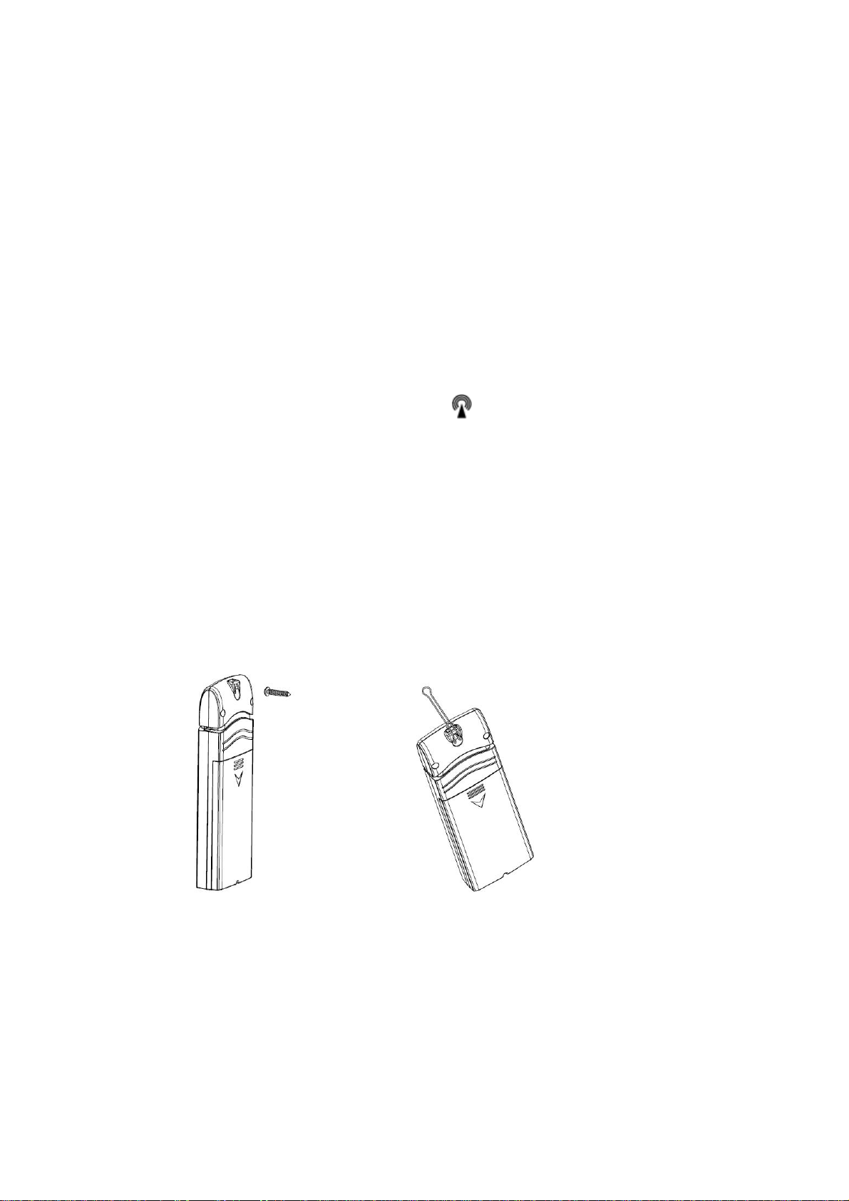
1. Use a screw or nail to affix the remote sensor to the wall, as shown in Figure 7
2. Hang the remote sensor up on string, as shown in Figure 8.
Figure 7 Figure 8
5. Program modes
5.1 Normal display Mode

Figure 9
1. Graph for Temperature/Dew point/heat index/humidity of sensors.
2. Date and time.
3. Outdoor Temperature/Dew point/heat index/humidity for channel 1 and other channels
defined to be displayed in CH1 area in turn.
4. Outdoor Temperature/Dew point/heat index/humidity for channel 2 and other channels
defined to be displayed in CH2 area in turn.
5. Outdoor Temperature/Dew point/heat index/humidity for channel 3 and other channels
defined to be displayed in CH3 area in turn.
6. Outdoor Temperature/Dew point/heat index/humidity for channel 4 and other channels
defined to be displayed in CH4 area in turn.
7. Outdoor Temperature/Dew point/heat index/humidity for channel 5 and other channels
defined to be displayed in CH4 area in turn
8. Alarm icon
9. RCC reception icon
After the console receives data from each remote sensor, user can press these 4 buttons for
operation.

Figure 10
Icon Description
Graph key
Switch to display graph of Temperature/Dew point/heat
index/humidity for all sensors
Brightness control key
Press this key to increase the brightness
Brightness control key
Press this key to decrease the brightness
Menu Key
Press this key to enter menu and scroll to different modes
5.2 Setup Mode
Under Normal mode, press MENU key once to enter Setup Mode.
Icon Description
Scroll right key
Press this key to scroll down/right. .
Selection key
Press this key to select and enter the option.

Scroll left key
Press this key to scroll up/left.
Mode key
Press this key to enter to next mode
CH Area1-5
Scroll to selected channel area, and press key to enter the setting interface as below:
Icon Description
Scroll right key
Press this key to scroll down/up. .
Selection key
Press this key to select and enter the option.
Scroll left key
Press this key to scroll right/left.
Return key
Press this key to back to Setup main menu.
Press and key, a red dot will be moving among these boxes. Each box
represents a certain channel (1-8) and parameter (Temperature, dew point, heat index).
Press key, the wanted parameter of wanted channel would be displayed on the
temperature position of channel area.

For example, press Setup Key of CH Area1 to enter the Area Section interface, you will find
temperature of channel 1 is default selected. Move the red dot to choose temperature of
channel 5, the temperature and humidity of channel 1 and channel 5 would be displayed on
CH1 Area in turn. Please note humidity data would be displayed automatically once you
select the channel.
Graph Time
This is to set length of history time for graph among 12h/24h/48h/72h.
Time Format
Select time format between AM h:mm:ss, h:mm:ss AM, h:mm:ss..
Date Format
Select date format between MM-DD-YYYY and DD-MM-YYYY
Date and time
This is to set time, date, DST, and time zone.
Temperature Units
This is to select temperature units between ℃and ℉
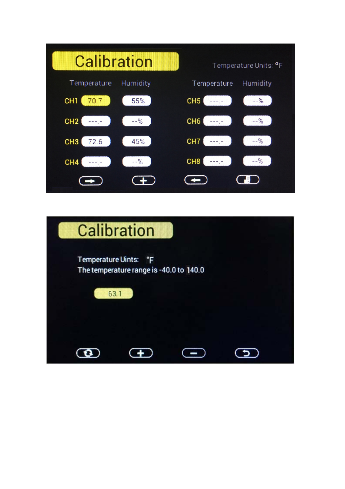
5.3 Calibration Mode
Under Normal mode, press MENU key twice to enter Calibration Mode. Users can calibrate the
temperature and humidity of indoor and outdoor sensors here.

Icon Description
Scroll down/right key
Press this key to scroll down/right. .
Selection/value increase key
Press this key to select parameter and enter the calibration
interface. Increase the value during calibration.
Value Decrease key
Decrease the value during calibration.
Resume key
Press this key to cancel the calibration and resume the data.
Scroll up/left key
Press this key to scroll up/left.
Mode key
Press this key to enter to next mode
Return Key
Back to main menu of calibration mode.
5.4 Max/Min & Alarm Mode
Under Normal mode, press MENU key three times to enter Max/Min & Alarm Mode. Users can
check max/min records of temperature, humidity, dew point, heat index of each sensor.
And high/low alarms of humidity and temperature can be configured here.

Icon Description
Scroll down/right key
Press this key to scroll down/right. .
Selection/value increase key
Press this key to select parameter to check according max/min
records. Switch on/off alarms and increase the value during alarm
setup.
Value Decrease key
Decrease the value during alarm setup.
Scroll up/left key
Press this key to scroll up/left.
Mode key
Press this key to enter to next mode
Return Key
Back to main menu of calibration mode.
Temperature Max/Min interface
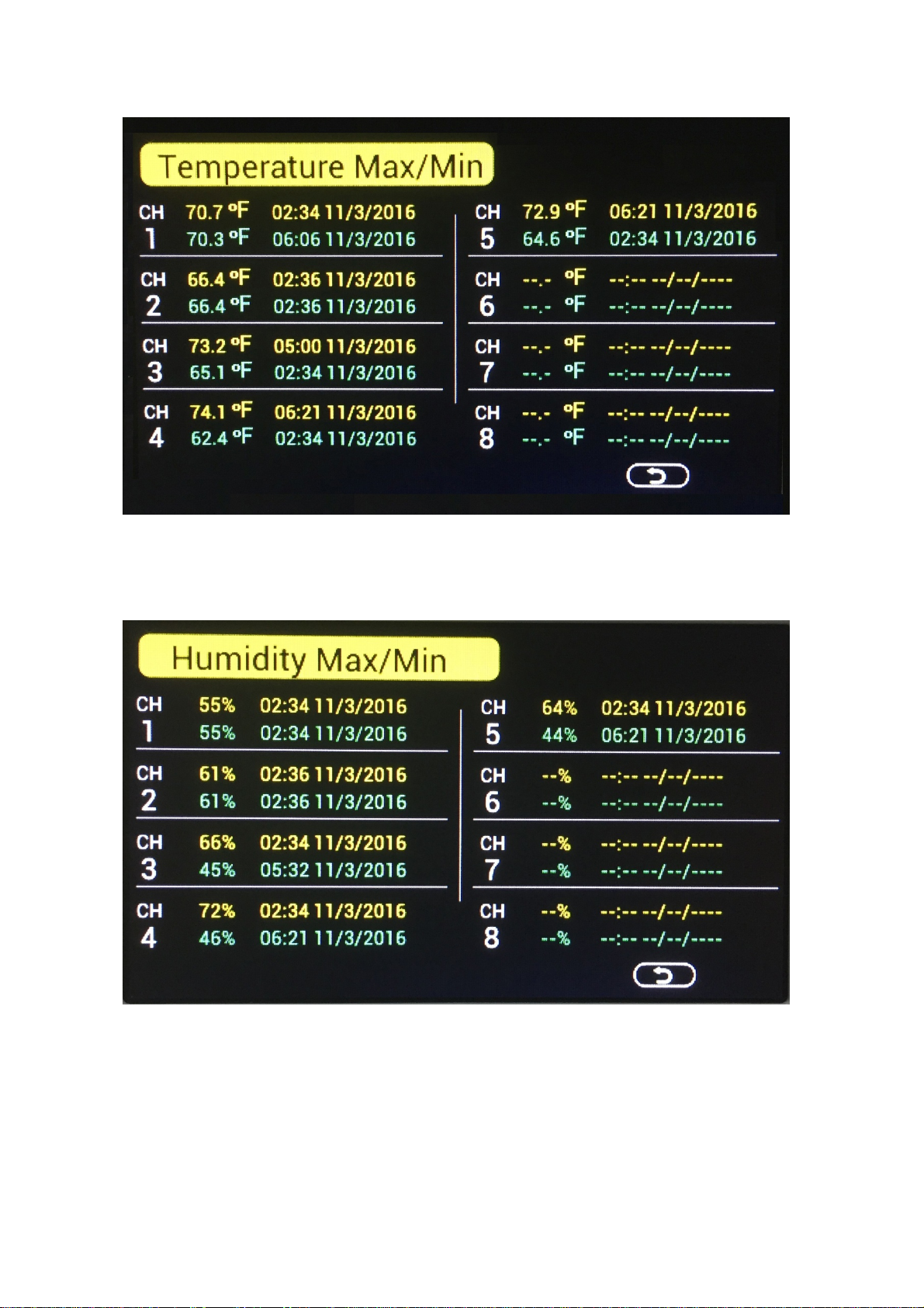
Humidity Max/Min interface
Dew point Max/Min interface

Heat index Max/Min interface
High/Low alarm of Humidity setting
To enter alarm setting interface, you need to select the alarm ON (default OFF): scroll to OFF key
before Humidity alarm, and press key to switch on the alarm. Then scroll to Humidity
alarm and press key to enter humidity alarm setting mode.

When an alarm condition has been activated, the specific alarm will sound and flash for 120
seconds, the alarm icon will turn to red color (high alarm) or blue color (low alarm).
The alarm icon will show on display console until the weather condition doesn’t meet the
user set level. Press any key to mute the alarm.
color change as below
color

High alarm Red – grey - red
Low alarm Blue – grey - blue
High alarm & Low alarm both activated Red – grey – blue – grey – red
Beep alarm stop grey
High/Low alarm of Temperature setting
To enter alarm setting interface, you need to select the alarm ON (default OFF): scroll to OFF key
before Temperature alarm, and press key to switch on the alarm. Then scroll to
Temperature alarm and press key to enter Temperature alarm setting mode.

When an alarm condition has been activated, the specific alarm will sound and flash for 120
seconds, the alarm icon will turn to red color (high alarm) or blue color (low alarm).
The alarm icon will show on display console until the weather condition doesn’t meet the
user set level. Press any key to mute the alarm.
color change as below
color
High alarm Red – grey - red
Low alarm Blue – grey - blue
High alarm & Low alarm both activated Red – grey – blue – grey – red
Beep alarm stop grey
5.5 Factory
Under Normal mode, press MENU key four times to enter factory mode.

Factory reset: To reset the device to factory initial settings.
Clear Max/Min: Clear Max/Min records of specified outdoor sensor.
Re-register sensor:If the sensor display “-- --”, please scroll to it and enter to Re-register the
sensor.
About: Check version information.

English: To switch language.
Backlight: Set the automatically on/off time spot of back light. And adjust the brightness range.
6. Specification
Transmission distance in open field : 100meter max.
Frequency : 868MHz/915MHz

Temperature measure range: : -40 to 60C
Resolution : 0.1℃
Humidity measuring range: 10% to 99%
Humidity accuracy : +/-5% under 0-45℃
Alarm duration : 120 sec
Water proof level : IPX3
Measuring interval
Outdoor sensor channel 1 : 61s
Outdoor sensor channel 2 : 62s
Outdoor sensor channel 3 : 63s
Outdoor sensor channel 4 : 69s
Outdoor sensor channel 5 : 65s
Outdoor sensor channel 6 : 66s
Outdoor sensor channel 7 : 67s
Outdoor sensor channel 8 : 68s
Powe
r
consumption
Base station : 5V DC adaptor (included)
Indoor sensor : 2xAA alkaline batteries (not included)
Remote sensor : 2xAA rechargeable batteries (not included)
Table of contents
Other Foshk Weather Station manuals


Popular Weather Station manuals by other brands


ACU-RITE
ACU-RITE 623 instruction manual

ACU-RITE
ACU-RITE 03001W instruction manual

Oregon Scientific
Oregon Scientific BAR933HG user manual

La Crosse Technology
La Crosse Technology Tomorrow's Weather Today WS-7394U-IT instruction manual

Hama
Hama 186421 operating instructions

2measure
2measure 260302 Operation manual

La Crosse Technology
La Crosse Technology WS-2813U-IT Operation manual

Oregon Scientific
Oregon Scientific BA-116 instruction manual

Oregon Scientific
Oregon Scientific EB313HGN user manual

Buienradar
Buienradar BR700 user manual

Auriol
Auriol H13726 Operation and safety notes

La Crosse Technology
La Crosse Technology WS-9077U-IT Quick setup guide