Foshk WH0260 User manual

1
WIFI CONNECTION WEATHER STATION
Operation Manual
Table of Contents
1. Introduction.....................................................................................................................................................2
2. Warnings and Cautions................................................................................................................................2
3. Quick Start Guide..........................................................................................................................................2
4. Setting Started...............................................................................................................................................2
4.1 Contents............................................................................................................................................2
4.2 Outdoor Thermo-hygrometer Sensor Set Up..............................................................................3
4.3 Best Practices for Wireless Communication............................................................................... 4
4.4 Display console................................................................................................................................4
5. Display Console Operation..........................................................................................................................5
5.1 Screen Display.................................................................................................................................5
5.2 Initial Display Console Set Up....................................................................................................... 5
5.3 Key function......................................................................................................................................6
5.4 Setting mode.................................................................................................................................... 7
5.4.1 BEEP......................................................................................................................................7
5.4.2 DST........................................................................................................................................7
5.4.3 Time zone..............................................................................................................................7
5.4.4 Time / Date............................................................................................................................7
5.4.5 Temperature..........................................................................................................................8
5.5 Alarm mode.......................................................................................................................................8
5.5.1 Display of Alarm value.........................................................................................................8
5.5.2 Alarm mode setting..............................................................................................................9
5.5.3 Alarm Setting Order.............................................................................................................9
5.6 Factory Reset/Clear Memory.........................................................................................................9
6. Specification...................................................................................................................................................9
7. WIFI connection setting on mobile...........................................................................................................10
2
1. Introduction
Thank you for your purchase of our Wireless weather station with WiFi connection. The
following user guide provides step by step instructions for installation, operation and
troubleshooting.
2. Warnings and Cautions
Warning: Any metal object may attract a lightning strike, including your weather station
mounting pole. Never install the weather station in a storm.
Warning: Installing your weather station in a high location may result in injury or death.
Perform as much of the initial check out and operation on the ground and inside a building or
home. Only install the weather station on a clear, dry day.
3. Quick Start Guide
Although the manual is comprehensive, much of the information contained may be intuitive. In
addition, the manual does not flow properly because the sections are organized by
components.
The following Quick Start Guide provides only the necessary steps to install, operate the
weather station, and upload to the internet, along with references to the pertinent sections.
Required
Step Description Section
1 Power up the outdoor thermo-hygrometer sensor 4.2
2 Power up the base station,synchronize with the outdoor sensors 5.2
Optional
4ConfigureWiFi 7
5 Register and upload to Weather Server 7
4. Setting Started
4.1 Contents
QTY Item
1 Display Console
1 Outdoor sensor
1 5V DC Adapter
1Nylon zip
2Screws
1 User manual

3
4.2 Outdoor Thermo-hygrometer Sensor Set Up
Note: To avoid permanent damage, please take note of the battery polarity before inserting the
batteries.
Remove the battery door on the back of the sensor. Insert two AA batteries.
We recommend lithium batteries for cold weather climates, but alkaline batteries are sufficient
for most climates. We do not recommend rechargeable batteries. They have lower voltages, do
not operate well at wide temperature ranges, and do not last as long, resulting in poorer
reception.
Replace the battery door. Note that the temperature and humidity will be displayed on the LCD
display. Looking at the back of the unit from left to right, the polarity is (-) (+) for the top battery
and (+) (-) for the bottom battery.
Note: the humidity is only displayed on outdoor thermo-hygrometer sensor

4
4.3 Best Practices for Wireless Communication
Note: To insure proper communication, mount the remote sensor(s) upright on a vertical
surface, such as a wall. Do not lay the sensor flat.
Wireless communication is susceptible to interference, distance, walls and metal barriers. We
recommend the following best practices for trouble free wireless communication.
1. Electro-Magnetic Interference (EMI). Keep the console several feet away from
computer monitors and TVs.
2. Radio Frequency Interference (RFI). If you have other 433 MHz devices and
communication is intermittent, try turning off these other devices for troubleshooting
purposes. You may need to relocate the transmitters or receivers to avoid intermittent
communication.
3. Line of Sight Rating. This device is rated at 300 feet line of sight (no interference,
barriers or walls) but typically you will get 100 feet maximum under most real-world
installations, which include passing through barriers or walls.
4. Metal Barriers. Radio frequency will not pass through metal barriers such as aluminum
siding. If you have metal siding, align the remote and console through a window to get a
clear line of sight.
The following is a table of reception loss vs. the transmission medium. Each “wall” or
obstruction decreases the transmission range by the factor shown below.
Medium RF Signal Strength Reduction
Glass (untreated) 5-15%
Plastics 10-15%
Wood 10-40%
Brick 10-40%
Concrete 40-80%
Metal 90-100%
4.4 Display console
5
1. Insert the 5V DC adaptor into the back of the display console
Note: Place the outdoor sensor array about 5 to 10 feet from the display console and wait
several minutes for the remote sensors to synchronize with the display console.
2. Insert 2AAA batteries into the display console (optional).
3. Keep both sensor and the display console together for 3 minutes to lock in the sensor
signals.
4. After 3 minutes, follow the mounting instructions for proper placement of sensors.
Note: Your display console should have readings in all sections.
Note: If you only use battery to power up display console, you must press LIGHT/SNOOZE key
to light up the LCD before press any other key.
5. Display Console Operation
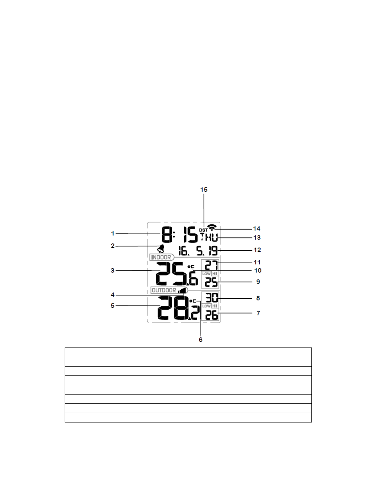
5.1 Screen Display
1.Time 9. Low indoor temperature
2. Alarm icon 10. Hi indoor temperature
3. Indoor temperature 11. Indoor temperature unit (C/F)
4. RF icon 12. Date
5. Outdoor temperature 13. Week
6. Outdoor temperature unit (C/F) 14. WIFI icon
7. Low outdoor temperature 15. DST
8. Hi outdoor temperature
5.2 Initial Display Console Set Up

6
Connect the power adapter to power up the display console.
The unit will show software version number 2 seconds after power reset.
The unit will turn on all segments of the LCD for 3 seconds after power reset, the unit will
start to register the outdoor channel for 3 minutes.
5.3 Key function
The console has 5 keys for easy operation:
Key Description
SET Press and hold the SET button 2s enter setting mode.
+/Reset-MAX Press the +/Reset-MAX button 5s, will reset high indoor/outdoor
temperature.
-/Reset-MIN Press the +/Reset-MIN button 5s, will reset low indoor/outdoor
temperature.
ALARM Press and release the ALARM button to enter alarm mode.
Press and hold the ALARM button 2s to enter alarm setting mode.
LIGHT/SNOOZE Press and release LIGHT/SNOOZE button open the back light 5s.
Note:
1) When DC power supply is insert, press and hold the LIGHT/SNOOZE button 2s to keep
the back light always on, of course user can press and hold the LIGHT/SNOOZE button
2s to disable this function.
2) When in time alarming, press LIGHT/SNOOZE button enter snooze mode.
3) Press the +/Reset-MAX and -/Reset-MIN button 5s, will unlock present transmitter and
search a new device in the next 3 minutes.
7
4) Press the SET and ALARM button 5s, will set WIFI module enter into Smart
Configuration Mode.
5) Once every 10 minutes record a temperature, record 144 times, calculation of the
maximum and minimum values.
5.4 Setting mode
Pressing the SET key for 2 seconds to enter setting model,the basic settings can now be
performed in the following order:
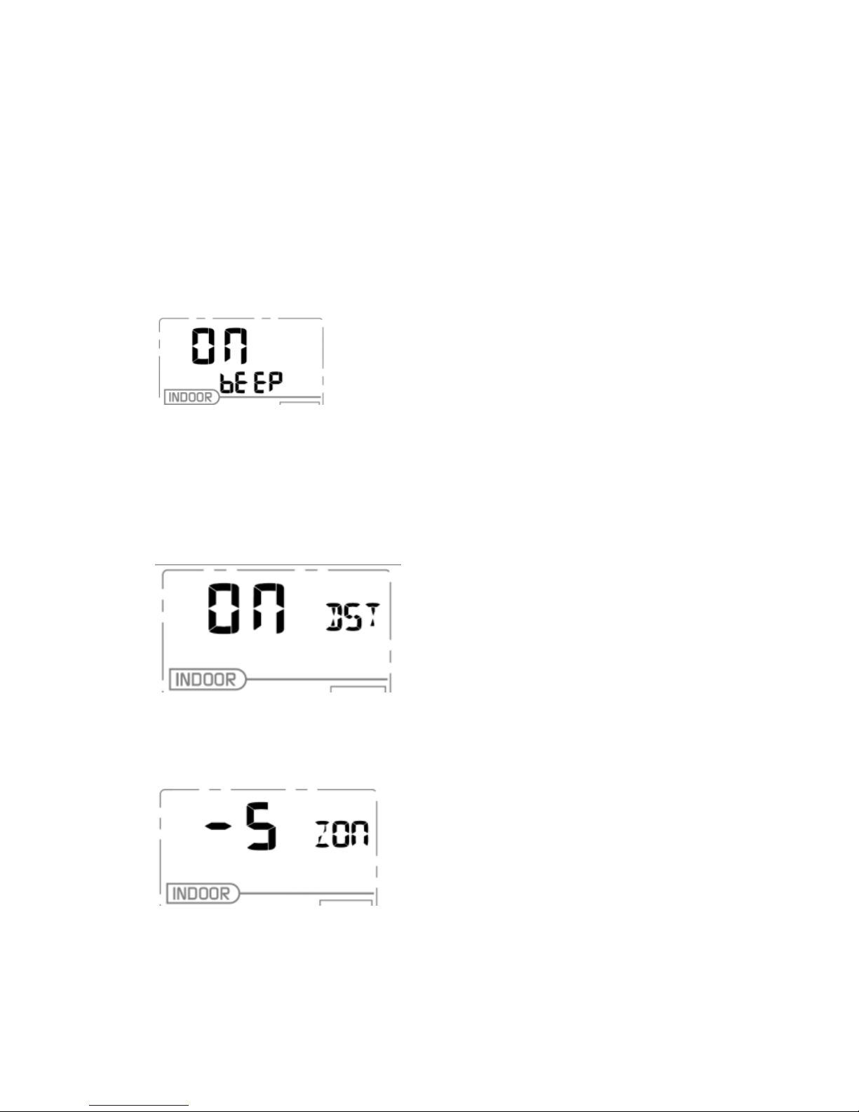
5.4.1 BEEP
-PresstheSET key for 2 seconds to select the beep section, ON/OFF section digits will
start flashing, press the +/Reset-MAX and -/Reset-MIN button to select ON or OFF.
“BEEP ON” will make the Beep sound on every key press. If you do not want the beep
sound to be heard, select “BEEP OFF”
5.4.2 DST
-PresstheSET key for 2nd time to select the DST section, ON/OFF section digits will start
flashing, press the +/Reset-MAX and -/Reset-MIN button to select ON or OFF.
5.4.3 Time zone
-PresstheSET key 3rd time to select the Time zone section, time zone section digits will
start flashing,press the +/Reset-MAX and -/Reset-MIN button to select the value . (level: -12
to +12,default: 1)
5.4.4 Time / Date

8
-PresstheSET key 4th time to select the 12/24 hour format section (default: 24hr).
-PresstheSET key 5th time to select the hour section.
-PresstheSET key 6th time to select the minutes section.
-PresstheSET key 7th time to select YY-MM-DD or MM-DD-YY format. (Default
YY-MM-DD format)
-PresstheSET key 8th time to select year.
-PresstheSET key 9th time to select month.
-PresstheSET key again time to select day.
5.4.5 Temperature
-PresstheSET key 11th to select in/outdoor temperature unit ( C or F;default: C).
Note: Press the +/Reset-MAX and -/Reset-MIN button to select the unit or scrolls the value.
Note: Press and holding the +/Reset-MAX and -/Reset-MIN button for 2 second will
increase/decrease digits in great steps.
Note: If user to change minute value, second will auto clear to 0.
Note: Press LIGHT/SNOOZE button or key idle 30 second at any time, will return to normal
mode.
Note: every 64 second the unit will measure indoor/outdoor temperature, outdoor humidity. If
temperature is to lower than minimum range, will display the minimum range -9.9˚Cor-40˚C, if
it is higher than highest range, will display the highest range 60˚C.
5.5 Alarm mode
5.5.1 Display of Alarm value
Press and release ALARM key to display alarm value

9
5.5.2 Alarm mode setting
- Press and hold ALARM button 2S enter alarm setting mode:
-Pressthe+/Reset-MAX or -/Reset-MIN buttons to adjust alert values.
-PresstheSET button to confirm & move to the next item.
-PresstheALARM button to on/off the alarm
Note: When alert is triggered, the current triggering source “ ” icon will be flashing,
indicating alert is triggered.
Note: Press LIGHT/SNOOZE button or key idle 30 second at any time, will return to normal
mode.
5.5.3 Alarm Setting Order
a)Time alarm hour setting
b)Time alarm minute setting
5.6 Factory Reset/Clear Memory
When power on, press SET button reset to default and to skip receive RF signal.
6. Specification:
Outdoo
r
data
Transmission distance in open field : 100m(330 feet)
Frequency : 433MHz/868MHz/915 MHz
Temperature range : -40˚C--60˚C(14℉to + 140℉)
Accuracy : + / - 1˚C
Resolution : 0.1˚C
Humidity : 1 0 to 99%
Accuracy : ± 5% (only guaranteed between 20 to 90%)
Resolution : 1 %

10
Measuring interval outdoor sensor : 64 sec
Note: the humidity is only displayed on outdoor thermo-hygrometer sensor
Indoo
r
data
Indoor temperature range : -9.9˚C--60˚C(14℉to + 140℉) (show --- if outside
range)
Resolution : 0.1˚C
Measuring interval indoor sensor : 64 sec
Alarm duration : 120 sec
Powe
r
consumption
Base station : 5V DC adaptor (included)
or 2xAAA alkaline batteries (not included)
Remote sensor : 2xAA alkaline batteries (not included)
7. WIFI connection setting on mobile
When connect to WIFI, not measuring the indoor temperature, and receive the indoor
transmitter replace it.
If connect WIFI module, must power by DC, otherwise the WIFI not work.
WIFI only support upload the current data to weather server and time will be Internet time.
Weather server:
This station sends data to three free hosting services:
Hosting Service Website Description
Weather
Undergound WeatherUndeground.com Weather Underground is a free weather
hosting service that allows you to send
and view your weather station data
real-time, view graphs and gauges, import
text data for more detailed analysis and
use iPhone, iPad and Android
applications available at
Wunderground.com. Weather
Underground is a subsidiary of The
Weather Channel and IBM.
WeatherBug
Community backyard.weatherbug.com WeatherBug Community is an extension
of the WeatherBug community of weather
stations. WeatherBug is a brand owned
by Earth Networks that provides live
weather data and maintains a mesoscale
network of over 8,000 weather stations.
Weather Cloud WeatherCloud.net Weathercloud is a real-time weather
social network formed by observers from
around the world.
11
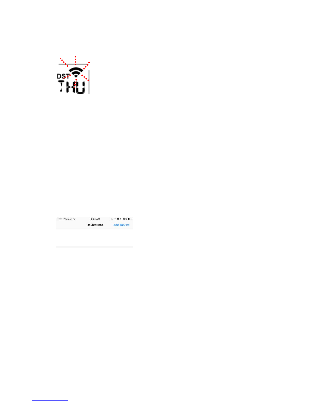
When customer first power up the device, display is in factory default mode, which will force wifi
entering auto configuring mode: the wifi icon will flash rapidly indicating wifi has not been
connected to any router before.
If device has been setup for wifi being connected to router, a manual wifi provisioning process
need to be enabled. To enabling wifi provisioning process manually, please do this:
press “set” and “Alarm“ button at the same time for 4s, display will force wifi module on board
entering auto configuring mode: the wifi icon will start flashing rapidly, indicating that WIFI
provisioning process will start again.
Steps
1. Start APP on your mobile device: WS Tool.
Noted: make sure the wifi is working on phone
Note:please download the APPs from the APP store on your smart phone before you start the
APPs
2. Press “Add Device” button to start adding a new display device to your router.
3. Enter router password.

12
Noted: Router SSID is always same as your mobile device that is being connected to router.
Press “Save”key after enter password and the information of device will be displayed
4. Touch this information label area to start WU

13
8. Registering with WeatherUnderground.com, WeatherBug.com
and WeatherCloud.net
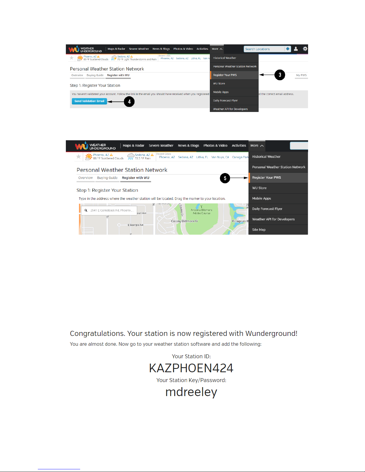
8.1 WeatherUnderground.com
Visit Wunderground.com and select the Join link at the top of the page. Select the Free sign up
option.
1. Select More | Register Your PWS.
2. Click Send Validation Email. Respond to the validation email from Wunderground (it may
take a few minutes).
14
3. Select More | Register Your PWS again and enter all of the information requested.
4. After registering your station, make a note of the following:
•Station ID
•Station Key / Password
Enter the Station ID (ID), Station Key (Password) and Station Number (StationNum) into the Ambient
Tool. Leave the StationNum field blank.
Figure 34 is an example, and your station ID and password will be different.
Note: Your station ID will have the form: KSSCCCC###, where K is for USA station (I for
international), SS is your state, CCCC is your city and ### is the station number in that city.

15
In the example above, KAZPHOEN424 is in the USA (K), State of Arizona (AZ), City of Phoenix
(PHOEN) and #424.
8.2 WeatherBug.com
Visit http://pws.ensb.us/ and Click here to register your station.
After registering your station, make a note of the following:
•UserName
•Password
•Your Publisher ID
•Your Station Number
Enter the Publisher ID (ID), Password and Station Number (StationNum) into the Ambient Tool.
16
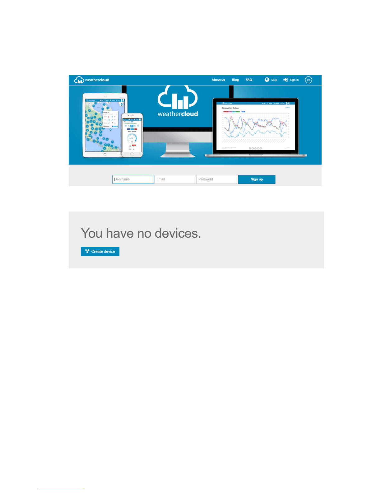
8.3 WeatherCloud
1. Visit WeatherCloud.net and enter a Username, Email and Password.
2. Respond to the validation email from WeatherCloud (it may take a few minutes).
3. Select Create Device and enter your weather station information. After registering your
station, make a note of the following:
•Weathercloud ID
•Key
Enter the Weathercloud ID (ID), Key (password) into the Ambient Tool. Leave the Station Number
(StationNum) blank.
Table of contents
Other Foshk Weather Station manuals


Popular Weather Station manuals by other brands


Logia
Logia LOWSC710SWB user guide

La Crosse Technology
La Crosse Technology WS-2800 instruction manual

La Crosse Technology
La Crosse Technology WS-9005 Instructional manual

Oregon Scientific
Oregon Scientific BARM688 user manual

Gewiss
Gewiss Chorus GW90800 manual

Eurochron
Eurochron EPT-D1 operating instructions


