Foshk WH2900 User manual

PROFESSIONAL WEATHER STATION
Operation Manual
Table of Contents
1. Introduction......................................................................................2
2. Warnings and Cautions...................................................................3
3. Quick Start Guide............................................................................3
4. Pre-Installation Checkout and Site Survey......................................4
4.1 Pre Installation Checkout.............................................................4
4.2 Site Survey..................................................................................4
5. Setting Started ................................................................................5
5.1 Contents......................................................................................5
5.2 Sensor Set Up .............................................................................6
5.2.1. Install U-bolts and mounting pole.........................................6
5.2.2. Install wind vane...................................................................7
5.2.3. Install wind speed.................................................................8
5.2.5. Mount assembled outdoor sensor package .........................9
5.2.5.1 Before you mount .............................................9
5.2.5.2 Mounting.........................................................10
5.2.6 Reset Button and Transmitter LED......................................11
5.3 Best Practices for Wireless Communication..............................11
5.4 Display console..........................................................................12
5.4.1 Vertical Desk Stand.............................................................13
6. Display Console Operation............................................................14
6.1. Screen Display..........................................................................14
6.2. Initial Display Console Set Up ..................................................15
6.3 Key function...............................................................................15
6.4 Setting mode .............................................................................17
6.4.1 BEEP: .................................................................................17
6.4.2 MAX/MIN Daily:...................................................................17
6.4.3 DST(daylight saving time):..................................................17
6.4.4 Time zone............................................................................18
6.4.5 Time / Date..........................................................................18
6.4.6 Pressure..............................................................................19
6.4.7 Light....................................................................................20
6.4.8 Temperature........................................................................20
6.4.9 Wind speed.........................................................................21
6.4.10 Rain...................................................................................21
1

6.4.11 Moon phase.......................................................................22
6.5 Alarm mode ...............................................................................22
6.5.1 Display of Alarm value.........................................................22
6.5.2 Alarm mode setting: ............................................................23
6.5.3 Alarm Setting Order:............................................................23
6.6 Max/min mode...........................................................................24
6.6.1 Press and release MAX/MIN key to display MAX data........24
6.7 Calibration mode........................................................................24
6.8 Other Features...........................................................................25
6.8.1 Factory Reset/Clear Memory ..............................................25
6.8.2 Register New Transmitter....................................................26
6.8.3 Backlight Operation.............................................................26
6.8.4 Tendency indicators ............................................................26
6.8.5 Wireless Signal Strength Indicator......................................27
6.8.6 Weather forecast.................................................................27
6.8.7 Snooze................................................................................29
7. Specification:.................................................................................29
8. Live Internet Publishing.................................................................30
8.1 Connecting the Weather Station Console to WiFi......................31
8.1.1 Download mobile application...............................................31
8.1.2 Connect the console to Wi-Fi..............................................31
8.1.2.1 Android user:...................................................31
8.1.2.2 iOs user: .........................................................39
8.2 Mobile application – Device list..................................................45
8.3 Mobile application – Check WU weather data and graph..........46
8.4 Mobile application – Remove or Add WU ID..............................47
8.5 Mobile application – Set Units ...................................................48
9. Registering WeatherUnderground.com through the PC or Mac....50
10. Maintenance................................................................................54
11. Troubleshooting Guide ................................................................58
1. Introduction
Thank you for your purchase of the Solar Powered Wireless WiFi
Weather Station. The following user guide provides step by step
instructions for installation, operation and troubleshooting.
2

2. Warnings and Cautions
Warning: Any metal object may attract a lightning strike, including
your weather station mounting pole. Never install the weather station
in a storm.
Warning: Installing your weather station in a high location may
result in injury or death. Perform as much of the initial check out and
operation on the ground and inside a building or home. Only install the
weather station on a clear, dry day.
3. Quick Start Guide
Although the manual is comprehensive, much of the information
contained may be intuitive. In addition, the manual does not flow
properly because the sections are organized by components.
The following Quick Start Guide provides only the necessary steps to
install, operate the weather station, and upload to the internet, along
with references to the pertinent sections.
3
Required
Step Description Section
1 Assemble and power up the Y shape sensor 5.2.1–5.2.3
2 Power up the display console and synchronize
with Y shape sensor 5.4
5 Mount the sensor array 5.2.4
3 Set date and time on console 6.4.5
4 Calibrate the relative pressure to sea-level
conditions (local airport) on console 6.7.1
6 Reset the rain to zero on console 6.4.10
Optional
7 Configure WiFi 8.1
8 Register and upload to Weather Server 9
4. Pre-Installation Checkout and Site Survey
4.1 Pre Installation Checkout
Before installing your weather station in the permanent location, we
recommend operating the weather station for one week in a temporary
location with easy access. This will allow you to check out all of the
functions, insure proper operation, and familiarize you with the weather
station and calibration procedures. This will also allow you to test the
wireless range of the weather station.
4.2 Site Survey
Perform a site survey before installing the weather station. Consider the
following:
1. You must clean the rain gauge every few months and change
the rechargeable batteries every 2-3 years. Provide easy
access to the weather station.
2. Avoid radiant heat transfer from buildings and structures. In
general, install the sensor array at least 5’ from any building,
structure, ground, or roof top.
3. Avoid wind and rain obstructions. The rule of thumb is to install
the sensor array at least four times the distance of the height of
the tallest obstruction. For example, if the building is 20’ tall, and
the mounting pole is 6’ tall, install 4 x (20 – 6)’ = 56’ away.
4

4. Wireless Range. The radio communication between receiver
and transmitter in an open field can reach a distance of up to
100meter, providing there are no interfering obstacles such as
buildings, trees, vehicles, high voltage lines. Wireless signals
will not penetrate metal buildings. Under most conditions, the
maximum wireless range is 100’.
5. Radio interference such as PCs, radios or TV sets can, in the
worst case, entirely cut off radio communication. Please take
this into consideration when choosing console or mounting
locations. Make sure your display console is at least five feet
away from any electronic device to avoid interference.
5. Setting Started
5.1 Contents
QTY Item
1 Display Console
1 Y shape outdoor sensor(Thermo-hygrometer / Rain Gauge /
Wind Speed Sensor /Transmitter)
1 Wind Vane
1 5V DC Adapter
1 U-bolt with mounting clamps
1 User manual
1 Zip bag for 1pc 10mm single-head wrench
5

5.2 Sensor Set Up
1. Wind Vane
2. Wind Speed Sensor
3. UV sensor/ Light sensor
4. Thermo-hygro sensor
5. Rain collector
6. Bubble level
7. Solar panel
8. U-Bolt partment
r 4s if the unit power up. Then the LED will
ds (the sensor transmission update period).
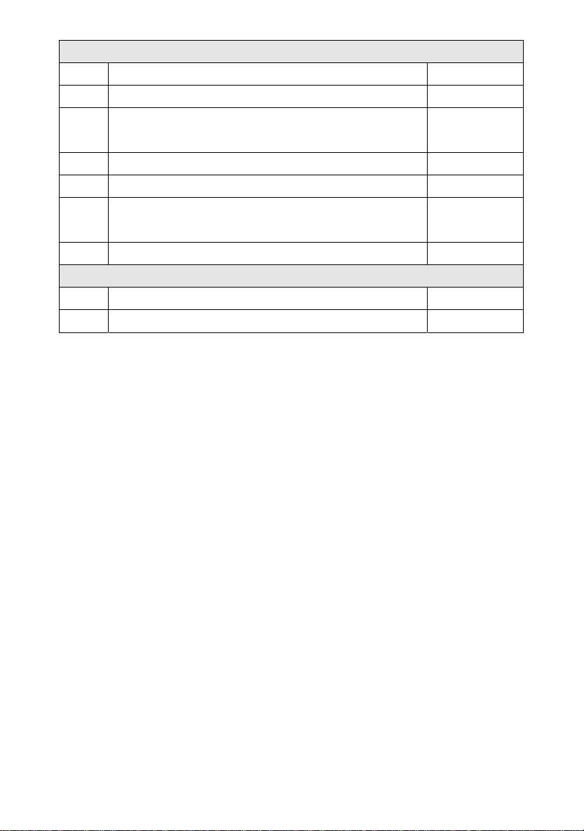
bolts and mounting pole
he U-bolts, which are in turn used to mount the sensor
n a pole, requires installation of an included metal plate to
The metal plate, visible in Figure 1, has four
ch the ends of the two U-Bolts will fit. The plate itself is
urved profile (which will end up “hugging” the mounting pole). Once the
e U-Bolts and insert both
9. Battery com
10. Reset button
11. LED Indicator: light on fo
flash once every 16 secon
5.2.1. Install U-
Installation
package o of t
receive the U-bolt ends.
holes through whi
inserted in a groove on the bottom of the unit (opposite side of solar
panel). Note that one side of the plate has a straight edge (which goes
to the groove), the other side is bent at a 90-degree angle and has ain
c
metal plate is inserted, remove nuts from th
U-bolts through the respective holes of the metal plate as shown in
Figure 8.
6
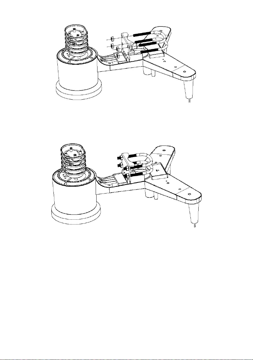
Loosely screw on the nuts on the ends of the U-bolts. You will tighten
these later during final mounting. Final assembly is shown in Figure 9.
The plate and U-Bolts are not yet needed at this stage but doing this
now may help avoid damaging wind vane and wind speed cups later on.
5.2.2. Install wind vane
Push the wind vane onto the shaft on the top of the sensor, unitl it goes
further, as shown in figure 3.
ighten the set screw, with a Phi river(size PH0), until the
easurements.
Figure 1
Figure 2
lips screwdT
wind van cannot be removed from the axle, as shown in figure 4. Make
sure the wind vane spin freely. The wind vane’s movement has a small
amount of friction, which is helpful in providing steady wind direction
m
7

Figure3 Figure4
There are four alphabet letter of “N”,”E”,”S”and “W” around the wind
direction, representing for the direction of North, East, South and West.
Wind direction sensor has to be adjusted so that the directions on the
sensor are matching with your real location. Permanent wind direction
error will be introduced when the wind direction sensor is not positioned
correctly during installation.
.2.3. Install wind speed
Figure5 Figure6
5.2.4. Install Batteries
5
Push the wind speed into the shaft. as shown in figure 5.
Tighten the set screw with as shown in figure 5. Make sure the wind
speed spin freely.
8

Insert 2XAA batteries in the battery compartment. The LED indicator on
the back of the transmitter will turn on for four seconds and normally
flash once every 16 seconds (the sensor transmission update period).
Figure7 Figure8
ll
sensor
Note: We recommend lithium batteries for cold weather climates, but
alkaline batteries are sufficient for most climates. We do not
recommend rechargeable batteries. They have lower voltages, do not
operate well at wide temperature ranges, and do not last as long,
resulting in poorer reception.
5.2.5. Mount assembled outdoor sensor package
5.2.5.1 Before you mount
section,
ou may want to skip to setup instructions in section 6.2 and onwards
tup is complete and everything is working, return here for
Note: If no LED light up or is lighted permanently, make sure the battery
is inserted the correct way or a proper reset is happened. Do not insta
the batteries backwards. You can permanently damage the outdoor
Before proceeding with the outdoor mounting detailed in this
y
first, while you keep the assembled outdoor sensor package nearby
(although preferably not closer than 5 ft. from the console). This will
make any troubleshooting and adjustments easier and avoids any
distance or interference related issues from the setup.
fter seA
outdoor mounting. If issues show up after outdoor mounting they are
almost certainly related to distance, obstacles etc.
9
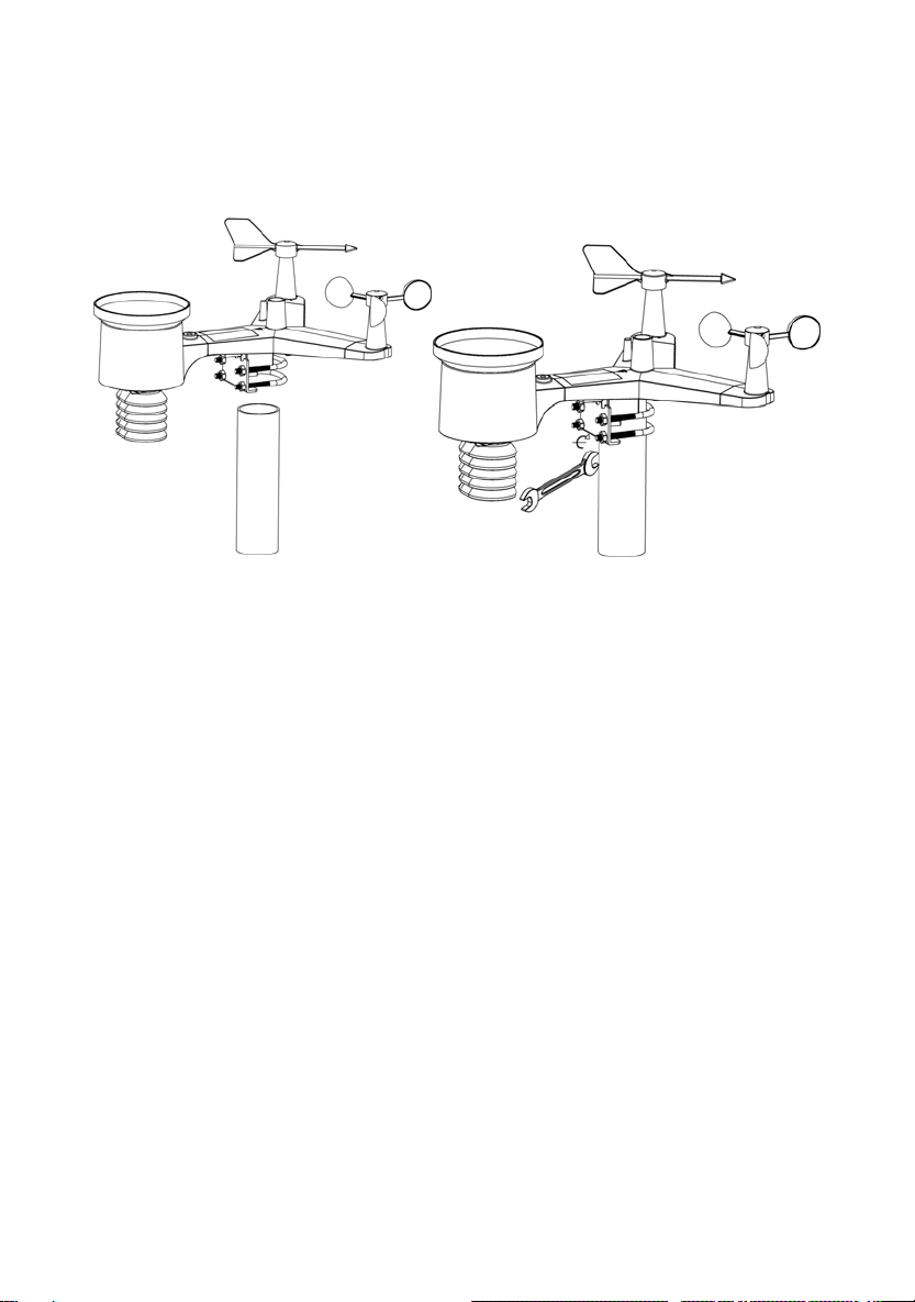
5.2.5.2 Mounting
You can attach a pipe to a permanent structure and then attach the
Figure 9). The U-Bolts will accommodate a
Finally, place the sensor package on top of the prepared mounting pipe.
The U-Bolts should be loose enough to allow this but loosen the nuts as
necessary. Once placed, hand tightens all four nuts, taking care to do
so evenly.
Now you will need to align the whole package in the proper direction by
rotating it on top of the mounting pipe as needed.
Locate the arrow
labeled “North” that you will find on top of the sensor package right
next to the light sensor. You must rotate the whole sensor package
until this arrow points due north. To achieve proper alignment, it is
helpful to use a compass (many cell phones have a compass
application). Once rotated in the correct orientation, lightly tighten the
bolts a little more (use a wrench) to prevent further rotation.
Note: Use the bubble level next to the rain sensor to make sure sensor
array is completely level.If the sensor is not level,the rain gauge,UV and
solar radiation sensors will not measure properly.
sensor package to it (see
pipe diameter of 1-2 inches (pipe not included).
Figure 10
10

5.2.6 Reset Button and Transmitter LED
In the event the sensor array is not transmitting, reset the sensor array.
With an open ended paperclip, press and hold the RESET BUTTON for
three seconds to completely discharge the voltage.
Figure 11
.
lectro-Magnetic Interference (EMI). Keep the console several feet
communication.
rated at 300 feet line of
100 feet maximum under most real-world installations, which
s through metal
5.3 Best Practices for Wireless Communication
Note: To insure proper communication, mount the remote sensor(s)
upright on a vertical surface, such as a wall. Do not lay the sensor flat
Wireless communication is susceptible to interference, distance, walls
and metal barriers. We recommend the following best practices for
trouble free wireless communication.
E
away from computer monitors and TVs.
Radio Frequency Interference (RFI). If you have other 433 MHz
devices and communication is intermittent, try turning off these other
ices for troubleshooting purposes. You may need to relocate thedev
transmitters or receivers to avoid intermittent
1. Line of Sight Rating. This device is
sight (no interference, barriers or walls) but typically you will get
include passing through barriers or walls.
2. Metal Barriers. Radio frequency will not pas
11

barriers such as aluminum siding. If you have metal siding, align
the remote and console through a window to get a clear line of
sight.
The following is a table of reception loss vs. the transmission
medium. Each “wall” or obstruction decreases the transmission
range by the factor shown below.
Medium RF Signal Strength Reduction
Glass (untreated) 5-15%
Plastics 10-15%
Wood 10-40%
Brick 10-40%
Concrete 40-80%
Metal 90-100%
5.4 Display console
1. Insert the 5V AC adaptor into the back of the display console
Note: Place the outdoor sensor array about 5 to 10 feet from the display
console and wait several minutes for the remote sensors to synchronize
with the display console.
2. Insert 3 AAA batteries into the display console。Please insert the
battery as blew figure 12:
Figure 12
12

Note: T s are intend
backlight will remain on for 5 seconds whe ck up battery
power only. Only when you use power a light
be continuously on.
3. Keep both sensor and the display console together for 15 minutes
to lock in the sensor signals.
. Spin the wind cups to simulate wind speed. Take the sensor to the
r into the rain bucket to simulate rain.
w the mounting instructions for proper
Figure 13
Note: Your display console should have readings in all sections. Wind
and Rain will show 0’s (connected) until wind or rain occur or are
simulated.
Note: If you only use battery to power up display console, you must
press LIGHT/SNOOZE key to light up the LCD before press any other
key.
5.4.1 V
The
In a
the console also includes a vertical desk stand to improve the viewing
able on a desk, as shown in Figure 14.
he batterie ed for back-up power only. The
n on ba
dapter it will the back-
4sink and slowly drip wate
5. After 15miuntes, follo
placement of sensors.
ertical Desk Stand
console is best viewed above from a 20 to 30 degree angle.
ddition to the fold out desk stand on the back of the display, console,
13
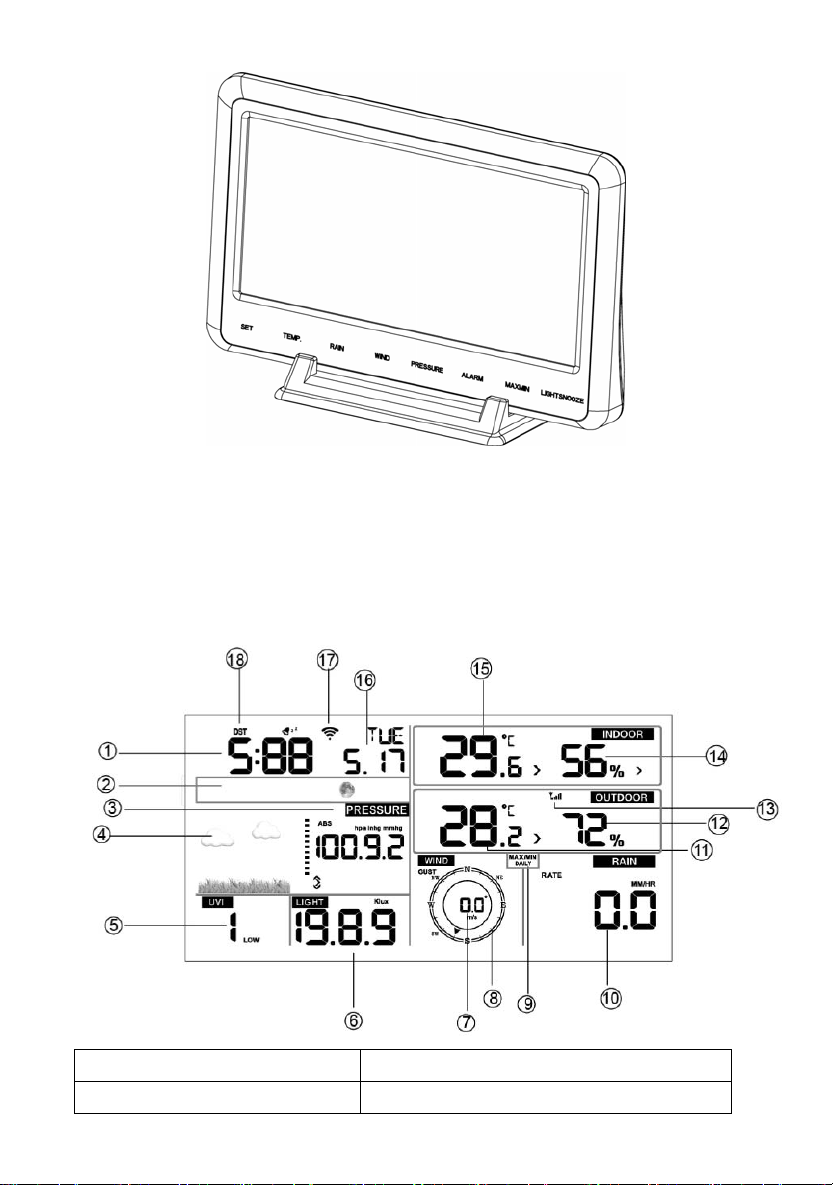
Figure 14
6. Display Console Operation
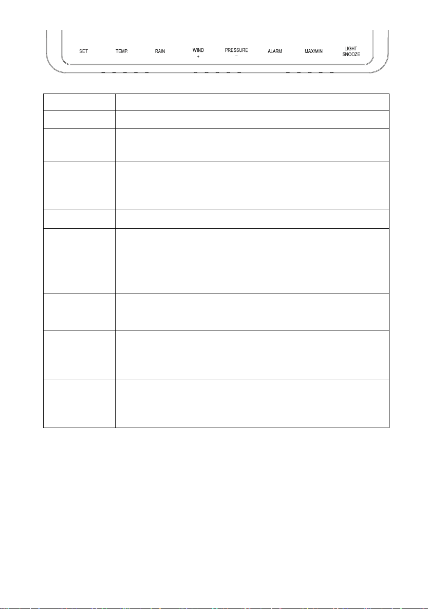
6.1. Screen Display
1.Time 10. Rain fall
2. Moon phase 11. Outdoor temperature
14
3. Barometric Pressure 12. Outdoor humidity
4. Weather forecast 13. RF icon
5. UV index 14. Indoor humidity
6. Light 15. Indoor temperature
7. Wind speed 16. Date
8. Wind direction 17. WIFI icon
9. MAX/MIN Daily 18. DST
6.2. Initial Display Console Set Up
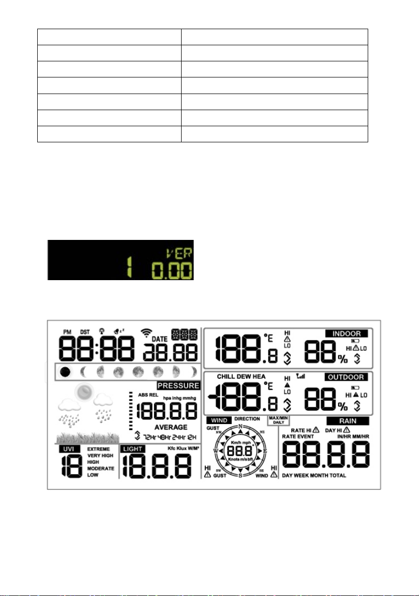
Connect the power adapter to power up the display console.
The unit will show software version number 2 seconds after power
reset.
e LCD for 3 seconds after power
reset, the unit will start to register the outdoor channel for 3 minutes.
function
eight keys for
The unit will turn on all segments of th
6.3 Key
The console has easy operation
15
Key Description
SET Hold this key to enter setting mode
TEMP. Press this key to view wind Chill, Heat Index, Dew
Point Temperature
RAIN Press this key to view Rain Rate, event, Rain Day
Rain Week, Rain Month, and Rain total ,
Press the RAIN key 2s to reset current display rain
WIND + Press this key to view wind/gust and wind direction
PRESSURE Press this key to view Absolute Pressure average of
12hr, 24hr, 48hr and 72hr
Press and hold 2s this key to view the absolute and
relative pressure
ALARM Press this key to view the alarm value of Temperature /
Humidity/rain rate/rain day/wind
MAX/MIN Press this key to view the MAX/MIN value of
Temperature / Humidity/rain rate/rain
day/wind/UVI/LIGHT/Absolute Pressure
LIGHT
/SNOOZE Press this key to adjust LCD backlight brightness:
HI/MID/OFF
Hold this key to register new transmitter
Note:
1) When power on, press WIND/+ and PRESSURE /- key to reset the
weather station and clear all records memory, and clears all user
settings to default.
2) When power on, press TEMP. key to skip receive RF signal.
pressing WIND/+ or PRESSURE/- key select the
ess and holding WIND/+ or
e/decrease digits in
great steps.
4) The setting procedure can be exited at any time by either pressing
the LIGHT /SNOOZE key or waiting for the 30-second time-out to
3) In Setting mode,
unit or scrolls the value; keeping pr
PRESSURE/- key for 2 second will increas
16

take effect.
6.4 Setting mode
ssing the SET key for 2 seconds to enter setting model,the basic
settin now be performed in the following order:
6.4.1 BEEP:
- Press the SET tion, ON/OFF
section digits wi
k ct ON
“ l ot
want the beep s EEP OFF”
6.4.2 MAX/MIN
- Press the SET ction,
O section
PRESSURE/- k N or OFF . (Default is ON,ON: clear at
0:00 every day).
or
to select ON or OFF . (default ON, only WWVB)
Pre gs can
key for 2 seconds to select the beep sec
ll start flashing, press the WIND/+ or PRESSURE/-
ey to sele or OFF.
BEEP ON” wil make the Beep sound on every key press. If you do n
ound to be heard, select “B
Daily:
key twice to select the MAX/MIN Daily se
N/OFF digits will start flashing,press the WIND/+ or
ey to select O
6.4.3 DST(daylight saving time):
- Press the SET key third time to select the Daylight saving time
section, ON/OFF section digits will start flashing,press the WIND/+
PRESSURE/- key
Note: DST time start at 1:00am GMT of the last Sunday in March and
17
end at 1:00am GMT of the last Sunday in October.
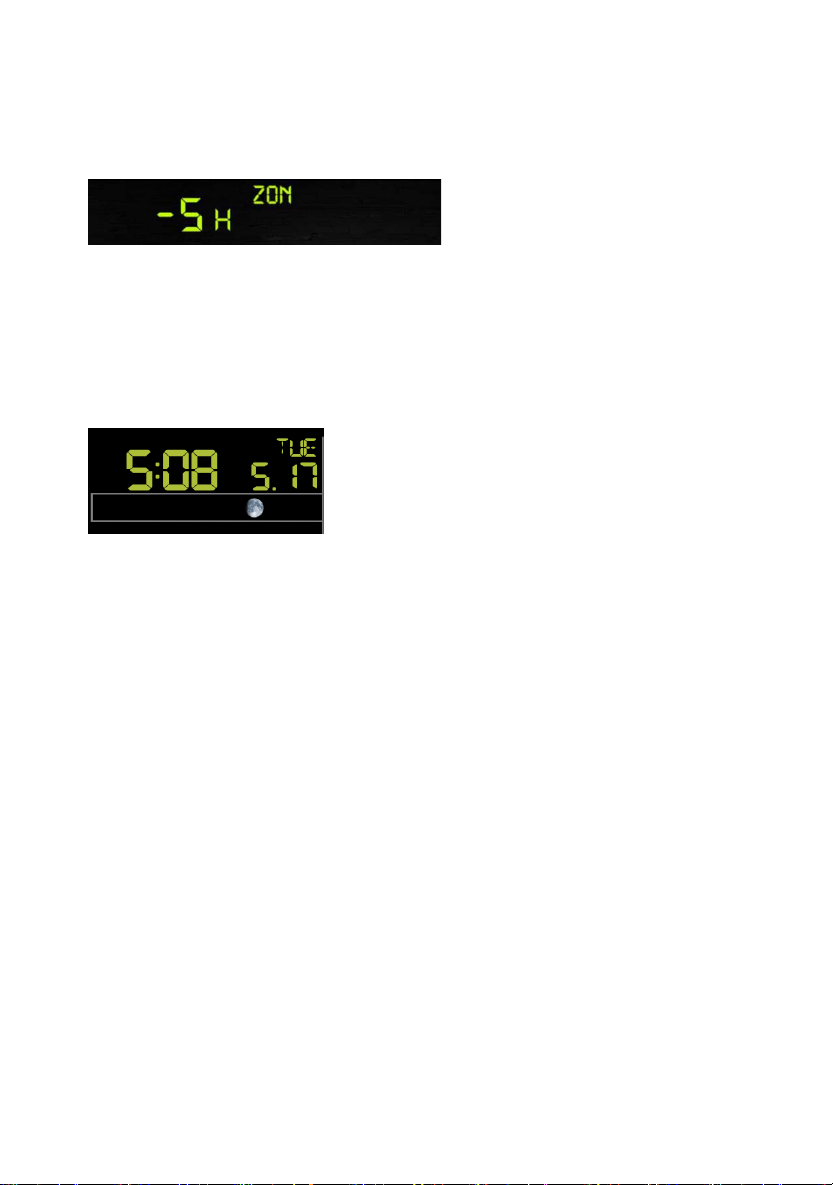
T key forth time to select the Time zone section, time
zone section digits will start flashing,press the WIND/+ or
PRESSURE/- key to selec e value . (level: -12 to +12,default: -5)
time to select the 12/24 hour format section
(default: 24hr).
- Press the SET key sixth time to select the hour section.
- Press the SET key seventh time to select the minutes section.
- Press the SET key eighth time to select DD-MM or MM-DD format.
(Default DD-MM format)
ange minute value, second will auto clear to 0.
will be updated to internet time
automatically.
6.4.4 Time zone
- Press the SE
t th
6.4.5 Time / Date
- Press the SET key fifth
- Press the SET key ninth time to select year.
- Press the SET key tenth time to select month.
- Press the SET key again time to select day.
Note: Press the WIND/+ or PRESSURE/-key to set the value.
Note: If user to ch
Note: While WIFI connection, the time
18

6.4.6 Pressure
) Viewing Absolute vs. Relative Pressure
bsolute and relative pressure, press and hold the
ton for two seconds.
Absolute pressure is the measured atmospheric pressure, and is a
function of altitude, and to a lesser extent, changes in weather
conditions.
ssure graphic is shown to the left of the
between the daily
).
3) Viewing Pressure History
Press the [PRESSURE -] button to view the 12 hour, 24 hour, 48 hour
1
To switch between a
[PRESSURE -] but
Absolute pressure is not corrected to sea-level conditions.
Relative pressure is corrected to sea-level conditions.
2) Rate of Change of Pressure Graph
The rate of change of pre
barometric pressure and signifies the difference
average pressure and the 30 day average (in hPa
19
and 72 hour pressure average.
ssure Calibration Discussion
To compare pressure conditions from one location to another,
meteorologists correct pressure to sea-level conditions. Because the air
pressure decreases as you rise in altitude, the sea-level corrected
pressure (the pressure your location would be at if located at sea-level)
is generally higher than your measured pressure.
s, your absolute pressure may read 28.62 inHg (969 mb) at an
ssure is 30.00 inHg
he standard sea-level pressure is 29.92 inHg (1013 mb). This is the
ed high
d relative pressure measurements less than 29.92 inHg are
onsidered low pressure.
o determine the relative pressure for your location, locate an official
for real time
ometer conditions, such as Weather.com or Wunderground.com),
official reporting station.
- Press the SET key 14th to select light unit (lux, fc, w/m2;default:
w/m2).
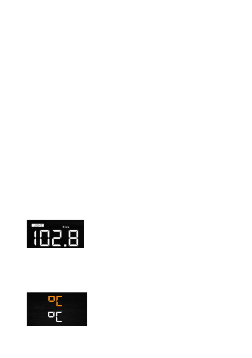
6.4.8 Temperature
t in/outdoor temperature unit ( C or
4) Relative Pre
Thu
altitude of 1000 feet (305 m), but the relative pre
(1016 mb).
T
average sea-level pressure around the world. Relative pressure
measurements greater than 29.92 inHg (1013 mb) are consider
pressure an
c
T
reporting station near you (the internet is the best source
bar
and set your weather station to match the
6.4.7 Light
- Press the SET key 15th to selec
20
Table of contents
Other Foshk Weather Station manuals


Popular Weather Station manuals by other brands

Ambient Weather
Ambient Weather WS-1950 manual

Hama
Hama EWS-800 operating instructions

Bresser
Bresser ClimateTemp NBF instruction manual

Auriol
Auriol IAN 94604 Operation and safety notes

La Crosse Technology
La Crosse Technology WS-9032U instruction manual

Oregon Scientific
Oregon Scientific LW301 user manual


WeatherBug
WeatherBug Weather Station Installation, operation and maintenance manual

NATURE & DECOUVERTES
NATURE & DECOUVERTES 53156650 manual

Celestron
Celestron 47001 Using instructions

LFF
LFF LWS163 user manual

La Crosse Technology
La Crosse Technology 308-1451 instruction manual

Hama
Hama EWS-2050 operating instructions