Fostex PM841 User manual

professional studio monitor
- Reference Manual -
Warnings and Precautions
Important Safety Instructions
FCC (U.S.A.) & ICES-003 (Canada) Information
Introduction & Unpacking
Setup Instructions
Setup Instructions - continued
Back Panel Overview
Product Specifications
Cable and Wiring Information
Product Cleaning Instructions
Declaration of EC Directive
p-2
p-2
p-3
p-4
p-5
p-6
p-6
p-7
p-7
p-7
p-8
CAUTION: TO PREVENT ELECTRIC SHOCK, MATCH
WIDEBLADEOFPLUGTOWIDESLOT,FULLYINSERT.
ATTENTION: POUR PREVENIR LES CHOCS ELECTRIQUES,
APARDELAFENTELARGE,FOND.
WARNING:Toreducetheriskoffireorelectricshock,do
notexposethisapparatustorainormoisture.
AVIS: Pour réduire le risque dʼincendie ou de choc électrique,
ne pas exposer cet appareil sous la pluie et lʼhumidité.
CAUTION: Use of any controls or adjustments or perfor-
manceofproceduresotherthanthosehereinspecifiedmay
resultinhazardousradiationexposure.
ATTENTION: L'utilisation de tout contrôle ou de réglages ou
de procédures autres que celles indiquées ci-après peut
entraîner une exposition à des radiations dangereuses.
WARNING: Changes or modifications to this unit not
expresslyapprovedbythepartyresponsibleforcompliance
couldvoidtheuser’sauthoritytooperatetheequipment.
AVIS: Les changements ou modifications à cette unité
n'étant pas expressément approuvé par la partie respon-
sable de la conformité pourrait annuler l'autorité de
l'utilisateur de faire fonctionner l'équipement.
WARNING:Donotplacetheunitontopofanysoft,porous,
orsensitivesurfacestoavoiddamagingthesurface. Usea
protectivebarrierbetweentheunitandsurfacetoprotectthe
surface.
AVIS: Ne placez pas l'appareil au-dessus de toutes les
surfaces souples, poreux, ou sensibles pour éviter
d'endommager la surface. Utilisez une barrière de protection
entre l'unité et la surface à protéger la surface.
WARNING: Use of this unit near fluorescent lighting may
causeinterferenceregardinguseoftheremote.Iftheunitis
displayingerraticbehaviormoveawayfromanyfluorescent
lighting,asitmaybethecause.
AVIS: L'utilisation de cet appareil à proximité d'éclairage
fluorescent peut provoquer des interférences sur l'utilisation
de la télécommande. Si l'appareil affiche un comportement
erratique s'éloigner de tout éclairage fluorescent, telle qu'elle
peut être la cause.
CAUTION: Danger of explosion if battery is incorrectly
replaced.Replaceonlywiththesameorequivalenttype.
ATTENTION: Danger dʼexplosion si les piles sont rempla-
cées de façon incorrect. Remplacer les piles seulement par le
même type de pile ou lʼéquivalent.
WARNING: Do not install this equipment in a confined
spacesuchasabookcaseorsimilarunit.
AVIS: Ne pas installer cet équipement dans un espace
confiné comme une bibliothèque ou une unité similaire.
WARNING:Mainsplugisusedasdisconnectdeviceandit
shouldremainreadilyoperableduringintendeduse.Inorder
todisconnecttheapparatusfromthemainscompletely,the
mains plug should be disconnected from the mains socket
outletcompletely.
AVIS: La prise du secteur est utilisé pour déconnecter le
système. La prise du secteur ne doit pas être obstruée ou doit
être facilement accessible pendant son utilisation. Pour être
complètement déconnecté de lʼalimentation dʼentrée, la prise
doit être débranchée du secteur.
WARNING: TO REDUCE THE RISK OF ELECTRIC
SHOCK,DONOTREMOVECOVER(ORBACK).
AVERTISSEMENT:POURRÉDUIRELERISQUEDECHOCÉLEC-
TRIQUE,NEPASENLEVERLECOUVERCLE(NILEDOS).
NO USERSERVICEABLE PARTS INSIDE. REFER
SERVICINGTOQUALIFIEDSERVICEPERSONNEL.
AUCUNEPIÈCEÀL'INTÉRIEUR.ENTRETIEN DEPERSONNEL-
QUALIFIE.
Thelightningflashwitharrowheadsymbol,within
anequilateraltriangle,isintendedtoalerttheuser
to the presence of uninsulated “dangerous
voltage” within the product’s enclosure that may
be of sufficient magnitude to constitute a risk of
electricshocktopersons.
Le symbole de lʼéclair fléché dans un triangle
équilatéral, est destiné à alerter lʼutilisateur de la
présence dʼune “tension dangereuse” dans le
boîtier du produit qui peuvent être des ampleur
suffisante pour constituer un risque
dʼélectrocution aux personnes.
Warnings and Precautions
•
•
•
•
•
•
•
•
•
Important Safety Instructions
Read these Instructions.
Lisez ces instructions.
Keep these Instructions.
Conservez ces instructions.
Heed all Warnings.
Respectez tous les avertissements.
1.
2.
3.
Follow all instructions.
Suivez toutes les instructions.
Do not use this apparatus near water.
Ne pas utiliser cet appareil près de l'eau.
Clean only with a dry cloth.
Nettoyer uniquement avec un chiffon sec.
4.
5.
6.
The exclamation point within an equilateral
triangle is intended to alert the user to the
presence of important operating and mainte-
nance (servicing) instructions in the literature
accompanyingtheappliance.
Le point d'exclamation à l'intérieur d'un triangle
équilatéral est destiné à attirer l'attention de
l'utilisateur sur la présence d'instructions impor-
tantes sur l'emploi ou de la maintenance
(réparation) de l'appareil dans la documentation
fournie.
CAUTION
RISKOFELECTRICSHOCK
DONOTOPEN
ATTENTION
NESPASOUVRIR
RISQUE Dʼ ÉLECTROCUTION

Do not block any ventilation openings. Install in accor-
dance with the manufacturer’s instructions.
Ne pas bloquer les ouvertures de ventilation. Installer
conformémentauxinstructionsdufabricant.
Do not install near any heat sources such as radiators,
heat registers, stoves, or other apparatus (including ampli-
fiers) that produce heat.
Nepasinstallerprèsdesourcesdechaleurtellesqueradia-
teurs,registres dechaleur,poêles ou autresappareils(y
comprislesamplificateurs)produisantdelachaleur.
Do not defeat the safety purpose of the polarized or
grounding - type plug. A polarized plug has two blades with
one wider than the other. A grounding type plug has two
blades and a third grounding prong. The wide blade or the
third prong are provided for your safety. When the provided
plug does not fit into your outlet, consult an electrician for
replacement of the obsolete outlet.
Nedétruisezpaslasécuritédelaterreoupolarisées-fiche.
Unefichepolariséepossèdedeuxlamesdontuneestplus
largequel'autre.Uneprisedeterrepossèdedeuxlameset
unebrochedeterre.Lalamelargeoulatroisièmebroche
sont prévues pour votre sécurité. Si la fiche fournie ne
rentrepasdansvotreprise,consultezunélectricienpour
remplacerlapriseobsolète.
Protect the power cord from being walked on or pinched
particularly at plugs, convenience receptacles, and the
point where they exit from the apparatus.
Protégezlecordond'alimentationd'êtrepiétinéoupincé,
particulièrement au niveau des fiches, des prises, et le
pointoùilssortentdel'appareil.
Only use attachments/accessories specified by the manu-
facturer.
N'utilisezquedesaccessoiresspécifiésparlefabricant.
7.
8.
9.
10.
11.
12.
13.
14.
15.
16.
17.
1.IMPORTANTNOTICE
This product, when installed as indicated in the instructions
containedinthismanual,meetsFCCandICES-003requirements.
Changes or modifications not expressly approved by Fostex
Companyforcompliancecouldvoidtheuser’sauthoritytooperate
theequipment.DONOTMODIFYTHISPRODUCT.
2.IMPORTANT
InordertocomplywithFCCandICES-003requirements,usehigh
quality shielded cables for connection to accessories and / or
anotherproducts.Ifanycablesaresuppliedwiththisproduct,they
MUSTbeused.Followallinstallationinstructions.Failuretodoso
couldvoidyourFCC/ICES-003authorizationtousethisproductin
theUSA/Canada.
3.NOTE
Thisequipmenthasbeentestedandfoundtocomplywiththelimits
foraClassBdigitaldevice,pursuanttoPart15oftheFCCRules.
Theselimitsaredesignedtoprovidereasonableprotectionagainst
harmful interference in a residential installation. This equipment
generates,usesandcanradiateradiofrequencyenergyand,ifnot
installed and used in accordance with instructions, may cause
harmfulinterferencetoradiocommunications.However,thereisno
guaranteethatinterferencewillnotoccurinaparticularinstallation.
Ifthisequipmentdoescauseharmfulinterferencetoradioor
televisionreception, which can be determined byturningthe
equipment off and on, the user is encouraged to correct the
interferencebyoneormoreofthefollowingmeasures:
Reorientorrelocatethereceivingantenna.
Increase the separation between the equipment and
receiver.
Connect the equipment into an outlet on a circuit different
fromthattowhichthereceiverisconnected.
Consultthedealeroranexperiencedradio/TVtechnicianfor
help.
4.CompliancewithPart15ofFCCRulesandCanadian
ICES-003.
ThisdevicecomplieswithPart15oftheFCCRules.Operation
issubjecttothefollowingtwoconditions:(1)Thisdevicemay
notcauseharmfulinterference,and(2)thisdevicemustaccept
any interference received, including interference that many
causeundesiredoperation.
ThisClassBdigitalapparatuscomplieswithCanadianICES-
003.
CetappareilnumériquedelaclasseBestconformeàlanorme
NMB-003duCanada.
•
•
•
•
Use only with the cart, stand, tripod,
bracket, or table specified by the manu-
facturer,orsoldwiththeapparatus.When
acartisused, use cautionwhenmoving
the cart/apparatus combination to avoid
injuryfromtip-over.
Utilisez seulement avec la charrette, position, trépied,
supportoutablespécifiéeparlefabricant,ouavenduavec
lʼappareil. Lorsquʼune charrette est utilisée, utilise la
prudence quand déplacer la combinaison de charrette /
appareilpouréviterlablessuredepointe-sur.
Unplug this apparatus during lightning storms or when
unused for long periods of time.
Débranchez cet appareil pendant les orages ou lorsqu'il
n'estpasutilisépendantdelonguespériodesdetemps.
Refer all servicing to qualified service personnel. Servicing
is required when the apparatus has been damaged in any
way, such as power-supply cord or plug is damaged, liquid
has been spilled or objects have fallen into the apparatus,
the apparatus has been exposed to rain or moisture, does
not operate normally, or has been dropped.
Confiez toute réparation à un personnel qualifié. Une
réparationestnécessairelorsquel'appareilaétéendom-
magédequelquefaçonquececordond'alimentationoula
ficheestendommagé,liquideaétérenverséoudesobjets
sonttombés dans l'appareil,l'appareil a étéexposéàla
pluieouàl'humidité,nefonctionnepasnormalement,ou
s'ilesttombé.
The apparatus shall be used in an open area.
Cetappareildoitêtreutilisédansunendroitaaireouverte.
Apparatus shall not be exposed to dripping or splashing
and that no objects filled with liquids, such as vases, shall
be placed on apparatus.
L'appareilnedoitpasêclaboussuresetaucunobjetneconten-
antdeliquide,telqu'unvase,nedoitêtreplacésurobjet.
Mains plug is used as disconnect device. It shall remain
readily operable and should not be obstructed during
intended use. To completely disconnect the apparatus
from supply mains, the main plug of the apparatus shall be
disconnected from the mains socket outlet completely.
Laprisedusecteuretutilisépoudéconnecterlesystème.
Laprisedusecteurnedoitpasêtreobstruéeoudoitêtre
facilement accessible pendant son utilisation. Pour être
complètement déconnecté de l'alimentation d'entrée, la
prisedoitêtredébranchéedusecteur.
FCC (U.S.A.) & ICES-003 (Canada) Information

p-4
Unpacking
Introduction
Thank you for purchasing the Fostex PM841
/ PM641 Professional Studio Monitor. As with
all Fostex products, the PM841 / PM641 has
been designed to provide superlative perfor-
mance, unquestioned reliability and excep-
tionally high value.
Dedicated 60W (50W: PM641) power
amplifier for 8” (6 1/2”: PM641) woofer,
18W for 4” midrange and 18W for 3/4”
tweeter are individually built-in for high
efficiency and low distortion playback.
The built-in channel divider provides ideally
overlapped frequency crossovers for
smooth connections between the drivers.
Prior to unpacking your Fostex PM841 / PM641 Studio Monitor, carefully inspect the packing mate-
rial for excessive damage. Once it has been determined that the packing material has not been com-
promised, carefully unpack the PM841 / PM641 Studio Monitor and inspect it carefully for obvious
damage. Fostex takes great care in designing packing materials that will survive most expected
impacts during shipping. If any damage is discovered during the inspection process, contact your
Fostex dealer so that this issue can immediately be addressed.
The midrange and tweeter drivers are positioned symmetrically on the Left and Right to minimize
the physical height of the enclosure boxes as well as to minimize the affect of diffraction.
The woofer and the midrange drivers are housed in an individual chamber respectively. The
woofer driver delivers rich and speedy lows in the two-ported bass-reflex chamber. The midrange
driver delivers quality middles in the closed chamber. As the tweeter driver is also sealed struc-
ture itself, there is little interference among the drivers for ideal driving environment.
3-step level adjustments are provided for HIGH FREQ at +1/0/-1 dB and LOW FREQ at +3/0/-3
dB.
The diaphragm for the woofer and midrange is highly rigid with moderate internal loss being made
of highly elastic Kevlar papered by Fostex’s original engineering to perfectly reproduce pulsing
music to sensitive one.
The tweeter diaphragm is UFLC (Urethane Film Laminated Cloth) soft dome type to reproduce
various types of highs keeping its own transparency.
The PM841 / PM641 conforms to ErP directive and pursues energy efficiency. Thus, when
no-signal condition continues for about 25 minutes, it will automatically go into the stand-by mode
and its power withdrawal will become less than 0.5W. During this mode, the power LED color will
change from Blue to Red.
Please take the time to thoroughly read this manual so that you may take full advantage
of all the
benefits of the Fostex PM841 / PM641
Professional Studio Monitor.
•
•
•
•
•
•
•
PM 841 LEFT CABINET PM 841 RIGHT CABINET
•
p-5
Setup Instructions
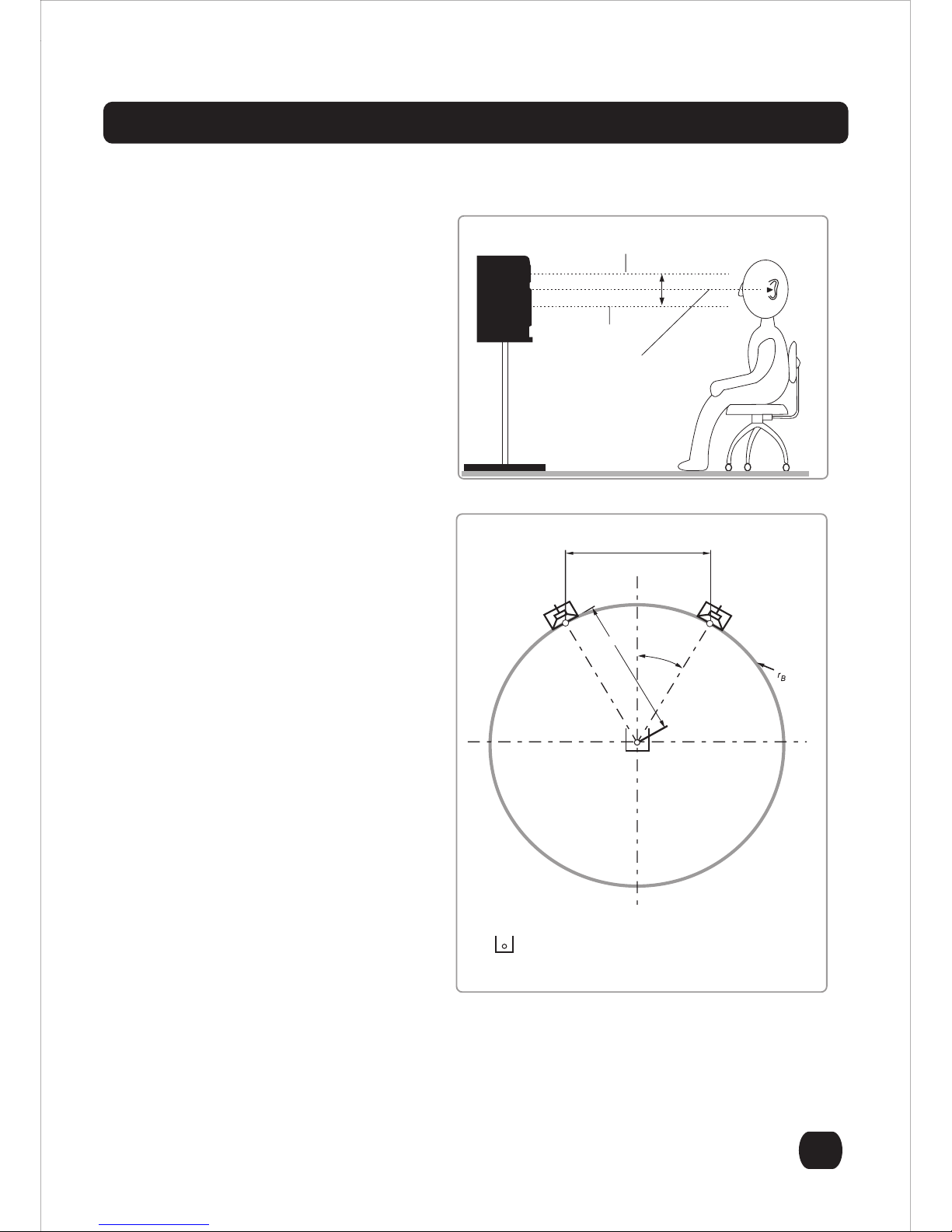
Monitoring Distance = 1 to 2 meters
After carefully unpacking the PM841 /
PM641 Professional Studio Monitor, it is
now time to set up the monitors for the best
acoustic performance in your studio.
The PM841 / PM641 was designed to be
used at a monitoring distance of 1 to 2
meters, typically referred to as the near-
field.
Monitoring Height = the acoustic center
aimed at seated ear height
It is recommended that the PM841 / PM641
be located in such a way that the acoustic
center is located at, or about, seated ear
height (see Figure 1). If this is not possible,
it may be necessary to tilt/aim the monitor
at the listeners ears.
Monitoring Angle = 60 Degrees
The monitoring angle between the left and
right monitors and the listening position
should equal 60 degrees. The easiest way
to determine this is to place the speakers in
such a way that the distance between the
left and right monitor is equal to the moni-
toring distance / listening position (see
Figure 2). It is also recommended that both
speakers be "toed-in" towards the listening
position.
Additional Information
The PM841 / PM641 was designed to be
mounted vertically. This provides for the
most accurate frequency response,
reduces acoustic boundary interference
and provides optimum cooling performance
for the heat sink that is located on the back
of the studio monitor.
Figure 1
Figure 2
Center of the tweeter/mid range
Center of the woofer
Mid-point of the woofer and tweeter/mid range
Reference listening position B:loudspeakerbasewidth
D:monitoringdistance
Left Right
B
30˚
D = B
=B
Unpacking
Introduction
Thank you for purchasing the Fostex PM841
/ PM641 Professional Studio Monitor. As with
all Fostex products, the PM841 / PM641 has
been designed to provide superlative perfor-
mance, unquestioned reliability and excep-
tionally high value.
Dedicated 60W (50W: PM641) power
amplifier for 8” (6 1/2”: PM641) woofer,
18W for 4” midrange and 18W for 3/4”
tweeter are individually built-in for high
efficiency and low distortion playback.
The built-in channel divider provides ideally
overlapped frequency crossovers for
smooth connections between the drivers.
Prior to unpacking your Fostex PM841 / PM641 Studio Monitor, carefully inspect the packing mate-
rial for excessive damage. Once it has been determined that the packing material has not been com-
promised, carefully unpack the PM841 / PM641 Studio Monitor and inspect it carefully for obvious
damage. Fostex takes great care in designing packing materials that will survive most expected
impacts during shipping. If any damage is discovered during the inspection process, contact your
Fostex dealer so that this issue can immediately be addressed.
The midrange and tweeter drivers are positioned symmetrically on the Left and Right to minimize
the physical height of the enclosure boxes as well as to minimize the affect of diffraction.
The woofer and the midrange drivers are housed in an individual chamber respectively. The
woofer driver delivers rich and speedy lows in the two-ported bass-reflex chamber. The midrange
driver delivers quality middles in the closed chamber. As the tweeter driver is also sealed struc-
ture itself, there is little interference among the drivers for ideal driving environment.
3-step level adjustments are provided for HIGH FREQ at +1/0/-1 dB and LOW FREQ at +3/0/-3
dB.
The diaphragm for the woofer and midrange is highly rigid with moderate internal loss being made
of highly elastic Kevlar papered by Fostex’s original engineering to perfectly reproduce pulsing
music to sensitive one.
The tweeter diaphragm is UFLC (Urethane Film Laminated Cloth) soft dome type to reproduce
various types of highs keeping its own transparency.
The PM841 / PM641 conforms to ErP directive and pursues energy efficiency. Thus, when
no-signal condition continues for about 25 minutes, it will automatically go into the stand-by mode
and its power withdrawal will become less than 0.5W. During this mode, the power LED color will
change from Blue to Red.
Please take the time to thoroughly read this manual so that you may take full advantage
of all the
benefits of the Fostex PM841 / PM641
Professional Studio Monitor.
•
•
•
•
•
•
•
PM 841 LEFT CABINET PM 841 RIGHT CABINET
•

p-6
Setup Instructions continued
Back Panel Overview
Once the studio monitors have been placed in their final location, it is time to proceed to connecting
your PM841 / PM641 studio monitors to the mixing console or digital workstation. Connection to the
PM841 can be made using XLR or TRS connectors. The gain control on the back of the monitor
allows continuously variable adjustments to match most input types from -10dBV to +4dBu. The
input is electronically balanced and is compatible with unbalanced sources, although this may
require an adapter. The connection of the PM841 / PM641 to the console/digital workstation should
be done in the following order.
Step 1: Make sure that all equipment has been powered down.
Step 2: Confirm that all gain controls on the monitor and the source are set to the minimum.
Step 3: Connect the source to the PM841 / PM641 monitor.
Step 4: Power up all the source equipment and then turn on the PM841 / PM641 last.
Step 5: Set the gain of both monitors at medium setting and slowly bring up the gain of the console.
Step 6: Adjust the gain of both monitors for balance and for best signal to noise ratio.
Once the above steps have been completed, you are ready to use your PM841 / PM641 monitors.
It is recommended that you now play some familiar audio material and make any final adjustments,
as far as placement or level, to get the optimum performance in your monitoring environment.
1. Continuously variable gain control
This control adjusts the input level to the internal
amplifiers.
2. High Frequency Adjustment
Adjusts the high frequency characteristics around
10kHz within a ± 1dB range.
3. Low Frequency Adjustment
Adjusts the low frequency characteristics around
60Hz within a ± 3dB range.
4. TRS Balanced Input
5. XLR Balanced Input
These are an electronically balanced inputs and are
compatible with both -10dBV and +4dBu signals.
<CAUTION>: These inputs cannot be used simulta-
neously. The TRS input takes the priority and the
XLR input is disabled.
6. Heatsink
The heatsink dissipates heat from the amplifier. It is
important the heatsink receives proper ventilation
and is not placed near any sources of heat.
7. Power Switch
Turns power to the amplifier section on or off. On - position is the spot side.
8. Standard IEC Power Input
This power terminal should be used with a properly grounded three pin power cable, such as the one
provide with the product.
7
8
5
4
3
2
1
6
PM841 Rear Panel View
Product Specifications
Cable and Wiring Information
Product Cleaning Instructions
HOT (+)
XLR
PIN 2
PIN 3
PIN 1
TIP
RINGCOLD (-)
SHIELD (GROUND)
TRS
SHIELD
Prior to cleaning the PM841 / PM641 monitor, the power must be disconnected from the PM841 /
PM641 monitor. Once the power has been terminated, cleaning can be accomplished using a damp
(not wet) cleaning rag. A light common household cleaner can also be used, but care must be taken
not to use harsh cleaning fluids. Regular dusting or cleaning with a damp rag will keep your product
looking new for years.
Use high-quality, shielded cables to connect your mixing
console, workstation or other source to your monitors. Foil-
shielded cables should do quite well. Other high quality cables
that incorporate better shielding will yield an overall higher noise
rejection, lowering your systems susceptibility to external inter-
ference. Another important tip to keep in mind when wiring your
Product improvement may warrant a change of specifications, newer materials or cosmetics, Changes in specifications and features may
be made without notice or obligations.
<SPEAKER SECTION>
Enclosure System 3-way system
Drivers
Woofer
PM841 200 mm / 8”
PM641 165 mm / 6 1/2”
Mid range 100 mm / 4”
Tweeter 19 mm / 0.75” soft dome
Impedance
Woofer 8 Ω
Mid range 4 Ω
Tweeter 4 Ω
<AMPLIFIER SECTION>
Rated Output
Woofer
PM841 60 W
PM641 50 W
Mid range 18 W
Tweeter 18 W
Inputs
Connector ø6 mm TRS phone
(balanced)
XLR-3-31 (balanced)
Input level -10 dBV (TRS phone)
+4 dBu (XLR)
Impedance 20 kΩ or more
High & Low Adjustments
Low ±3 dB at around 60 Hz
High ±1 dB at around 10 kHz
Power Consumption
Normalmode 60 W
Stand-by mode 0.5W
Power Requirements
US/CND 120 VAC, 60 Hz
EUR/UK/AUS 230 VAC, 50/60 Hz
CHN 220 VAC, 50 Hz
Frequency Response
PM841 50 Hz ~ 25 kHz
PM641 55 Hz ~ 25 kHz
<GENERAL>
Cabinet Dimensions
PM841
270.0 (W) x 423.0 (H) x 290.1 (D) mm incl. heatsink
253.5 mm (D) cabinet only
10.63” (W) x 16.65" (H) x 11.42" (D) incl. heatsink
9.98" (D) cabinet only
PM641
248.6 (W) x 375.6 (H) x 290.1 (D) mm incl. heatsink
253.5 mm (D) cabinet only
9.79” (W) x 14.79" (H) x 11.42" (D) incl. heatsink
9.98" (D) cabinet only
Net Weight
PM841 13.36 kg, 29.45 lbs.
PM641 11.10 kg, 24.47 lbs.
100 1k 10k
20 (Hz) 50 200 500 2k 5k 20k 50k
PM841 PM641
system is to route all line level cables away from the AC and other power sources, this will reduce the
probability of having AC hum emanating from your studio monitors.

p-7
Setup Instructions continued
Back Panel Overview
Once the studio monitors have been placed in their final location, it is time to proceed to connecting
your PM841 / PM641 studio monitors to the mixing console or digital workstation. Connection to the
PM841 can be made using XLR or TRS connectors. The gain control on the back of the monitor
allows continuously variable adjustments to match most input types from -10dBV to +4dBu. The
input is electronically balanced and is compatible with unbalanced sources, although this may
require an adapter. The connection of the PM841 / PM641 to the console/digital workstation should
be done in the following order.
Step 1: Make sure that all equipment has been powered down.
Step 2: Confirm that all gain controls on the monitor and the source are set to the minimum.
Step 3: Connect the source to the PM841 / PM641 monitor.
Step 4: Power up all the source equipment and then turn on the PM841 / PM641 last.
Step 5: Set the gain of both monitors at medium setting and slowly bring up the gain of the console.
Step 6: Adjust the gain of both monitors for balance and for best signal to noise ratio.
Once the above steps have been completed, you are ready to use your PM841 / PM641 monitors.
It is recommended that you now play some familiar audio material and make any final adjustments,
as far as placement or level, to get the optimum performance in your monitoring environment.
1. Continuously variable gain control
This control adjusts the input level to the internal
amplifiers.
2. High Frequency Adjustment
Adjusts the high frequency characteristics around
10kHz within a ± 1dB range.
3. Low Frequency Adjustment
Adjusts the low frequency characteristics around
60Hz within a ± 3dB range.
4. TRS Balanced Input
5. XLR Balanced Input
These are an electronically balanced inputs and are
compatible with both -10dBV and +4dBu signals.
<CAUTION>: These inputs cannot be used simulta-
neously. The TRS input takes the priority and the
XLR input is disabled.
6. Heatsink
The heatsink dissipates heat from the amplifier. It is
important the heatsink receives proper ventilation
and is not placed near any sources of heat.
7. Power Switch
Turns power to the amplifier section on or off. On - position is the spot side.
8. Standard IEC Power Input
This power terminal should be used with a properly grounded three pin power cable, such as the one
provide with the product.
7
8
5
4
3
2
1
6
PM841 Rear Panel View
Product Specifications
Cable and Wiring Information
Product Cleaning Instructions
HOT (+)
XLR
PIN 2
PIN 3
PIN 1
TIP
RINGCOLD (-)
SHIELD (GROUND)
TRS
SHIELD
Prior to cleaning the PM841 / PM641 monitor, the power must be disconnected from the PM841 /
PM641 monitor. Once the power has been terminated, cleaning can be accomplished using a damp
(not wet) cleaning rag. A light common household cleaner can also be used, but care must be taken
not to use harsh cleaning fluids. Regular dusting or cleaning with a damp rag will keep your product
looking new for years.
Use high-quality, shielded cables to connect your mixing
console, workstation or other source to your monitors. Foil-
shielded cables should do quite well. Other high quality cables
that incorporate better shielding will yield an overall higher noise
rejection, lowering your systems susceptibility to external inter-
ference. Another important tip to keep in mind when wiring your
Product improvement may warrant a change of specifications, newer materials or cosmetics, Changes in specifications and features may
be made without notice or obligations.
<SPEAKER SECTION>
Enclosure System 3-way system
Drivers
Woofer
PM841 200 mm / 8”
PM641 165 mm / 6 1/2”
Mid range 100 mm / 4”
Tweeter 19 mm / 0.75” soft dome
Impedance
Woofer 8 Ω
Mid range 4 Ω
Tweeter 4 Ω
<AMPLIFIER SECTION>
Rated Output
Woofer
PM841 60 W
PM641 50 W
Mid range 18 W
Tweeter 18 W
Inputs
Connector ø6 mm TRS phone
(balanced)
XLR-3-31 (balanced)
Input level -10 dBV (TRS phone)
+4 dBu (XLR)
Impedance 20 kΩ or more
High & Low Adjustments
Low ±3 dB at around 60 Hz
High ±1 dB at around 10 kHz
Power Consumption
Normalmode 60 W
Stand-by mode 0.5W
Power Requirements
US/CND 120 VAC, 60 Hz
EUR/UK/AUS 230 VAC, 50/60 Hz
CHN 220 VAC, 50 Hz
Frequency Response
PM841 50 Hz ~ 25 kHz
PM641 55 Hz ~ 25 kHz
<GENERAL>
Cabinet Dimensions
PM841
270.0 (W) x 423.0 (H) x 290.1 (D) mm incl. heatsink
253.5 mm (D) cabinet only
10.63” (W) x 16.65" (H) x 11.42" (D) incl. heatsink
9.98" (D) cabinet only
PM641
248.6 (W) x 375.6 (H) x 290.1 (D) mm incl. heatsink
253.5 mm (D) cabinet only
9.79” (W) x 14.79" (H) x 11.42" (D) incl. heatsink
9.98" (D) cabinet only
Net Weight
PM841 13.36 kg, 29.45 lbs.
PM641 11.10 kg, 24.47 lbs.
100 1k 10k
20 (Hz) 50 200 500 2k 5k 20k 50k
PM841 PM641
system is to route all line level cables away from the AC and other power sources, this will reduce the
probability of having AC hum emanating from your studio monitors.

© PRINTED IN CHINA JAN. 2013 565364
FOSTEX CO.
1-1-109 Tsutsujigaoka, Akishima City, Tokyo, 196-8550, Japan
Declaration of EC Directive
This equipment is compatible with the EMC Directive (2004/108/EC) - Directive on approximation of member nation's ordinance concerning
the electromagnetic compatibility and with the Low Voltage Directive (73/23/EEC) - Directive on approximation of member nation's
ordinance concerning electric equipment designed to be used within the specified voltage range.
The Affect of Immunity on This Equipment
The affect of the European Specification EN61000-6-1 (coexistence of electromagnetic waves - common immunity specification) on this
equipment are as shown below.
In the electrical fast transient/burst requirements, surge, conducted disturbances by radio-frequency fields, power frequency magnetic
field, radiate electromagnetic field requirements and static electricity discharging environment, this could be affected by generation of
noise in some cases.
FOSTEX DISTRIBUTORS LIST IN EUROPE
* Including non-EU countries (as of January 2012)
<AUSTRIA>
NAME: Mega Audio GmbH
ADD: Stromberger Str. 32, D-55411 Bingen, Germany
TEL: (+49) 6721-94330, FAX: (+49) 6721-32046
<BULGARIA>
NAME: Shark Art
ADD: 15 Hristo Popovich Str., Varna 9000, Bulgaria
TEL: (+359) 52-600172, FAX: (+359) 52-250578
<CZECH REPUBLIC>
NAME: Praha Music Center spol s.r.o.
ADD: Ocelarska 937/39, Praha 9, 190 00, Czecho
TEL: (+420) 226-011-111, FAX: (+420) 226-011-112
<DENMARK>
NAME: Benum Nordic A/S
ADD: Meterbuen 18, Skovlunde, 2740 Denmark
TEL: (+45) 4451-8900, FAX: (+45) 4451-8911
<FINLAND>
NAME: Noretron Oy Audio
ADD: P. O. Box 22, FIN-02631 Espoo, Finland
TEL: (+358) 9-5259330, FAX: (+358) 9-52593352
<FRANCE>
NAME: Sennheiser France
ADD: 128 bis, avenue Jean-Jaures, 94851 Ivry-sur-Seine Cedex,
France
TEL: (+33) 1 4987 0300, FAX: (+33) 1 4987 0324
<GERMANY>
NAME: Mega Audio GmbH
ADD: Stromberger Str. 32, D-55411 Bingen, Germany
TEL: (+49) 6721-94330, FAX: (+49) 6721-32046
<GREECE>
NAME: Bon Studio S. A.
ADD: 6 Zaimi Street, Exarchia, 106.83 Athens, Greece
TEL: (+30) 210-3809-605, 606, 607, 608
FAX: (+30) 210-3845-755, 210-3827-868
<HUNGARY>
NAME: ATEC Hungary Kft
ADD: H-110/ Budapest, Fogado u. 3, Hungary
TEL: (+36) 1-4319005, FAX: (+36) 1-4319006
<ITALY>
NAME: Proel S. p. A.
ADD: Zona Via Alla Ruenia, 37/43 64027 - Sant’Omero (Teramo),
Italy
TEL: (+39) 0861-81241, FAX: (+39) 0861-887862
<THE NETHERLANDS>
NAME: IEMKE ROOS AUDIO B. V.
ADD: Kuiperbergweg 20, 1101 AG Amsterdam, The Netherlands
TEL: (+31) 20-697-2121, FAX: (+31) 20-697-4201
<NORWAY>
NAME: Siv. Ing. Benum AS
ADD: P. O. Box 145, Vinderen, 0319 Oslo, Norway
TEL: (+47) 2213 9900, FAX: (+47) 2214 8259
<POLAND>
NAME: Mega Music Spolka z o.o
ADD: Ul. Lesna 15, 81-876 Sopot, Poland
TEL: (+48) 58-551-18-82, FAX: (+48) 58-551-18-72
<SPAIN>
NAME: Letusa S. A.
ADD: C/Laguna 10, 28923 Alcorcon, Madrid, Spain
TEL: (+34) 91-4862800, 91-4470898, FAX: (+34) 91-6414597
<SWEDEN>
NAME: Benum Nordic A/S
ADD: Aldermansvagen 17, 171 48 Solna, Sweden
TEL: (+46) 8 207710
<SWITZERLAND>
NAME: Audio Bauer Pro AG
ADD: Bernerstrasse-Nord 182, CH-8064 Zurich, Switzerland
TEL: (+41) 1-4323230, FAX: (+41) 1-4326558
<UK>
NAME: SCV London
ADD: 40 Chigwell Lane, Oakwood Hill Industrial Estate, Loughton,
Essex IG10 3NY U. K.
TEL: (+44) 20-8418-0778, FAX: (+44) 20-8418-0624
This manual suits for next models
1
Table of contents
Other Fostex Speakers manuals

Fostex
Fostex PX-5HS User manual

Fostex
Fostex FW137 User manual

Fostex
Fostex FE166e User manual

Fostex
Fostex FE83 User manual

Fostex
Fostex FW187 User manual

Fostex
Fostex Studio Monitor PM-1 User manual

Fostex
Fostex PM0.3d User manual

Fostex
Fostex FE83En User manual

Fostex
Fostex P650K User manual

Fostex
Fostex PM0.1 User manual

Fostex
Fostex 6301D User manual

Fostex
Fostex NF-1 User manual

Fostex
Fostex Dome dome tweeter User manual

Fostex
Fostex P800-E User manual

Fostex
Fostex Dome Tweeter FT207D User manual

Fostex
Fostex 6301DT User manual

Fostex
Fostex 6301BEAV User manual

Fostex
Fostex FF85K User manual

Fostex
Fostex FF225K User manual

Fostex
Fostex Speaker User manual


