Foto Walser VE-150 User manual

Gewerbering 26
86666 Burgheim
Tel. +49 84 32 / 9489-0
Fax. +49 84 32 / 9489 - 8333
E-mail: info@foto-walser.de
www.foto-walser.de
Copy of Instruction Manual
Studio Flash
Series VE-150 to VE-400

Content
1. How to understand the instruction manual......................................3
1.1. Symbols on the device ................................................................3
1.2. Symbols in this manual ...............................................................4
2. Important safety notes......................................................................4
3. Unpack and check device ..................................................................8
4. Operation of the device ....................................................................9
4.1 Overview of device elements.......................................................9
4.2Quick-start guide........................................................................10
5. Demount and mount protection cap ..............................................11
6. Mount and dismount reflector........................................................12
7. Screw modeling light in and out......................................................13
8. Connect device to power supply.....................................................14
9. Switch the device on and off...........................................................15
10. Adjusting the device........................................................................16
10.1 Adjust flash output...................................................................16
10.2 Adjust modeling lamp ..............................................................17
10.3 Switch acoustic stand-by indicator on and off.........................17
10.4 Prepare and adjust flash trigger...............................................18
Prepare flash trigger via camera 18
Prepare flash trigger via remote receiver (optional) 18
Switch flash trigger via built-in photo cell on and off 18
11. Mount device on tripod (optional)..................................................19
12. Mount reflecting umbrella (optional) .............................................20
13. Switch modeling light on and off.....................................................20
14. Trigger flash.....................................................................................21
15. Transportation and storage.............................................................23
16. Solve problems................................................................................23
17. Maintenance of the device..............................................................24
17.1 Continuous inspection and maintenance of the device ..........24
17.2 Cleaning of the device..............................................................24
17.3 Replacing the flash tube...........................................................25
17.4 Replacing the micro-fuse .........................................................27
17.5 Charging the flash capacitor ....................................................28
18. Accessories and options..................................................................29
19. Spare parts ......................................................................................29
20. Disposal and environment protection.............................................29
21. Technical specifications...................................................................30
22. Overview of the operating panel ....................................................31
22.1. Overview of the functions of operating controls...................32

We would like to thank you for your confidence and wish you much joy and
success with your studio flash.
The walimex pro Studio Flash series VE was developed specifically for the
ambitious beginner and for the professional user.
The VE series is perfectly suited for studio, portrait, person, nude, and product
photography.
The main features of your device are as follows:
fast recycling time and quick flash sequences
very quiet cooling
user friendly operation panel with foil buttons
variation range from 1/1 to 1/32.
Please read these instructions carefully before using your device for the
first time. It includes everything you need to know to avoid physical
injuries and damages.
Please pay attention to all safety notes in this instruction manual.
Please keep this manual safe. If you are selling or leaving the device to
another person, please ensure to hand this manual over as well.
1. How to understand this instruction manual
1.1. Symbols on the device
This symbol means that your device meets the safety
requirements of all relevant European Directives.
This symbol means that your device must be disposed of at local
disposal areas.
1.2. Symbols in this manual
Symbol
Meaning
Indicates the handling and consequences of safety
notes.
WARNING
Indicates a hazardous situation which, if not avoided,
may result in a serious injury or death.
CAUTION
Indicates a hazardous situation which, if not avoided,
may result in minor or moderate injury.
NOTE:
Indicates potential material damage and other
important information regarding your device.
2. Important Safety Notes
WARNING
Risk of retina damage
The flash light could damage the retina leading to the loss of vision, if the
flash is trigged in close distance to persons or animals.
Please do not trigger a flash in close distance to the eyes of persons or
animals.
Please ensure, that the distance between persons and animals is at least
2m. Please avoid looking into the flash directly.
4

WARNING
Danger of crashing, crushing, burning, and fire due to device toppling over
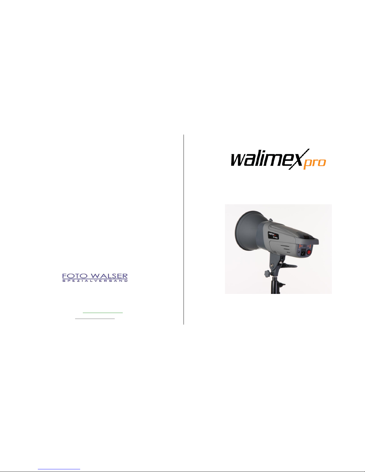
The weight of the device is, depending on the model (VE-150 to VE-400), up
to 2.5kg. The modeling lamp, flash tube and reflector can heat up to 240°C.
Ensure that the device is always kept in a tilt- and skid-resistant position
and stored securely.
Keep out of reach of children and animals. They could knock over the
device.
Avoid placing cables where they could be tripped over. The device could
be knocked over.
WARNING
Danger of electric shock, burn hazard
Please note that the device is still connected to the supply voltage when it is
switched off. Only when you disconnect the device from the supply voltage
by unplugging the power cord, it is really de-energized.
Switch off the device when it is not in use.
Switch off the device before assembly and maintenance and disconnect
from power supply by unplugging the power cord.
Discharge the device before maintenance measures.
Protect your device against accidental power-on.
Cut off voltage supply when not in use for a longer period of time by
unplugging the power cord.
WARNING
Danger of electric shock, fire through short-circuit
A short circuit could be caused by defective cables and due to moisture or
wetness. A short circuit can heat up the conductors resulting in the melting of
their insulation or the conductors themselves. This could lead to fire.
Please use exclusively the original cables, which are provided with the
device. They are tuned for your device and guarantee the necessary safety
for you and your device.
Do not operate the device with wet hands or feet.
Only use the device in dry rooms.
Do not use the device outdoors.
Clean the device exclusively as described in this instruction manual.
Ensure that cables and conductors are not damaged. Damage could be
caused due to heat impact, chemical influence or due to mechanical
impacts such as rubbing, bending, tearing, rolling over, or nibbling
animals.
Prevent your device from falling.
In the case of falling, please have an electrician check the device before
switching it on again.
If your device is damaged or if you notice a burning smell:
Disconnect the power supply immediately by unplugging the power cord
and setting the on/off switch to 0 (OFF). Never operate your device with a
damaged casing, defective lamps or a damaged power cord. Do not open
the device. Never repair the device on your own. Have the device repaired
exclusively by an electrician.
Please follow this instruction manual for maintaining your device.
Please only use spare parts which are conform to the required
specifications. See Technical specifications.
6
5

WARNING
Danger of fire by overheating
The device can overheat if you operate it with mounted protection cap or
with covered ventilation slots. The device itself or easily inflammable
materials in close distance could catch fire.
Do not operate the device with mounted protection cap.
Do not cover the ventilation slots of the device during operation.
Remove easily inflammable materials from the surroundings of the
device.
Please just use spare parts, which are conform to the required
specifications. See Technical Specifications.
WARNING
Danger of fire due to hot device components
The modeling lamp and flash tube could heat up to 240°C, the reflector up to
75°C and the flash housing up to 45°C. Easily inflammable materials could
catch fire, if they get in contact with hot device components.
Do not cover the ventilation slots of the device during operation.
Remove easily inflammable materials from the surroundings of the
device.
WARNING
Danger of burning on hot device components
The modeling lamp and flash tube could heat up up to 240°C, the reflector up
to 75°C and the flash housing up to 45°C.
Do not touch device elements during use and during the cooling down
phase.
Allow for device to cool down completely before beginning assembly or
maintenance measures.
WARNING
Danger of cutting and splitting due to breaking modeling lamp or breaking
or bursting flash tube
Even small residues of skin oil on the flash tubes can lead to the splitting of
the lamp, due to the high heat impact during operation. Broken glass can
hurt eyes and skin.
Treat the modeling lamp and flash tube carefully to avoid them from
breaking.
Do not touch the flash tube with bare hands. Only touch the flash tube at
the plastic socket or with a clean cloth or with clean gloves.
Avoid touching the flash tube accidentally when mounting or changing
accessories.
3. Unpack and check the device
1. Please unpack the device carefully.
NOTE: Keep the styrofoam packaging for later storage and transport of the
device.
2. Please check if the scope of delivery is complete:
1 VE Studio Flash with protection cap
1 Reflector
1 modeling lamp
1 sync cable
1 power cord
1 instruction manual in German and English.
3. Please check if the scope of delivery is undamaged.
NOTE: If the scope of delivery is incomplete or damaged, please contact
32 / 9489 - 0.
NOTE:
We reserve the right to make technical and optical modifications in the course
of product improvement.
Illustrations can deviate from the actual object.
7
8
7

4. Operation of the device
4.1. Overview of device elements
A
Reflector
B
Unlocking lever
C
Photo cell (hidden)
The photo cell is located under the red,
transparent cover on top of the device
D
Handle
E
Ventilation slots
F
Umbrella holder
G
Tripod mounting
4.2. Quick-start guide
NOTE:
The detailed instruction for the following operations can be found in the
respective chapters in this instruction manual.
Maintain the order of the following operating steps when using the device for
the first time to avoid damaging the device.
WARNING
Please pay attention to the safety notes in the respective chapters
throughout operation.
1. Dismount protection cap.
2. Mount reflector.
3. Insert modeling lamp.
4. Mount umbrella (optional).
5. Connect device to power supply.
6. Switch on device.
7. Adjust modeling lamp.
8. Adjust flash output.
9. Adjust acoustic stand-by indicator.
10. Prepare flash trigger.
11. Mount device on tripod (optional).
A
B
C
F
E
D
G
1010
9

5. Demount and mount protection cap
WARNING
Danger of bursting flash tube
Ensure not to accidentally touch the flash tube with bare hands.
A
Openings for reflector or protection cap
1. Demounting of protection cap:
Remove safety cap from unlocking lever.
Push back unlocking lever and keep it pressed.
Turn protection cap counterclockwise as far as it will go and take off from
the device.
Release the unlocking lever.
2. Mounting of protection cap:
Let the device cool down.
WARNING! Danger of fire due to overheating. Danger of burning. Let
the device cool down for approx. 30 minutes.
Push back unlocking lever and keep it pressed.
Plug the protection cap into the three openings on the device, turn it
clockwise and listen for the cap to snap into place.
Release the unlocking lever.
Stick the safety cap onto the unlocking lever.
6. Mount and demount reflector
WARNUNG
Danger of bursting flash tube
Ensure not to accidentally touch the flash tube with bare hands.
A
Openings for reflector or protection cap
1. Mounting the reflector:
Switch off device.
See Switch the device on and off.
Let device cool down.
WARNING! Danger of burning on reflector, modeling lamp and flash
tube. Let the device cool down for approx. 30 minutes.
Demount protection cap.
See Demount and mount protection cap.
Push back unlocking lever and keep pressed.
Plug the reflector into the openings, so that the opening for the umbrella
(optional) faces downward.
Turn reflector clockwise and listen for the reflector to snap into place.
Release the unlocking lever.
Stick the safety cap onto the unlocking lever.
A
A
1111
12

2. Demount reflector:
WARNING! Danger of burning on reflector, modeling lamp and flash
tube. Let the device cool down for approx. 30 minutes.
Remove safety cap from unlocking lever.
Push back unlocking lever and keep pressed.
Turn reflector counterclockwise as far as it will go and take off from the
device.
Mount protection cap.
See Demount and mount protection cap.
7. Screw modeling light in and out
WARNING
Danger of bursting of flash tube due to skin grease
Ensure not to accidentally touch the flash tube with bare hands.
A
Modeling light
B
Socket
1. Switch off device.
See Switch device on and off.
2. Unplug power cord.
3. Let device cool down.
WARNING! Danger of burning on reflector, modeling lamp and flash
tube. Let the device cool down for approx. 30 minutes.
4. Screw in modeling lamp:
If the protection cap is mounted:
Demount protection cap.
See Dismount and mount protection cap.
Carefully screw modeling lamp into the socket.
5. Screw out modeling lamp:
Remove the modeling bulb from the socket.
Demount protection cap.
See Demount and mount protection cap.
8. Connect device to power supply
1. Switch off device.
See Switch device on and off.
2. Compare the local power network with the connected load of the device.
94890.
3. Connect power cord to the socket on the device and to the power
outlet.
B
A
13
14

9. Switch the device on and off
1. If the protection cap is mounted:
Remove protection cap.
See Demount and mount protection cap.
WARNING! Danger of fire due to heat accumulation. Never use the
device with mounted protection cap.
2. Switch on device:
Set main switch to I (ON).
The digital display OUTPUT POWER shows the currently selected flash
output.
The LED stand-by indicator lights up, when the adjusted flash output is
reached.
NOTE: An integrated soft-start prevents the flash tube from damage. It
will take 1-2 seconds until the flash output is reached.
The modeling lamp lights up, if it was switched on, when the device was
switched off.
The LED AUDIO lights up, if the acoustic stand-by indicator was switched
on, when the device was switched off.
LED of SLAVE function light up, if photo cell was switched on.
3. Switch off device:
Set main switch to 0 (OFF).
All displays will go out.
If the modeling light was switched on:
The modeling light goes out.
NOTE: A special discharge function releases the residual voltage in the
device after it has been switched off. You cannot stop this safety function.
Device automatically flashes after adjusting the flash output.
10. Adjusting the device
10.1. Adjust flash output
You can regulate the power of the flashes according to the chart below.
Flash output
Check value
F-stops
6.0
1 (full power)
5.0
1/2
4.0
1/4
3.0
1/8
2.0
1/16
1.0
1/32
1. Switch on device.
See Switch device on and off.
2. Press push button or push buttonuntil the digital display OUTPUT
POWER shows the desired output. LED stand-by indicator lights up.
When the device has reached the adjusted flash output, LED TEST lights up.
3. Trigger test flash:
Press push-button TEST.
The LED TEST goes out and does not light up again until the device has
reached the adjusted flash output.
14
15
16

10.2. Adjust modeling light
You can adjust the modeling light via 7 regulating taps. The modeling light can
only be adjusted independently from the flash output.
1. Switch on device.
See Switch device on and off.
2. Press push button MODEL1x.
The modeling light is switched on.
The LED MODEL lights up.
3. Press push button MODEL, until the modeling light has the desired power.
The digital display OUTPUT POWER shows the respective flash output.
4. Switch off modeling light:
Press push button MODEL until LED MODEL goes out.
The modeling light goes out.
The LED MODEL goes out.
10.3. Switch acoustic stand-by indicator on and off
1. Switch on device. See Switch device on and off.
2. Switch on acoustic stand-by indicator:
Press AUDIO push-button.
The LED AUDIO lights up.
When the device has reached the set power output, a short beep can be
heard.
3. Switch off acoustic stand-by indicator:
Press AUDIO push-button.
The LED AUDIO goes out.
After triggering a flash, the modeling lamp goes out briefly and lights up
again when the device has reached the set flash output.
A short beep can be heard when the device has reached the set flash
output.
10.4. Prepare and adjust flash trigger
Prepare flash trigger via camera
NOTE:
Please pay attention to the user information of the camera manufacturer for
flash synchronization.
1. Connect sync cord (included in delivery) with the connecting socket on the
device.
2. The other end of the sync cord should be connected with the PC jack socket
of the camera.
Prepare flash trigger via remote receiver (optional)
NOTE:
Please pay attention to the user information of the manufacturer of the remote
trigger.
1. Connect the cable of the remote receiver to the socket for the sync cord.
Switch flash trigger via built-in photo cell on and off
The photo cell enables the device to trigger via
another external device
IR remote trigger
On-camera flash devices
On-camera flash devices with integrated pre-flashes.
1. Switch on device.
See Switch the device on and off.
2. Switch on photo cell:
Press push-button SLAVE.
The LED SLAVE lights up.
18
1917

3. Switch off photo cell:
Press push-button SLAVE until LED SLAVE goes out.
11. Mount device on tripod (optional)
NOTE:
Please pay attention to the user information of the tripod manufacturer.
CAUTION
Only mount the device to a tripod that is suitable for the weight and
dimensions of the device. See Technical specifications.
Ensure that the tripod with the mounted device is kept in a tilt- and skid-
resistant position.
A
Locking lever
B
Locking wheel
C
Fixture
1. Open locking lever.
2. Open locking wheel.
3. Mount device on tripod.
4. Tighten locking wheel.
5. Tighten locking lever.
12. Mount reflecting umbrella (optional)
Use exclusively reflecting umbrellas with a rod diameter of 8-10mm.
A
Fixture
B
Locking wheel
1. Let the device cool down.
WARNING! Danger of burning on reflector, modeling lamp and flash
tube. Please cool down approx. 30 minutes.
2. Open locking wheel.
3. Insert the rod of the reflecting umbrella into the opening in the reflector
into the fixture as far as it will go.
4. Tighten locking wheel
NOTE: Do not tighten the locking wheel too much as to avoid damages on
the reflecting umbrella.
13. Switch modeling lamp on and off
1. Switch on device.
See Switch device on and off.
2. Switch on modeling lamp:
Press push-button MODEL 1x.
The modeling lamp lights up.
The LED MODEL lights up.
A
B
C
B
A
20
19
20

3. Switch off modeling lamp:
Press push-button MODEL until LED MODEL goes out.
The modelight lamp goes out.
4. The LED MODEL goes out.
NOTE: If you do not switch off the modeling lamp before switching off the
device, the modeling lamp will light up automatically, when switching the
device on again.
14. Trigger flash
WARNING
Danger of fire due to overheating
Continuously rapid sequences of flashes of more than 8 flashes per minute
with high flash output can overheat and damage the device.
Heat accumulation can be the result when using small, narrow reflectors (e.g.
snoots) or grid reflectors at high power with the device pointing downward.
Continuous increasing and decreasing of the flash output can heat up the
device additionally.
Avoid continuous rapid sequences of flashes of more than 8 flashes per
minute with high flash output.
Do not use the device in vertical direction, when triggering rapid flash
sequences and high flash output with a small, narrow reflector or grid
reflector.
Do not increase and decrease the output unnecessarily.
Pay attention to all restrictions mentioned as follows.
1. Switch on device.
See Switch the device on and off.
2. Switch modeling light on or off depending on requirements.
See Switch modeling light on and off.
3. Trigger flash according to the prepared type of flash trigger
See Prepare and adjust flash trigger.
Do not trigger more than 12 flashes per minute over a period of 10
minutes.
Do not trigger more than 10 flashes per minute over a period of 30
minutes.
Do not trigger more than 8 flashes per minute over a period of 60
minutes.
In the cases mentioned above, let the device cool down for at least 15
minutes.
Do not switch off the device during the 15 minutes cooling period as
to avoid interrupting the cooling process.
oDo not trigger a flash during the 15 minutes cooling period –not even
with reduced flash output.
oSwitch off the modeling lamp.
See Switch the modeling lamp on and off.
When the overheating and overloading warning indicator beeps:
Reduce the flash output or flash sequence.
If the continuous beep does not stop:
Let the device cool down for at least 30 minutes:
Do not switch off the device during the 15 minutes cooling period as
to avoid interrupting the cooling process.
oDo not trigger a flash during the 15 minutes cooling period –not even
with reduced flash output.
oSwitch off the modeling lamp.
See Switch the modeling lamp on and off.
21
22
21

15. Transportation and storage
1. Switch off the device. See Switch the device on and off.
2. Allow for the device to cool off completely.
WARNING! Danger of fire due to hot device components. Allow for
device to cool off completely.
3. Remove modeling lamp:
Carefully remove modeling lamp from socket.
Demount protection cap. See Demount and mount protection cap.
Stick the safety cap onto the unlocking lever.
4. Demount reflector and all power and connecting cables.
5. Clean the device if necessary. See Cleaning of the device.
6. Put the device and all demounted elements into the original Styrofoam
packaging and transport and store them according to the requirements in
the technical specifications. See Technical specifications.
16. Solve problems
Problem
Possible cause
Solution
Flash is switched on
but shows no
function
Power cord is not or
not correctly plugged
in
Plug in power cord correctly
Micro-fuse is
defective
Replace micro-fuse, see
Replacing the micro-fuse
Flash shows function
but triggering a flash
is not possible
Flash capacitor is
defective
Contact Foto Walser customer
service
Modeling lamp
flickers
Modeling lamp is
defective
Exchange modeling lamp, see
Screw modeling light in and
out
The display shows the following message
E1
Problem with the
operating temperature
Immediately switch off
the flash. Contact Foto
Walser customer
service
E2
Problem with the power
output
Switch the flash off for
approx. 30 minutes.
Danger of overload
E3
Internal voltage in the
flash is too high
Switch flash on/off. If
error continues, contact
Foto Walser customer
service
17. Maintenance of the device
17.1. Continuous inspection and maintenance of the device
What you should do
Before each use
As needed
Check all cables and plugs for damages.
If damaged:
WARNING! Danger of electric shock
and fire due to short-circuit
Have the device repaired by an
electrician immediately.
X
Charge Flash capacitor
See Charging the flash capacitor
X
26
23
26
24

17.2. Cleaning the device
WARNING
Danger of bursting flash tube
Ensure not to accidentally touch the flash tube with bare hands.
WARNING
Danger of electric shock
Use exclusively the cleaning supplies as specified.
Never allow for the device to get in touch with wetness or water.
Always unplug power cord before cleaning the device.
Device component
Cleaning
Casing
Remove light and persistent stains with
microfiber cloth
Modeling lamp, flash
tube
Dab off with dust brush or dry, soft cloth
NOTE:
Do not clean the modeling lamp and flash tube
with water. Even small residues on the lamps
can cause the lamps to burst
Reflector
Remove stains with microfiber cloth
17.3. Replacing the flash tube
WARNING
Only use a flash tube for this device that complies with the required
specifications to avoid the danger of the flash tube bursting. See Technical
specifications.
WARNING
Danger of bursting flash tube
Do not touch the flash tube with bare hands. Wear clean cotton gloves or use
a clean cloth.
A
Flash tube
B
Retention clip
C
Socket for modeling lamp
1. Discharge device:
WARNING! Danger of electric shock. Discharge the device before
replacing the flash tube.
Switch on device.
See Switch the device on and off.
Trigger flash:
Press push-button TEST and switch off main switch immediately.
NOTE: If you do not switch off the main switch within 0.5 s, the device
will charge again.
Unplug power cord.
2. Let device cool down.
WARNING! Danger of burning on reflector, modeling lamp and flash
tube. Let the device cool down for approx. 30 minutes.
3. Remove old flash tube:
Demount reflector.
See Mount and demount reflector.
B
A
C
25
26

Screw out modeling lamp.
See Screw modeling lamp in and out.
Unhook the retention clip with pliers.
Hold the flash tube at the right and left side of the socket.
CAUTION! Danger of cutting and splitting due to breaking of the flash
tube. Only touch the flash tube in the range of the plug-in contact and
not at the levitating flash ring.
Carefully move the flash tube back and forth and pull it out of the socket
evenly.
4. Install new flash tube:
Place the two plug-in contacts of the flash tube loosely into the socket.
Press the flash tube into the socket as far as it goes applying even, light
pressure on the plug-in contacts.
CAUTION! Danger of cutting and splitting due to breaking flash tube.
Apply pressure only on the range above the plug-in contacts and not on
the levitated ring flash.
NOTE:
Press the two plug-in contacts into the socket carefully and evenly as to
avoid the deformation of the wires.
Hook in the retention clip with pliers.
Screw in modeling bulb.
See Screw modeling bulb in and out.
Mount reflector.
See Mount and demount reflector.
17.4. Replacing the micro-fuse
WARNING
Danger of electric shock and fire due to short-circuit
A micro-fuse, which does not conform to the required specifications, does not
protect against the overloading of the device.
Please just use a micro-fuse, which conforms to the required specifications.
See Technical specifications.
NOTE:
You can find a spare fuse in the fuse holder.
1. Switch off device.
See Switching the device on and off.
2. Disconnect from power supply:
Unplug power cord.
3. Open fuse holder:
Use a small screwdriver to carefully lift up the fuse holder a little.
A
Fuse holder
4. Using your hand, pull the fuse holder completely out of the slot.
5. Take out the old micro-fuse.
6. Take the new micro-fuse out of the spare slot and slide it in the center of
7. the holder.
8. Slide the fuse holder carefully into the slot as far as it goes.
17.5. Charging the flash capacitor
NOTE:
Fully charge the flash capacitor,
when you have used the device for several days mainly with reduced output
when you have not used the device for several months
That way, you can preserve the life expectancy of your flash capacitor and
ensure a continuous optimal power output.
A
27
34
28
1

1. Switch on device.
See Switch the device on and off.
NOTE:
The modeling light can remain switched off.
2. Adjust maximal flash output:
Press push button until digital display OUTPUT POWER reads value 6.0.
LED stand-by indicator lights up.
3. The device should remain switched on for at least 30 min.
4. Re-adjust the flash output to the desired value.
18. Accessories and options
You can find extensive accessories for your walimex pro studio flash in our
webshop.
19. Spare parts
Device components
Item number
Flash tube VE-150/200/300
16296
Flash tube VE-400
16297
Protection cap VE series
15212
Modeling lamp 150 Watt / 230V
13109
Sync cable 420cm w. phone jack 3,5mm
12795
Standard reflector VE series glossy
16242
Power cord 4m with IEC connector
12914
20. Disposal and environment protection
Please dispose of your device free of charge at a local disposal area.
21. Technical specifications
VE-150
VE-200
VE-300
VE-400
Flash output
150Ws
200Ws
300Ws
400Ws
Guide number
(2m/ISO 100)
35
45
55
65
Output
Full to 1/32
Recharge time
0.8 ~ 1.5 s
0.8 ~ 1.8 s
0.8 ~ 2.3 s
1 ~ 2,5 s
Flash duration
1/800 ~ 1/1200 sec
Modeling lamp
150W
Trigger method
Photo cell, sync cable, test button
Color temperature
5600 K ±200
Flash tube
plug-in, can be replaced by the user
Trigger voltage
4.5 V
Cooling
yes
Automatic discharge
yes
Power source
AC 220 - 240V / 50Hz
Accessories
Reflector, power cord (4m), sync cable, modeling lamp, instruction
manual
Weight
1.6kg
1.8kg
2.0kg
2.2kg
Dimensions (in cm,
w/o reflector)
30 x 13 x 13
Micro-fuse
6.3 A
IP class
IP 20
Permitted operation
temperature
-10 °C bis + 40 °C
Storage conditions
Dry and dust-free in the original packaging at -20 °C to +50 °C
29
30

22. Overview of the operating panel
A
Digital display OUTPUT POWER
J
Socket for power cord
B
LED stand-by indicator
K
Fuse holder
C
Push button AUDIO
L
Main switch 0/I (OFF/ON)
D
LED AUDIO
M
Push button
E
Push button TEST
N
Push button MODEL
F
LED SLAVE
O
Push button
G
Push button SLAVE
P
LED MODEL
H
Connecting socket for sync cable
Q
Photo cell
I
Ventilation slots
R
Handle
22.1. Overview of the functions of operating controls
A
Digital display OUTPUT POWER
Indicates the output of the modeling lamp and the
value for the flash output
B
LED stand-by indicator
Lit when the set flash output is reached (device ready
to flash)
C
Push button AUDIO
Switches on acoustic stand-by indicator
D
LED AUDIO
Lit when the acoustic stand-by indicator is switched on
E
Push button TEST
Triggers a test flash
F
LED SLAVE
Lit when photo cell is switched on
G
Push button SLAVE
Switches photo cell on/off
H
Connecting socket for sync cable
Connecting socket for sync cable 3,5mm or remote
receiver (optional)
I
Ventilation slots
Cools the flash
J
Socket for power cord
Connection for external power supply
K
Fuse holder
Contains micro-fuse and a spare fuse
L
Main switch 0/I (OFF/ON)
Switches device on/off
M
Push button
Reduces flash output
N
Push button MODEL
Switches modeling lamp on/off
Setting of modeling lamp output
O
Push button
Increases flash output
P
LED MODEL
Lit when modeling lamp is switched on
Q
Photo cell
For triggering with photo cell
R
Handle
A
G
K
B
E
F
J
M
I
H
N
R
Q
P
O
C
L
D
31
32
This manual suits for next models
3
Table of contents