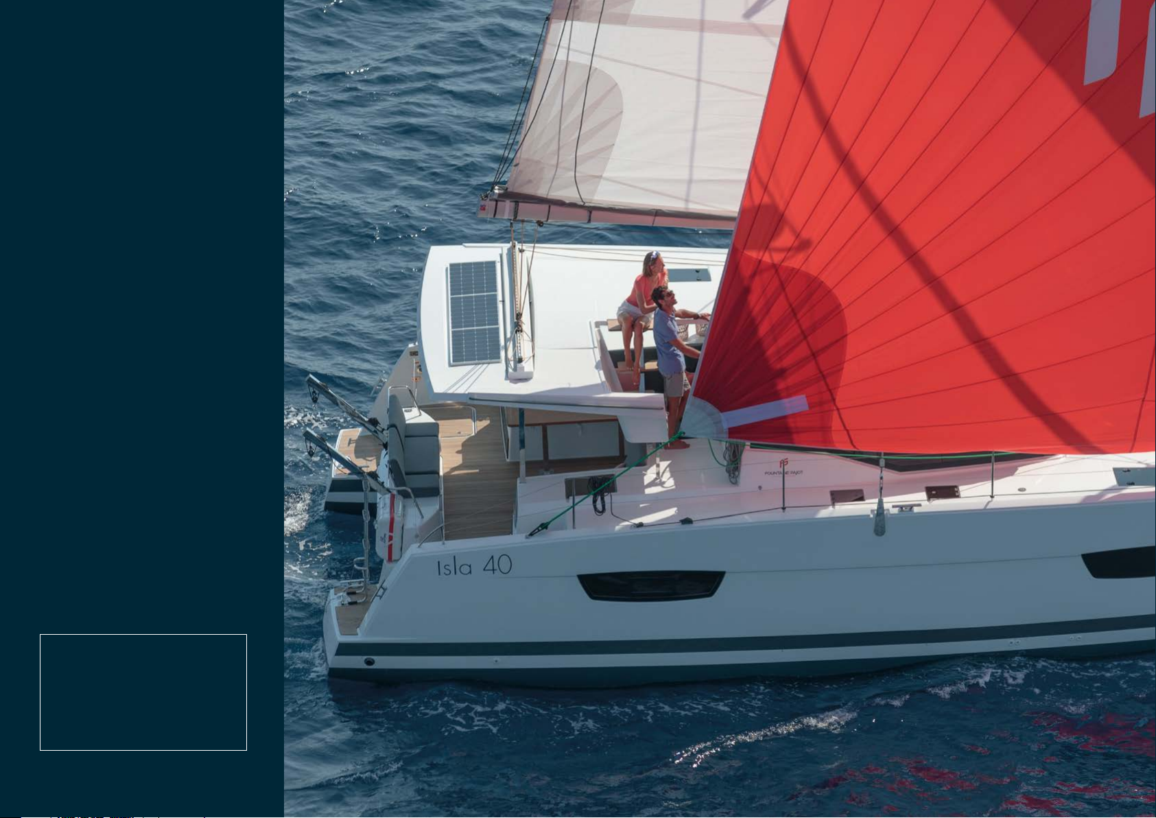
Fountaine Pajot ISLA 40 User manual

OWNER’S
MANUAL 40
ISLA

This manual has been drawn up
to help you enjoy using your craft
in complete safety. It contains the
details of the craft, the equipment
supplied or fitted, its installation
and information relating to use and
maintenance. Please
read it carefully and familiarise
yourself with the boat before using it.
If this is your first boat or if you have
changed to a type of boat that you
are not familiar with, for your comfort
and safety ensure that you acquire
expe-rience in handling and using the
boat before taking command of it.
Your dealer,
national sailing federation or yacht
club will be very happy to advise you
on local sailing schools or competent
instructors.
KEEP THIS MANUAL IN A SAFE
PLACE AND HAND IT OVER TO
THE NEW OWNER
IF YOU SELL THE BOAT.
It consists of 3 booklets:
USER GUIDE
SAFETY INFORMATION
LISTE OF DRAWINGS

Contents
1Technical specification page 5 /
V Manufacturer’s plate 6
V Identity sheet 6
V Design category 6
V Characteristics 7
2Sailing page 9 /
V Entrance door 10
V Leaving the harbour 10 - 12
V Starting the engines 13 - 14
V Sailing 15 - 16
V Arriving in a harbour 17
V Anchorage 17 - 18
V Mooring and towing 19
3Equipments page 21 /
VDeck 22 - 24
V Hull/saloon 25 - 29
4Systems page 31 /
V Steering system 32
V Electricity 33 - 37
V Gas circuit 38 - 39
V Water 40 - 46
5Manoverboard prevention 5
and man recovery page 49 /
6Fire protection page 53 /
Preparing the winter season
7& Handling page 57 /
VWater circuit 58
V Outside 58
V Engines 58
V Preparation 58
V Craning 58
8Maintenance page 61 /
V Drainage 62
V Running rigging, sheets and ropes 63
V Periodic maintenance chart 64 - 66

ISLA
40

1
Technical
Specifications
V Manufacturer’s plate .......................................................6
V Identity sheet......................................................................6
V Design category.................................................................6
V Characteristics ...................................................................7

OWNER MANUAL / ISLA 40
Technical Specifications
6
DESIGN CATEGORIES NAVIGATION TYPE WIND FORCE
(BEAUFORT SCALE) WIND SPEED WAVE HEIGHT TO TAKE INTO
CONSIDERATION
A Ocean-going > 8 ≤ 28 m/s > 4 m
BOff the coast ≤ 8 ≤ 21 m/s ≤ 4 m
CNear the coast ≤ 6 ≤ 17 m/s ≤ 2 m
DProtected water ≤ 4 ≤ 13 m/s ≤ 0,5 m
DESIGN CATEGORY
MANUFACTURER’S PLATE IDENTITY SHEET
Your ISLA 40 belongs to the « OCEAN-GOING » category (category A).
Apleasure boat of design category A is considered as designed for winds which
can exceed force 8 (in the Beaufort scale) and for waves which can exceed a
heightof 4metres, excluding exceptional conditions such as thunderstorms, violent
storms, tornadoes and extreme maritime conditions or huge waves.
Be very careful before going to sea. Fountaine Pajot cannot guarantee the perfect
ope-ration of the boat in exceptional sea conditions (violent storms, hurricanes,
cyclones, tornadoes, etc.)
The ISLA 40 is a boat susceptible to capsize and to stay inverted if there are exces-
sive sails. This is why it is important to respect the sail reduction table.parfait
fonctionnement du navire dans des conditions de mer exceptionnelles (orage violent,
ouragan, cyclone, trombe...).
1
CIN NUMBER 057
BUILDER
FOUNTAINE PAJOT
Zone industrielle
17 290 Aigrefeuille d'Aunis
TYPE OF BOAT CATAMARAN
SERIES ISLA
Risk of capsizing!
People in the cabin can
be trapped.

OWNERS MANUAL / ISLA 40 7
CHARACTERISTICS
General
LENGTH (LH) 11,925 m / 39,1 ft
HULL WIDTH (BH) 6,63 m / 21,7 ft
DRAUGHT 1,20m / 4,1 ft
AIR DRAUGHT 19,45 m / 63,8 ft
LIGHT DISPLACEMENT 9 525 kg
MAXIMUM LOAD DISPLACEMENT 12 970 kg
The maximum load recommended includes the weight of all members on board, the provisions and personal
belongings, all equipment not included in the weight of the light displacement of the boat, the cargo and the
all consumable liquids (water, fuel, etc.)
Weight
DESIGNATION WEIGHT
Fuel weight 255 kg – 300 L
Fresh water weight 530 kg – 530 L
Black and grey water weight 180 kg
Liquids total weight 965 kg
Surface of sails
MAINSAIL GENOA GENAKER (OPTIONAL)
58 m2/ 624,3ft237 m2/ 398,26 ft268 m2/ 233,09 ft2
Inboard engines
BRAND REFERENCE POWER CRUISING RATE MAX. RATE
Volvo D1-20 2x20 cv / 2x13,8 kW 2 300 tr/min 3 000 tr/min
Volvo D1-30 2x30 cv / 2x20,9 kW 2 300 tr/min 3 000 tr/min
Yanmar 3YM20 220 cv / 2x13,8 kW 2 200 tr/min 3 200 tr/min
Yanmar 3YM30 AE 2x30 cv / 2x20,9 kW 2 000 tr/min 3 200 tr/min
Electricity
STARBOARD ENGINE/
SERVICE BATTERY PACK 12 V 3 x 115 Ah + 1 x 115 Ah (Optional)
PORT ENGINE BATTERY PACK 12 V 1 x 50 Ah
Dinghy
MAXI DINGHY LENGTH 3,10 m
MAX. LOAD PER DAVIT 100 kg
Life raft
MAX. LIFE RAFT DIMENSIONS 800 x 500 x 310 cm

ISLA
40

Sailing
V Entrance door .................................................................. 10
V Leaving the harbour ...........................................10 - 12
V Starting the engines ........................................... 13 - 14
V Sailing........................................................................15 - 16
V Arriving in a harbour........................................................ 17
V Anchorage................................................................17 - 18
V Mooring and towing ........................................................19
2

OWNER MANUAL / ISLA 40
10
ENTRANCE DOOR
LEAVING THE HARBOUR
The sliding door used as the entrance door has a locking system in the open
posi-tion. It is possible to lock it from the inside with a latch on the frame.
The locking from the outside is done with a 1/4 turnkey.
Close all the hull portholes (safety hatches included), covers, deck hatches
and windscreen panels.
The safety hatches are mentioned « NEVER OPEN WHEN SAILING »
always respect this warning. Sailing means that the boat is neither
anchored, moored or grounded.
Unlock all the doors and lockers. Then check that the bilges are empty
of water.
Check that the life raft is installed (accessible at the starboard aft of the
cockpit) and hang outside the security fittings (buoy…). A second life raft
can be installed at the port aft of the cockpit.
Sailing 2
1
2
3

OWNERS MANUAL / ISLA 40 11
Connect engines circuit breakers (port and starboard engine compartments) and check that the windlass circuit breaker and the service circuit breaker are switched on.
5
b VThe diesel tank from the deck filler on the port
aft locker of the cockpit.
a VStarboard battery circuit breaker
b VService circuit breaker
c V Windlass circuit breaker
d VPort battery circuit breaker
a VThe fresh water tanks from the starboard front
deck filler.
Filling:
4
a
b
a
c
b
d
All versions
GUIDA PER L’UTENTE / LUCIA 40 11
Collegare gli staccabatterie motore (vano motore sinistro e tribordo) e verificare che l’interruttore verricello e l’interruttore ausiliario siano accesi.
5
b V I serbatoi di carburante dal tappo di rifornimento
posizionato sul gavone di poppa del pozzetto lato
sinistro.
a V I serbatoi d’acqua dolce dal tappo di rifornimento
collocato verso prua della coperta a dritta.
Riempire :
4
a VValvola di sicurezza a dritta
b VValvola di sicurezza ausiliarie
c VInterruttore verricello
d VValvola di sicurezza a sinistra
a b
a
b
a
c
b
d
Tutte le versioni
c d
a b
v1_gdu_LUCIA_IT_2018.indd 11 05/02/2018 16:14

OWNER MANUAL / ISLA 40
12
Check the water and diesel levels n the dashboard (« Navigation instr » switch on the electrical
panel).
Check that there are no fuel or gas vapours inside the engine compartments.
Switch on the electronic appliances on the electrical panel (a).
Check that the switch for the bilge pumps, at the electrical panel, is in the position “AUTO”.
Open all gas valves (bottle (d) and appliances (b))
Open the diesel tanks valves c). Located under the bed frame on the aft.
Check the navigation lights work before night sailings:
VMast (e)
In strong winds, fix all mobile elements.
Sailing 2
6
12
13
11
10
7
8
9
LEAVING THE HARBOUR (NEXT)
a VElectrical panel
b VGas valves
c VDiesel valves
d VGas locker
e VMast
c d
b
a
b
All versions
a
MANUEL PROPRIÉTAIRE / LUCIA 40
12
Vérifier les niveaux d’eau et de gasoil au tableau de bord (interrupteur « Instruments de navigation » sur
le tableau électrique).
Vérifier l’absence de vapeur de combustible et de gaz à l’intérieur des soutes moteur.
Allumer les fonctions souhaitées au tableau électrique (a).
Vérifier que l’interrupteur des pompes de cale, au tableau électrique, est en position “AUTO”.
Ouvrir tous les robinets d’alimentation gaz (côté bouteille (d) et côté appareils (b)).
Ouvrir les vannes du réservoir de gasoil (c). Elles sont situées sous le plateau de lit de cabine arrière
bâbord.
Vérifier le fonctionnement des feux de navigation avant les voyages de nuit :
V Mât (e)
Par vent fort, fixer tous les éléments mobiles.
Navigation 2
6
12
13
11
10
7
8
9
DÉPART DU PORT (Suite)
a VTableau électrique
b VRobinets gaz
c VVannes gasoil
d VCoffre gaz
e VMât
c d
b
a
b
Toutes versions
c
a
d
e
v1_gdu_LUCIA_FR_2018.indd 12 05/02/2018 16:12
d
e
c

OWNERS MANUAL / ISLA 40 13
1
3
2
Check the engine and base levels every month. (See paragraph maintenance)
Check the opening of the seawater intake valve on the engine base in the engine
compartments.
Volvo engines: EVC System:
V Activate the EVC system by pressing on the ON/OFF button.
STARTING THE ENGINES
The EVC control panel cannot be
deactivated if an engine is running.
WARNING !
STOP
Pre-heating
Starter engine
launcheur
Système fault
Oil pressure
Batteries
Cooling fluid
temperature
Off
VOLVO REV COUNTER, LCD DISPLAY

OWNER MANUAL / ISLA 40
14
Common maneuvers to different engines: :
Clutch, position the lever 1/2 forward.
Start by pressing the START button and let the engines run for 5 min at 1000 rpm
(reduced speed) to warm up the engines.
Check that the cooling system is coming out of the exhaust.
Sailing 2
STARTING THE ENGINES (NEXT))
4
5
6
VNever activate the motor starter more than ten seconds to start up the
engines as water may get into the exhaust and damage the engines.
VBefore starting a sails navigation, consult the engine supplier’s manual.
VEnsure that the ventilation openings are clear.
VWhen navigating, the lever must be in neutral position (N)
WARNING
N : Neutral position F : Forward
R : Reverse
T : Acceleration
1 : Lever
2 : Clutching

OWNERS MANUAL / ISLA 40 15
Never attach on the front points but on the bowsprit.
WARNING
SAILING
Using the asymmetrical spinnaker or the genaker (optional): :
The asymmetrical spinnaker and the genaker are sails that are designed to be used in
downwind and apparent wind blow 15 knots.
They must be stored:
- In apparent winds, over 15 knots
- When docked
- When anchored
- When not used whilst sailing
Sail reduction table according to apparent wind
Beating and
close reaching
Tailwind and
broad reaching
MAXIMUM SAIL
AREA 0 – 18 knots 0 – 15 knots
MAINSAIL 1 REEF
GENOA 2/3 18 – 25 knots 15 -20 knots
MAINSAIL 2
REEF GENOA
1/2
25 – 30 knots 20 – 25 knots
Beating and
close reaching
Tailwind and
broad reaching
MAINSAIL 3
REEF GENOA
1/3
30 – 35 knots 25 – 30 knots
MAINSAIL 3
REEF GENOA
1/5
35 – 40 knots 30 – 35 knots
MAINSAIL
DOWN GENOA
1/10
> 40 knots > 35 knots

OWNER MANUAL / ISLA 40
16
Reefing
Sailing 2
SAILING (NEXT)
Automatic reef system (reef 1):
Release slightly the mainsail sheet.
Release the mainsail’s halyard to lower the tack of the reef 1 at 20cm of
the boom.
Haul up the furling line.
Haul up the mainsail’s halyard if it is necessary so that the tack point is at
10cm approximatively above the boom.
1
2
3
4
Classic reef system (reef 2 et 3):
Release the mainsail sheet.
Release the mainsail’s halyard.
Strap the tack point.
Haul up the mainsail’s halyard.
Haul up the reef.
1
2
3
4
5
The topping lift must be haul up in order to have an angle
between the boom and the mast of 90°max.
WARNING
For more information, please refer to the drawings:
- DDF_ACC_057_001
- DDF_LDV_ACC_057
- DDF_PIE_057_036

OWNERS MANUAL / ISLA 40 17
ARRIVING IN A HARBOUR
Turn-off the engines
Switch-off the engines by pushing the STOP button, then press the ON/OFF
button to deactivate the system.
Disconnect all the functions on the electrical panel.
Close all the gas supply valves (bottle and appliances).
Check that the water has been drained from the bilges.
Disconnect the battery circuit breaker when stopped for a long period.
Close the diesel tank valves when stopped for a long period.
1
2
3
4
5
6
Unhook the safety hoist.
Drop the anchor and chain to a few meters from the final length desired.
Hook the chain to the bridle snap hook available in the anchor well.
Drop the end of the length of chain desired until the anchoring tension is
picked up by the bridle.
1
2
3
ANCHORAGE
4
Start the starboard engine (1500 rpm).
The windlass is controlled using the remote control in the anchor well.
Setting up the anchor
4
13
Always let the engines run idle for a few minutes before shutting them
down completely.
WARNING

OWNER MANUAL / ISLA 40
18
Sailing 2
Start the starboard engine.
Raise the anchor to the bridle snap hook and undo the snap hook from the
bridle.
When raising, check that the chain enters the well properly in order to avoid
the chain blocking.
Raise the anchorage slowly, checking that the anchor is placed correctly in its
davit.
When the anchor is close to the davit, check that the tip moves into the roller
in the right direction.
Block the chain by pulling hard on the security hoist: this will jam the anchor
on the davit and prevent it to damage davit or hulls.
Clamp the hoist to avoid the anchor moving on the davit.
1
2
3
4
5
6
7
Raising the anchor
During the operation, stay away from the windlass and the chain and
make sure that you protect your hands and feet.
Keep an eye whilst rising the chain in order to not damage the hull.
WARNING
If the force required by the windlass is too important, the breaker is
triggered. Reset it to restart the windlass (accessible in starboard
engine compartment).
WARNING
ANCHORAGE (NEXT)

OWNERS MANUAL / ISLA 40 19
MOORING AND TOWING
For mooring, the anchor points are the 6 cleats (a) :
- 2 x front
- 2 x middle
- 2 x aft
a VMooring cleats
The cleats have a resistance of around 6000kg. They are designed for a Ø18
polya-mide rope.
For towing, use the 2 front cleats to attach a Ø18 polyamide rope like a snap rope.
a
a
a
a
a
a

ISLA
40
Table of contents
Other Fountaine Pajot Boat manuals

Fountaine Pajot
Fountaine Pajot ATHENA 38 User manual

Fountaine Pajot
Fountaine Pajot Saba 50 User manual

Fountaine Pajot
Fountaine Pajot Helia 44 2019 User manual

Fountaine Pajot
Fountaine Pajot SUMMERLAND 40 LC User manual

Fountaine Pajot
Fountaine Pajot Lucia 40 User manual

Fountaine Pajot
Fountaine Pajot Helia 44 2013 Maple Cookie User manual

Fountaine Pajot
Fountaine Pajot ELBA 45 User manual