Fountaine Pajot Helia 44 2019 User manual

HÉLIA
44
OWNER’S
MANUAL

Contents
1Technical specifications page 5 /
V Manufacturer’s plate 6
V Identity sheet 6
V Design category 6
V Characteristics 7
2Sailing page 9 /
V Entrance door 10
V Leaving the harbour 10 - 12
V Starting the engines 13 - 14
V Sailing 15 - 16
V Arriving in a harbour 17
V Anchorage 17 - 18
V Mooring and towing 19
3Equipments page 21 /
VDeck 22 - 24
V Hull/saloon 25 - 29
4Systems page 31 /
V Steering system 32
V Electricity 33 - 35
V Gas circuit 36
V Water 37 - 45
Manoverboard prevention
5 and man recovery page 47 /
6Fire protection page 51 /
7Preparing the winter season &
Handling page 55 /
VWater circuit 56
V Outside 56
V Engines 56
V Preparation 56
V Craning 56
8Maintenance page 59 /
V Drainage 60
V Running rigging, sheets and ropes 61
V Periodic maintenance chart 62 - 64

1
Technical
Specifications
V Manufacturer’s plate.........................................................6
V Identity sheet ......................................................................6
V Design category..................................................................6
V Characteristics ....................................................................7
HÉLIA
44

OWNER’S MANUAL / HÉLIA 44 OWNER’S MANUAL / HÉLIA 44 76
Technical Specifications
DESIGN CATEGORIES NAVIGATION TYPE WIND FORCE
(BEAUFORT SCALE) WIND SPEED WAVE HEIGHT TO TAKE INTO
CONSIDERATION
A Ocean-going > 8 ≤ 28 m/s > 4 m
BOff the coast ≤ 8 ≤ 21 m/s ≤ 4 m
CNear the coast ≤ 6 ≤ 17 m/s ≤ 2 m
DProtected water ≤ 4 ≤ 13 m/s ≤ 0,5 m
DESIGN CATEGORY
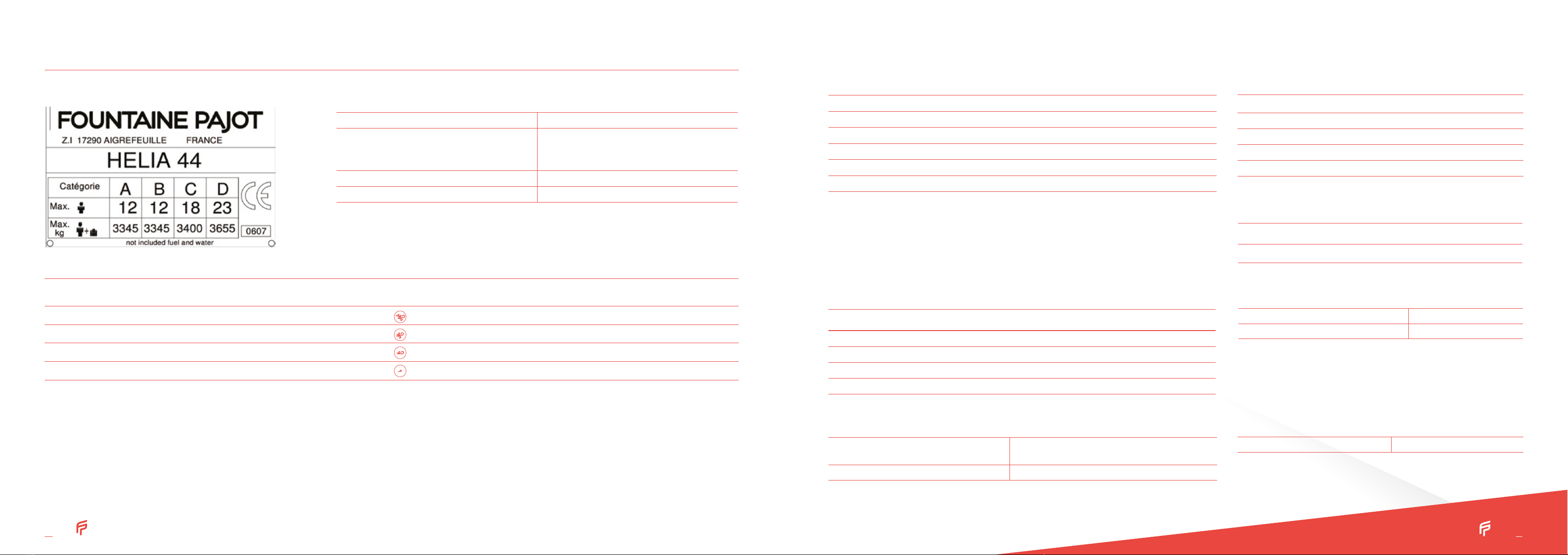
MANUFACTURER’S PLATE IDENTITY SHEET
CHARACTERISTICS
Your HÉLIA 44 belongs to the « OCEAN-GOING » category (category A).
A
pleasure boat of design category A is considered as designed for winds which can
exceed force 8 (in the Beaufort scale) and for waves which can exceed a height
of 4metres, excluding exceptional conditions such as thunderstorms, violent storms,
tornadoes and extreme maritime conditions or huge waves.
The navigation ability also depends on the crew’s skills. Their physical abilities, the
condition of the boat and hardware.
Be very careful before going to sea. Fountaine Pajot cannot guarantee the perfect ope-
ration of the boat in exceptional sea conditions (violent storms, hurricanes, cyclones,
tornadoes, etc.)
The Hélia 44 is a boat susceptible to capsize and to stay inverted if there are excessive
sails. This is why it is important to respect the sail reduction table.
General
LENGTH (LH) 13,30 m / 43,50 ft
HULL WIDTH (BH) 7,40 m / 24,3 ft
DRAUGHT 1,16 m / 3,8 ft
AIR DRAUGHT 21,65 m / 71 ft
LIGHT DISPLACEMENT 12 837 kg
MAXIMUM LOAD DISPLACEMENT 16 535 kg
The maximum load recommended includes the weight of all members on board, the provisions and per-
sonal belongings, all equipment not included in the weight of the light displacement of the boat, the cargo
and the all consumable liquids (water, fuel, etc.)
1Weight
DESIGNATION WEIGHT
Fuel weight 400 kg – 470 L
Fresh water weight 750 kg – 750 L
Black and grey water weight 180 kg
Liquids total weight 1330 kg
Surface of sails
MAINSAIL GENOA GENAKER (OPTIONAL)
70 m2/ 753,5 ft245 m2/ 484,4 ft286 m2/ 925,7 ft2
Inboard engines
BRAND REFERENCE POWER CRUISING RATE MAX. RATE
Volvo D2-40 2x40 cv / 2x29,4 kW 1800 rpm 3000 rpm
Volvo D2-50 2x50 cv / 2x35 kW 2300 rpm 3000 rpm
Yanmar 4JH45CE 2x45 cv / 2x33,1 kW 2200 rpm 3000 rpm
Yanmar 4JH57C 2x57 cv / 2x40,2 kW 2200 rpm 3200 rpm
Electricity
STARBOARD ENGINE/
SERVICE BATTERY PACK 12 V 4 x 150 Ah + 1 x 150 Ah (optional)
PORT ENGINE BATTERY PACK 12 V 1 x 50 Ah
Dinghy
MAXI DINGHY LENGTH 3,40 m
MAX. LOAD PER DAVIT 100 kg
Life raft
MAX. LIFE RAFT DIMENSIONS 800 x 530 x 320 cm
CIN NUMBER 054
BUILDER
FOUNTAINE PAJOT
Industrial area
17 290 Aigrefeuille d'Aunis
TYPE OF BOAT CATAMARAN
SERIES HÉLIA

Sailing
V Entrance door.................................................................... 10
V Leaving the harbour.............................................10 - 12
V Starting the engines............................................. 13 - 14
V Sailing ........................................................................15 - 16
V Arriving in a harbour......................................................... 17
V Anchorage................................................................17 - 18
V Mooring and towing .........................................................19
2
HÉLIA
44

OWNER’S MANUAL / HÉLIA 44 OWNER’S MANUAL / HÉLIA 44 1110
ENTRANCE DOOR
LEAVING THE HARBOUR
The sliding door used as the entrance door has a locking system in the open posi-
tion. It is possible to lock it from the inside with a latch on the frame. The locking
from the outside is done with a 1/4 turnkey.
Close all the hull portholes (safety hatches included), covers, deck hatches
and windscreen panels.
The safety hatches are mentioned « NEVER OPEN WHEN SAILING »
always respect this warning. Sailing means that the boat is neither anchored,
moored or grounded.
Unlock all the doors and lockers. Then check that the bilges are empty of
water.
Check that the hatch of the life raft is unlocked and hang outside the se-
curity fittings (buoy…). A second life raft can be installed under the helm’
stairs.
Sailing 2
1
2
3
Connect engines circuit breakers (port and starboard engine compartments) and check that the windlass circuit breaker and the service circuit breaker are switched on.
5
b VThe diesel tanks from the deck fillers on the star-
board aft of the cockpit and on the port aft locker.
a VStarboard battery circuit breaker
b VWindlass circuit breaker
c VService circuit breaker
d V Port battery circuit breaker
a VThe fresh water tanks from the front port deck filler.
Filling:
4
b
a
b
a
c
b
d
All versions
bd
ac
a

OWNER’S MANUAL / HÉLIA 44 OWNER’S MANUAL / HÉLIA 44 1312
Check the water and diesel levels on the dashboard (« Navigation instruments » switch on the
electrical panel).
Check that there are no fuel or gas vapours inside the engine compartments.
Switch on the electronic appliances on the electrical panel (a).
Check that the switch for the bilge pumps, at the electrical panel, is in the position “AUTO”.
Open all gas valves (bottle (d) and appliances (b)).
Open the diesel tanks valves. Located under the bed frame of the port aft cabin.
Check the navigation lights work before night sailings:
VFront beam (e) VFly (f) VMast (g)
In strong winds, fix all mobile elements.
6
13
12
11
10
7
8
9
LEAVING THE HARBOUR (NEXT) 1
3
2
Check the engine and base levels every month. (See paragraph maintenance)
Check the opening of the seawater intake valve on the engine base in the engine
compartments.
Volvo engines: EVC System:
V Activate the EVC system by pressing on the ON/OFF button.
STARTING THE ENGINES
The EVC control panel cannot be
deactivated if an engine is running.
WARNING
a VElectrical panel
b VGas valves
c VDiesel valves
d VGas locker
e VFront beam
f VFly
g VMast
!
STOP
Pre-heating
Starter engine
launcheur
Système fault
Oil pressure
Batteries
Cooling fluid
temperature
Off
VOLVO REV COUNTER, LCD DISPLAY
Sailing 2
c d
b
a
b
d
All versions
c
a
e
g
f

OWNER’S MANUAL / HÉLIA 44 OWNER’S MANUAL / HÉLIA 44 1514
Common maneuvers to different engines:
Clutch, position the lever 1/2 forward.
Start by pressing the START button and let the engines run for 5 min at 1000 rpm (reduced speed) to
warm up the engines.
Check that the cooling system is coming out of the exhaust.
STARTING THE ENGINES (NEXT)
4
5
6
VNever activate the motor starter more than ten seconds to start up the
engines as water may get into the exhaust and damage the engines.
VBefore starting a sails navigation, consult the engine supplier’s manual.
VEnsure that the ventilation openings are clear.
VWhen navigating, the lever must be in neutral position (N)
WARNING
Never attach on the front points but on the bowsprit.
WARNING
SAILING
Using the asymmetrical spinnaker or the genaker (optional):
The asymmetrical spinnaker and the genaker are sails that are designed to be used in
downwind and apparent wind blow 15 knots.
They must be stored:
- In apparent winds, over 15 knots
- When docked
- When anchored
- When not used whilst sailing
Sail reduction table according to apparent wind
Beating and
close reaching
Tailwind and
broad reaching
MAXIMUM SAIL
AREA 0 – 18 knots 0 – 15 knots
MAINSAIL 1 REEF
GENOA 2/3 18 – 25 knots 15 -20 knots
MAINSAIL 2 REEF
GENOA 1/2 25 – 30 knots 20 – 25 knots
Beating and
close reaching
Tailwind and
broad reaching
MAINSAIL 3 REEF
GENOA 1/3 30 – 35 knots 25 – 30 knots
MAINSAIL 3 REEF
GENOA 1/5 35 – 40 knots 30 – 35 knots
MAINSAIL DOWN
GENOA 1/10 > 40 knots > 35 knots
N : Neutral position
F : Forward
R : Reverse
T : Acceleration
1 : Lever
2 : Clutching
Sailing 2

OWNER’S MANUAL / HÉLIA 44 OWNER’S MANUAL / HÉLIA 44 1716
Reefing
SAILING (NEXT)
ARRIVING IN A HARBOUR
Turn-off the engines
Switch-off the engines by pushing the STOP button, then press the ON/OFF
button to deactivate the system.
Disconnect all the functions on the electrical panel.
Close all the gas supply valves (bottle and appliances).
Check that the water has been drained from the bilges.
Disconnect the battery circuit breaker when stopped for a long period.
Close the diesel tank valves when stopped for a long period.
1
2
3
4
5
6
Automatic reef system (reef 1):
Release slightly the mainsail sheet.
Release the mainsail’s halyard to lower the tack of the reef 1 at 20cm of the
boom.
Haul up the furling line.
Haul up the mainsail’s halyard if it is necessary so that the tack point is at
10cm approximatively above the boom.
1
2
3
4
Classic reef system (reef 2 et 3):
Release the mainsail sheet.
Release the mainsail’s halyard.
Strap the tack point.
Haul up the mainsail’s halyard.
Haul up the reef.
1
2
3
4
5
The topping lift must be haul up in order to have an angle
between the boom and the mast of 90°max.
WARNING
Always let the engines run idle for a few minutes before shutting them
down completely.
WARNING
For more information, please refer to the drawings:
- DDF_ACC_054_001
- DDF_LDV_ACC_054
- DDF_PIE_054_008
Unhook the safety hoist.
Drop the anchor and chain to a few meters from the final length desired.
Hook the chain to the bridle snap hook available in the anchor well.
Drop the end of the length of chain desired until the anchoring tension is picked
up by the bridle.
1
2
3
ANCHORAGE
4
Start the starboard engines (1500 rpm).
The windlass is controlled using the remote control in the anchor well.
Setting up the anchor
Sailing 2
4
13

OWNER’S MANUAL / HÉLIA 44 OWNER’S MANUAL / HÉLIA 44 1918
MOORING AND TOWING
Start the starboard engine.
Raise the anchor to the bridle snap hook and undo the snap hook from the
bridle.
When raising, check that the chain enters the well properly in order to avoid
the chain blocking.
Raise the anchorage slowly, checking that the anchor is placed correctly in its
davit.
When the anchor is close to the davit, check that the tip moves into the roller
in the right direction.
Block the chain by pulling hard on the security hoist: this will jam the anchor
on the davit and prevent it to damage davit or hulls.
Clamp the hoist to avoid the anchor moving on the davit.
1
2
3
4
5
6
7
Raising the anchor
During the operation, stay away from the windlass and the chain and
make sure that you protect your hands and feet.
Keep an eye whilst rising the chain in order to not damage the hull.
WARNING
For mooring, the anchor points are the 6 cleats (a) :
- 2 x front
- 2 x middle
- 2 x aft
a VMooring cleats
The cleats have a resistance of around 6000kg. They are designed for a Ø18 polya-
mide rope.
For towing, use the 2 front cleats to attach a Ø18 polyamide rope like a snap rope.
ANCHORAGE (NEXT)
Sailing 2
If the force required by the windlass is too important, the breaker is
triggered. Reset it to restart the windlass (accessible in the starboard
engine compartment).
WARNING
a
a
a
a
a
a

OWNER’S MANUAL / HÉLIA 44 OWNER’S MANUAL / HÉLIA 44 2322
3
Equipments
DECK
Deck shower
The deck shower (a) is located on the port transom.
It is switched on by two valves (b) and activated by a mixer just beside it.
a VDeck shower
b VFresh water valve
b
a
All versions
a b
Solar panels (optional)
The boat can be fitted with 4 solar panels (a), fixed behind the mainsail rail, on the
bimini.
The 12V connection is done on the service battery pack (b). The solar panels are protec-
ted by a specific circuit breaker (c).
For use and maintenance, please refer to the manufacturer’s manual.
a VSolar panels
b VService battery pack
c VCircuit breaker
a
c
b
All versions
a

OWNER’S MANUAL / HÉLIA 44 OWNER’S MANUAL / HÉLIA 44 2524
DECK (NEXT)
MAINSAIL HALYARD WINCH AND GENOA SHEET WINCH
These winches are connected to the service battery pack and run on the 12V network.
The mainsail halyard winch is protected by a 120A circuit breaker and the genoa sheet
winch is protected by a 200A circuit breaker.
DAVIT WINCH
This winch is connected to the service battery pack and runs on the 12V network. It is
protected by a 120A circuit breaker.
For use and maintenance, please refer to the manufacturer’s manual.
a VGenoa winch circuit breaker
b VMainsail winch circuit breaker
c VDavit winch circuit breaker
Electric winches (optional)
3
Equipments
2-drawer galley refrigerator 190L
Check the service battery pack charge status on the battery controller at the
chart table.
Turn on the « refrigerator » switch on the electrical panel (f).
Set the cooling thermostat to the temperature required.
The fuse box is located in the aft cupboard of the starboard companionway (e).
For use and maintenance, see the manufacturer’s manual.
HULL/SALOON
If the service battery charge level is ≤ 11.7V, the refrigerator switches to safety.
Follow these instructions to minimize the 12V energy consumption:
VSet the refrigerator thermostat to the minimum necessary.
VMinimise door opening.
VKeep the refrigerator well filled.
VDefrost the refrigerator regularly.
WARNING
90L galley freezer or 130L refrigerator (optional)
Turn on the « refrigerator » switch on the electrical panel.
Set the freezer thermostat to the temperature required.
The fuse box is located in the aft cupboard of the port companionway (d).
For use and maintenance, see the manufacturer’s manual.
Additional cockpit refrigerator 75L (optional)
This is turned on via the thermostat.
Set the refrigerator thermostat to the temperature required.
The fuse box is located in the aft cupboard of the starboard companionway (e).
For use and maintenance, see the manufacturer’s manual.
a VGalley refrigerator
b VGalley optional refrigerator / freezer
c VCockpit optional refrigerator
d VCockpit (optional) and galley refrigerator fuses
e VGalley refrigerator / freezer fuse (optional)
f VElectrical panel
a
b
All versions
b
c
f
a e
d
c
All versions

OWNER’S MANUAL / HÉLIA 44 OWNER’S MANUAL / HÉLIA 44 2726
HULL/SALOON (NEXT)
Power generator (optional)
The boat can be fitted with a power generator. The power generator is powered with the
diesel tank.
The generator runs using a 12V independent battery. The battery is charged by the generator.
Switch on the generator’s switch of the circuit breaker (a) before starting it.
The generator can be started in the fore technical compartment or at the chart table in
the saloon beside the electrical panel.
The generator always has priority over the dock line.
The dock/generator switch is selected automatically.
For use and maintenance, see the manufacturer’s manual.
1
2
b VSea water valves
c VPower generator
d VControl remote
3
Equipments
The power generator must not run empty as it may destroy the pump.
WARNING a VAir conditioning station
b VControl panel
c VCircuit breakers
Air conditioning (optional)
The boat can be fitted with air conditioner. Before getting started, open the sea
water valves then check that the boat is connected to the dock or that the power
generator is running.
Each station is supplied by a specific line added on the AC network circuit breaker.
For use and maintenance, please refer to the manufacturer’s manual.
The air conditioning must not run empty as it may destroy the pumps.
WARNING
c
All versions
a
a
b
b
a
Quatuor
a
a
b
b
b
b
a
c
a
Maestro
a
b
b
b
b
a
c
a
b
For more information, please refer to the drawing DDF_ELC_054_733
b

OWNER’S MANUAL / HÉLIA 44 OWNER’S MANUAL / HÉLIA 44 2928
Heating (optional)
The boat can be fitted with a diesel heating by heat transfer fluid in option. Before getting
started, check the opening of the tank supply valve.
Switch on the heater tank via the switch on the electrical panel.
Each cabin is fitted with a control panel and can manage its heating.
For use and maintenance, please refer to the manufacturer’s manual.
a VHeater tank
b VHeater control
c VHeaters
d VHeater tank circuit breaker
e VDiesel tank deck filler
f V Diesel tank
3
Equipments
HULL/SALOON (NEXT)
Watermaker (optional)
The boat can be fitted with a watermaker, located in the fore starboard technical
compartment.
Depending on the chosen watermaker type (12V or 220V), a specific line supplies the
watermaker. This line is connected to the circuit breakers panel (12V or 110V).
For the 220V watermaker, the power generator must be running.
For use and maintenance, please refer to the manufacturer’s manual.
a VWatermaker
b V220 V circuit breakers panel
c VRemote control
d VElectrical panel
Using the watermaker at the harbor may damage filters/membranes.
The watermaker must not run empty as it may destroy the low-pressure
pump.
WARNING
b
b
c
e
c
b
b
b
c
d
c
a
f
b
c
Maestro Quatuor
d
a
d
c
b
All versions
c
b
b
c
b
b
c
d
c
a
f

V Steering system............................................................... 32
V Electricity...............................................................33 - 35
V Gas circuit..........................................................................36
V Water...................................................................... 37 - 45
Systems 4
HÉLIA
44

OWNER’S MANUAL / HÉLIA 44 OWNER’S MANUAL / HÉLIA 44 3332
Systems 4
V The steering system is a hydraulic system. Composed with a steering wheel which
thanks to the starboard actuator leads a crossbar connecting the both stock arm of
the rudder.
V Periodic check to be performed: Check the slack of the different parts (rudder head,
rudder, crossbar) and grease balls joints if necessary.
For using the tiller, release the hydraulic circuit’s actuator thanks to the “by-pass” put
in ON position. The emergency tiller is secured at the top of the port OR starboard
rudder head.
It is only designed for sailing at reduced speed in the event of damaged helm.
Automatic pilot GARMIN (optional): The boat can be fitted with an automatic pilot
GARMIN. The pilot fuse is located in the management box in the starboard engine
compartment. The fuse of the control screen at the chart table is located under the
saloon bench and the fuse of the control screen of the helm station is located in the aft
cupboard of the starboard companionway.
STEERING SYSTEM
The emergency tiller is stored in a locker and must be easy accessible in
all conditions.
WARNING
For more information, please refer to the drawing DDF_ACC_054_008
The on-board power is produced by the engine alternators (115Ah) and stored by 12V
DC batteries.
The batteries are separated into 2 separate packs:
V Starboard engine/service battery pack = 4 x 150 Ah + 1 x 150 Ah (optional)
V Port engine battery pack = 1 x 50 Ah
The port engine battery powers:
V The port engine only.
The starboard engine battery pack powers:
V The starboard engine.
V All the 12V functions on the electrical panel.
The 3 fuses panels are positioned as follows:
V 1 under the saloon bench
V 1 in the aft cupboard of the port companionway
V 1 in the aft cupboard of the starboard companionway
The content of each box is detailed on the lid.
ELECTRICITY
For more information, please refer to the drawing DDF_ELC_054_733
12V DC engines network
Battery coupling :
V The coupling between the service battery pack and the engine battery is
triggered when the voltage on one of the packs exceeds 13,2V.
V The coupling is maintained until the pack voltage falls below 12,8V.
V When the voltage is below 12,8V, the coupling is interrupted and the engine
battery is then isolated from the starboard service battery pack
V The BACKUP/START-UP circuit breaker (for right) permits the coupling of the
battery packs. If one of the engines doesn’t start, switch on the circuit breaker.
When the engine is running, switch off directly the circuit breaker.
WARNING
Backup/start-up circuit breaker

OWNER’S MANUAL / HÉLIA 44 OWNER’S MANUAL / HÉLIA 44 3534
The 220V or 110V AC network is powered by:
- Either a dock extension
- Either a power generator (optional)
The switching choice is automatic. The whole network is protected by a 30mA differential circuit breaker.
Each function is protected by a specific circuit breaker.
Connection of the dock extension:
Check the cable’s condition. If the cable is damaged, replace it with an identical cable.
Connect the dock extension by rolling it out fully or start the power generator.
Check that the current is flowing using the light indicator on the 220V unit (or 110V depending on the
chosen option).
Switch on the differential circuit breaker and the circuit breaker(s) for the function required.
Never connect an extension with a damp plug.
WARNING
220V /110V AC network (optional)
3
4
1
2
a VDock line
b V220 V circuit breakers panel
c V110 V circuit breakers panel
(depending on the chosen option )
ELECTRICITY (NEXT)
Systems 4
a VInverter charger
b VPanel control
Inverter charger 12V/220V or 12V/110V (optional)
The boat can be fitted with an inverter charger.
This inverter charger is powered with 12V by a service battery pack and protected by a circuit breakers panel.
For use and maintenance, refer to the manufacturer’s manual
During a long stop, put the loader on OFF mode on the chart table next to the
electric panel.
WARNING
All versions
b
c
a
a
b
All versions
a

OWNER’S MANUAL / HÉLIA 44 OWNER’S MANUAL / HÉLIA 44 3736
Each gas appliance has a safety system. To switch on, hold the button down.
A gas leak detector is installed in the gas locker.
When all valves are shut-off, push on the top of the detector (as on the scheme), if
bubbles appear, there is a leak in the gas circuit.
VThe bottles are butane.
VVentilate well when using the cooking hob.
WARNING
GAS CIRCUIT
Open the pressure reducer shut-off valve (pressure reducer not supplied) attached directly to the gas bottle.
Open the shut-off valves of appliances (a) to used. They are located in the kitchen cupboard, right, under the sink (valves open in the direction of the pipe).
1
2
For more information, please refer to the drawing DDF_PLB_054_870
Systems 4Fresh water circuit
WATER
Open circuit’s main valve for the tanks to supply the water circuit (accessible in the fore cupboard of the port companionway).
Check that the hot water tank supply valve (a) is open at all times.
Switch on the fresh water pump function on the electrical panel.
1
2
3
For more information, please refer to drawings DDF_PLB_054_803 and
DDF_PLB_054_801. The hot water tank must not run empty.
WARNING
a VHot water tank
ba
a
b
a
All versions
Gas leak detector
a
a VGas valves
b VGas locker

OWNER’S MANUAL / HÉLIA 44 OWNER’S MANUAL / HÉLIA 44 3938
Sea water circuit (optional)
The boat can be fitted with an optional sea water circuit which supplies the kitchen sink and the
anchor well with sea water.
Process :
Open the sea water intake valve located at the bottom of the port staircase. (the floor hatches
open using suction cups.)
Switch on the sea water pump function on the electrical panel at the chart table.
1
2
WATER (NEXT)
Seawater intake valve
Systems 4Using the toilets
The toilets are fitted with a holding tank.
MANUAL WC
The evacuation valve must be closed while in the harbour.
Check that the sea water intake valves are opened (the floor hatches open
using suction cups).
Set the WC lever into « water intake » position.
Pump at least 10 times to flush and dilute the black water.
Set the WC lever into « flushing » position.
Pump a few times to empty the bowl completely.
Repeat the operation at least twice.
1
2
3
4
5
6
7
Evacuation valve Seawater intake valve WC lever into position « flushing »
WC lever into position « water intake »
1 2
5
3
Table of contents
Other Fountaine Pajot Boat manuals

Fountaine Pajot
Fountaine Pajot ELBA 45 User manual

Fountaine Pajot
Fountaine Pajot ATHENA 38 User manual

Fountaine Pajot
Fountaine Pajot Helia 44 2013 Maple Cookie User manual

Fountaine Pajot
Fountaine Pajot ISLA 40 User manual

Fountaine Pajot
Fountaine Pajot SUMMERLAND 40 LC User manual

Fountaine Pajot
Fountaine Pajot Saba 50 User manual

Fountaine Pajot
Fountaine Pajot Lucia 40 User manual