Four Audio DBS1 User manual

DBS1
User Manual
Version 1.2.0
2016-02-18
© Four Audio GmbH & Co. KG 2016
This manual can be downloaded from
www.fouraudio.com/en/products/dbs1.html

Content
1. Important Safety Information............................................................................................................................................3
2. EC Declaration of Conformity ............................................................................................................................................4
3. Package contents ...............................................................................................................................................................5
4. Product Specifications........................................................................................................................................................6
4.1. Connectors ................................................................................................................................................................6
4.2. Audio Performance ...................................................................................................................................................6
4.3. Dimensions and weight.............................................................................................................................................6
5. DBS1 Inputs/ Outputs.........................................................................................................................................................7
5.1. Analog Inputs.............................................................................................................................................................7
5.2. Analog Outputs..........................................................................................................................................................7
5.3. Ethernet connector ...................................................................................................................................................7
5.4. Power Supply jack .....................................................................................................................................................7
6. Usage...................................................................................................................................................................................8
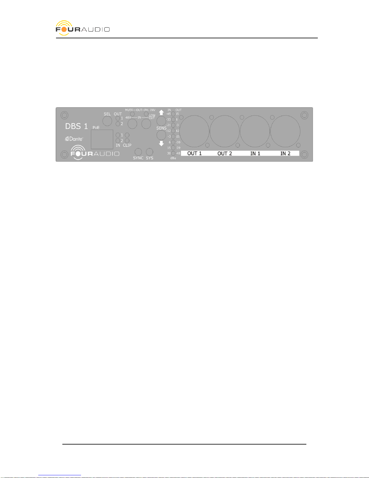
6.1. LEDs............................................................................................................................................................................8
6.2. Push Buttons .............................................................................................................................................................8
6.3. Channel selection ......................................................................................................................................................9
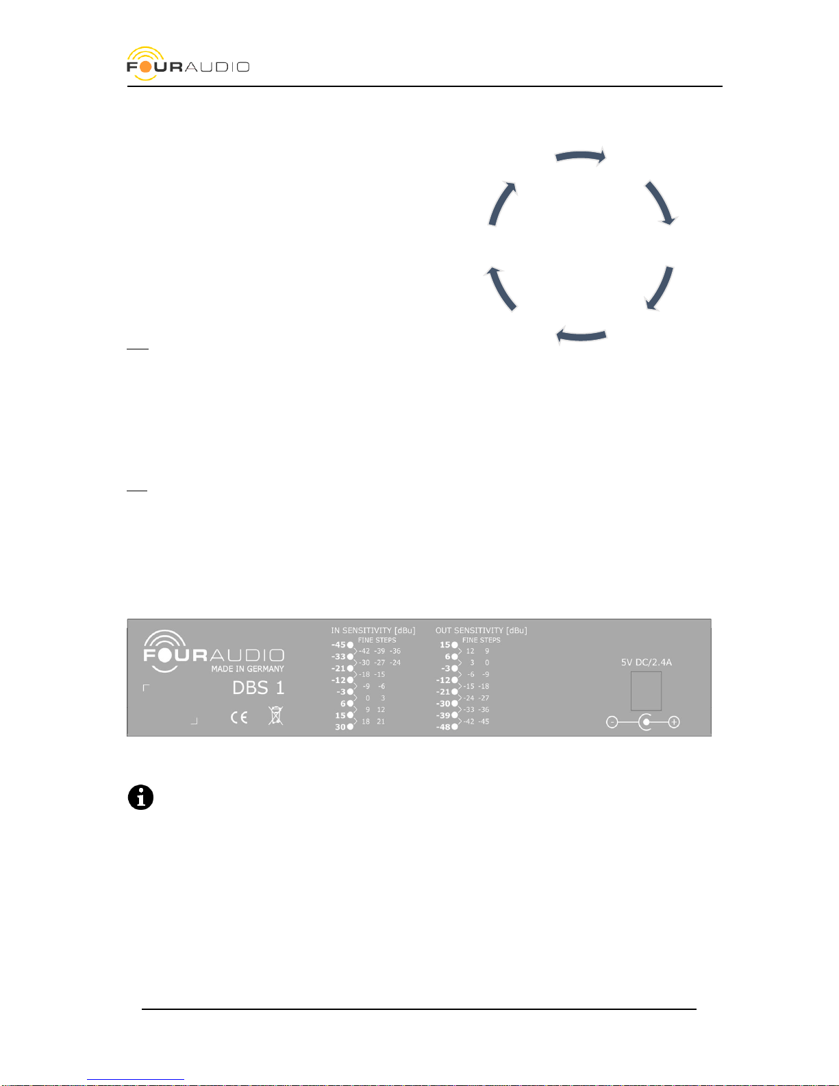
6.4. Sensitivity...................................................................................................................................................................9
6.5. Function switches................................................................................................................................................... 12
6.6. Dante® status ......................................................................................................................................................... 12
6.7. Remote Control ...................................................................................................................................................... 12
6.8. Dante® settings ...................................................................................................................................................... 12
7. Network Setup................................................................................................................................................................. 13
8. Mounting options............................................................................................................................................................ 14
9. Firmware Update............................................................................................................................................................. 15
9.1. DBS1 Software and firmware ................................................................................................................................ 15
9.2. Dante® Firmware Update Manager ...................................................................................................................... 15
9.3. Dante® Controller................................................................................................................................................... 15
9.4. Performing the preparatory Ultimo update for old Dante Software versions ................................................... 15
9.5. DBS1 controller firmware update ......................................................................................................................... 16
9.6. Final Ultimo Update ............................................................................................................................................... 16
10. Troubleshooting and FAQ .......................................................................................................................................... 17
10.1. Dante® firmware update fails............................................................................................................................... 17
10.2. Network Troubleshooting...................................................................................................................................... 18
10.3. General FAQ ........................................................................................................................................................... 19
11. Document revision history ......................................................................................................................................... 20
12. contact......................................................................................................................................................................... 21

Date: 2016-02-18
DBS1 user manual
3
1. Important Safety Information
This device has been manufactured and tested with your safety in mind. However, improper use can result in
potential electric shock or fire hazards.
To avoid defeating the safeguards that have been built into the device, please observe the precautions discussed
in this document.
Warnings on the external power supply
The lightning flash with arrowhead symbol, within a triangle, is intended to alert you to the presence of
uninsulated “dangerous” voltages within your device’s enclosure that may be of sufficient magnitude to
constitute a risk of electric shock to persons.
The exclamation point within a triangle is intended to alert you to the presence of important instructions in the
literature accompanying the device.
Other warnings
TO REDUCE THE RISK OF ELECTRIC SHOCK, DO NOT REMOVE THE COVER OF THE DEVICE.
THERE ARE NO USER-SERVICEABLE PARTS INSIDE IT.
TO REDUCE THE RISK OF FIRE OR ELECTRIC SHOCK, DO NOT EXPOSE THIS DEVICE TO RAIN OR MOISTURE.
DO NOT PERFORM ANY SERVICING UNLESS YOU ARE QUALIFIED TO DO SO BY FOUR AUDIO.
REFER ALL SERVICING TO QUALIFIED SERVICE PERSONNEL.
SERVICING THE DEVICE YOURSELF WILL INVALIDATE THE WARRANTY.
Ventilation
Slots and openings in the casing of the device are provided for ventilation, to ensure reliable operation of the
device and to protect it from overheating.
Never block the ventilation openings by placing the device on a bed, sofa, rug or other similar surface;
Never cover the ventilation openings with items such as newspapers, cloths etc.
Do not place the device in a built-in installation such as a bookcase or rack unless proper ventilation is provided
or you have adhered to the manufacturer’s instructions.
Water and moisture
Do not expose this device to dripping or splashing and ensure that no objects filled with liquids, such as vases,
are placed on the device
Disposal
When the end-of-life of your device is reached, do not dispose this device in the household waste. This protects
our environment and saves raw materials. Return it to your distributor who will dispose it free of charge for you.
KEEP THIS INFORMATION FOR FUTURE REFERENCE

Date: 2016-02-18
DBS1 user manual
4
2. EC Declaration of Conformity
An example of this equipment has been tested and found to comply with the following European and
international Standards for Electromagnetic Compatibility and Electrical Safety:
Radiated Emission (EU): EN55103-1 (1996)
RF Immunity (EU): EN55103-2 (1996)
Electrical Safety (EU): EN60065 (1993)
Manufacturer's Name & Address
Four Audio GmbH & Co. KG
Konrad-Zuse-Str. 4
52134 Herzogenrath
Germany
Product Name
DBS1
Aachen, Oct-31-2013
Rainer Thaden

Date: 2016-02-18
DBS1 user manual
5
3. Package contents
1x DBS1 Dante® Audio Interface
1x power supply: Meanwell GS15A-1P1J (Input 90-264 V AC, Output 5 V DC / 2,4 A)
1x Power cord (IEC-60320 C13, Type F CEE 7/4)
2x Mounting brackets (see chapter 8)
4x Adhesive feet

Date: 2016-02-18
DBS1 user manual
6
4. Product Specifications
The DBS1 is a two channel analog in / analog out Dante® interface. It is based on Audinate’s Ultimo Dante® chip
which is the entry-level Dante interface. For devices with network redundancy, please check
www.fouraudio.com for our DBO devices which are based on Audinate’s Brooklyn module.
4.1. Connectors
Analog Inputs
2 balanced XLR
Analog Outputs
2 balanced XLR
Ethernet
1 RJ-45 with Power over Ethernet, 100 MBit
Power
5V DC/2.4A
4.2. Audio Performance
Sampling rate
48 kHz / 96 kHz
Resolution
24 bit
Max. Input Level
-45 dBu - +30 dBu
Max. Output Level
-48 dBu - +15 dBu
Dynamic Range AD
115dB(A) 112 dB(lin)
Dynamic Range DA
117dB(A) 114 dB(lin)
Equivalent Input Sensitivity
-123 dBu
THD @ +15 dBu output level
-105 dB
4.3. Dimensions and weight
Width / Height / Depth
195 x 39 x 125 mm
Weight only DBS / packed with PSU
730 g / 1330 g

Date: 2016-02-18
DBS1 user manual
7
5. DBS1 Inputs/ Outputs
The DBS1 provides 2 balanced analog inputs and 2 balanced analog outputs for audio.
5.1. Analog Inputs
The analog inputs provide a dynamic range of 115 dB(A) with a maximum input voltage of 30 dBu.
Following functions are available:
Sensitivity +30 / +21 / .. / +3 / 0 / -3 /.. -42 / -45 dBu 3 dB steps
48 V Phantom Power On / Off
70 Hz / 1st order low cut filter On / Off
(Bold values are factory default)
The two input channels will appear as Channel 1 and 2 of the DBS1 device in the Dante® Controller Software.
5.2. Analog Outputs
The analog outputs provide a dynamic range of 114dB(A) with a maximum output voltage of 15 dBu.
Following functions are available:
Sensitiviy -48 dBu .. 15 dBu in 3 dB steps
Phase Invert 0° / 180°
Mute On / Off
Both output channels will appear as Channel 1 and 2 of the DBS1 device in the Dante® Controller software.
5.3. Ethernet connector
The DBS1 has one RJ-45 Ethernet connector to connect the unit to a Dante® Primary network. For information
about how to set-up a Dante® network please check Audinate’s help site and the famous Dante FAQ
https://www.audinate.com/resources/faqs
5.4. Power Supply jack
Use the supplied 5 V desktop power supply or Power over Ethernet (PoE).
The external power supply and PoE can be used simultaneously to achieve redundancy.
The metal bracket on the rear provides a pull relief.

Date: 2016-02-18
DBS1 user manual
8
6. Usage
The DBS1 was designed as a hassle-free plug-and-play device. This chapter describes all buttons and LEDs to
ensure you’ll get the most out of your Dante® Breakout box.
On the Front panel you’ll find all controls and LEDs which are explained below. The function of some elements
can change depending on whether an input or an output is selected.
6.1. LEDs
Function / Meaning
OUT 1
Output 1 selected
Out 2
Output 2 selected
In 1
Input 1 selected
In 2
Input 2 selected
CLIP 1
Input 1 clipping
CLIP 2
Input 2 clipping
MUTE / 48V
Output: Mute On *
Input: Phantom Power On *
PH.INV / LOW CUT
Output: Phase Invert On *
Input: Low Cut On *
SYNC
see table below
SYS
see table below
LINK
Ethernet connection established
ACT
blinks on network activity
SENS (8 LEDs)
see table below
* The LEDs MUTE/48V and PH.INV/LOW CUT show the state of this function for the selected channels.
6.2. Push Buttons
Function / Meaning
SEL
Selection of Input / Output see table below
MUTE / 48V
Output: Mute on / off
Input: toggle Phantom power on / off
PH.INV / LOW CUT
Output: Phase inversion on / off
Input: Low Cut on / off
UP
Input: increase sensitivity
Output: increase output level
DOWN
Input: decrease sensitivity
Output: decrease output level

Date: 2016-02-18
DBS1 user manual
9
6.3. Channel selection
To select the active channel use the SEL button. With each
press of a button the DBS steps through six states of
channel selection as shown on the right. The yellow
channel LEDs show the active selection.
All changes made using the remaining four functional
buttons (page 12) are applied to those channels whose
LED is lit.
The function of each key changes depending on whether
an input or an output is selected. See explanations in the
next chapters.
Hint: If two channels are selected the LEDs are showing
settings of channel 1 only! There is no indication if Ch. 2 has different settings to Ch. 1! Parameter changes are
relative to the current setting of channel 1 and copied to channel 2. Keep this in mind when different source
signals like a microphone and a line signal are connected.
6.4. Sensitivity
The front panel provides 8 LEDs which indicate the current input or output gain. As there are more than 8 steps
in gain these “fine steps” are shown as a combination of two LEDs. The tables below show the gain settings.
Info: Bold values are factory default
To change the sensitivity of a channel follow these steps:
1. Make sure the correct channel is selected. Push the SEL button until the desired channel LEDs are lit
2. Use the SENS buttons to change the output or input sensitivity according to Table 1 or Table 2
At the rear panel you’ll find a summary of both tables:
The output sensitivity indicates which analogue signal level (in Volts or dBu) is to be expected at the
maximum digital signal level (fullscale, FS) over Dante®.
The input sensitivity indicates which analogue signal level (in Volts or dBu) can be applied before the
digital maximum level (fullscale) is reached. Never exceed this level because this will lead to distortions!
Outputs
1+2
Inputs
1+2
Output 1Output 2
Input 1
Input 2

Date: 2016-02-18
DBS1 user manual
10
Table 1 output sensitivities
Step
LEDs lit
Fullscale Output level
[dBu]
Veff
Vpeak
1
15
15
4,36 V
6,16 V
2
6 & 15
12
3,08 V
4,36 V
3
6 & 15
9
2,18 V
3,09 V
4
6
6
1,55 V
2,19 V
5
-3 & 6
3
1,09 V
1,55 V
6
-3 & 6
0
775 mV
1,10 V
7
-3
-3
548 mV
776 mV
8
-12 & -3
-6
388 mV
549 mV
9
-12 & -3
-9
275 mV
389 mV
10
-12
-12
195 mV
275 mV
11
-21 & -12
-15
138 mV
195 mV
12
-21 & -12
-18
97,5 mV
138 mV
13
-21
-21
69,0 mV
97,6 mV
14
-33 & -21
-24
48,9 mV
69,1 mV
15
-33 & -21
-27
34,6 mV
48,9 mV
16
-30
-30
24,5 mV
34,6 mV
17
-33 & -36
-33
17,3 mV
24,5 mV
18
-33 & -36
-36
12,3 mV
17,4 mV
19
-39
-39
8,69 mV
12,3 mV
20
-39 & -48
-42
6,15 mV
8,70 mV
21
-39 & -48
-45
4,36 mV
6,16 mV
22
-48
-48
3,08 mV
4,36 mV

Date: 2016-02-18
DBS1 user manual
11
Table 2 input sensitivities
Step
LEDs lit
Input Sensitivity [dBu]
Veff
Vpeak
1
-45
-45
4,36 mV
6,16 mV
2
-45 & -33
-42
6,15 mV
8,70 mV
3
-45 & -33
-39
8,69 mV
12,3 mV
4
-45 & -33
-36
12,3 mV
17,4 mV
5
-33
-33
17,3 mV
24,5 mV
6
-33 & -21
-30
24,5 mV
34,6 mV
7
-33 & -21
-27
34,6 mV
48,9 mV
8
-33 & -21
-24
48,9 mV
69,1 mV
9
-21
-21
69,0 mV
97,6 mV
10
-21 & -12
-18
97,5 mV
138 mV
11
-21 & -12
-15
138 mV
195 mV
12
-12
-12
195 mV
275 mV
13
-12 & -3
-9
275 mV
389 mV
14
-12 & -3
-6
388 mV
549 mV
15
-3
-3
548 mV
776 mV
16
-3 & 6
0
775 mV
1,10 V
17
-3 & 6
3
1,09 V
1,55 V
18
6
6
1,55 V
2,19 V
19
6 & 15
9
2,18 V
3,09 V
20
6 & 15
12
3,08 V
4,36 V
21
15
15
4,36 V
6,16 V
22
15 & 30
18
6,15 V
8,70 V
23
15 & 30
21
8,69 V
12,3 V
24
30
30
24,5 V
34,6 V

Date: 2016-02-18
DBS1 user manual
12
6.5. Function switches
The two function buttons MUTE/48V and PH.INV/LOW CUT have different functions depending on whether an
input or an output was selected:
switch
In-/out
function
MUTE/48V
OUTPUT
toggles mute ON and OFF
PH.INV/LOW CUT
OUTPUT
toggles phase inversion ON and OFF
MUTE/48V
INPUT
toggles 48V phantom power ON and OFF
PH.INV/LOW CUT
INPUT
toggles the analogue low cut filter ON and OFF
6.6. Dante® status
The status of the Dante® interface is displayed with LEDs SYNC and SYS as shown in table below.
Color
Description
SYS red
System booting
SYS green
System ready
SYNC amber
PTP currently syncing
SYNC red
PTP error / no PTP sync / PTP disabled
SYNC green
PTP slave, with PTP sync
SYNC green flashing
PTP master
SYS & SYNC flashing green
Identify
SYS & SYNC flashing amber
Firmware upgrade in progress
SYS & SYNC flashing red
Failsafe –corrupt or missing application image
Note: PTP = Precision Time Protocol (One device in the Dante® audio network is the Dante® clock master. All
other devices are Dante® clock slaves synchronized by PTP.)
6.7. Remote Control
All functions of the DBS1 can be remote controlled by the Four Audio DBS1 software. Please check at
http://fouraudio.com/en/downloads.html
6.8. Dante® settings
All Dante® features are configured and monitored in Dante® Controller which is the software application
provided by Audinate, the inventor of Dante®. Dante® Controller and its user manual can be downloaded from
Audinate’s homepage. Make sure to use latest version of Dante® Controller which is 3.6 or later.
https://www.audinate.com/products/software/dante-controller
If you are not familiar to the Dante® Audio network we strictly recommend to read the user manual of the Dante®
Controller software first and check the FAQ.
https://www.audinate.com/resources/faqs

Date: 2016-02-18
DBS1 user manual
13
7. Network Setup
A Dante®- device that is connected to a network will automatically set up its network configuration including IP
address settings.
On a network with DHCP server, which may be the case for installed networks, the DBS1 will receive an IP
address using the standard DHCP protocol.
On a network without DHCP server, which may be the case for temporary or smaller networks, the Dante®-
device will automatically assign itself an address using link local protocols, in the same way PCs and printers
often do.
If you directly connect the DBS1 to your computer, both devices will automatically negotiate their IP addresses
using link local protocol. Alternatively, you can run a DHCP service on your computer to assign an IP address to
the DBS1 and to your computer.
Please also check the official Dante® Controller User Guide at
http://dev.audinate.com/GA/dante-controller/userguide/pdf/latest/
Once the DBS1 is correctly integrated in your network, you can change its IP settings in the Dante® controller
software.

Date: 2016-02-18
DBS1 user manual
14
8. Mounting options
There are several possibilities to put the DBS1 to where you want it to be:
For free-standing on your desk use the supplies adhesive feet
On the bottom, you’ll find four holes which can be used to screw the DBS1 to a rack tray. Use 3 mm
screws which are no longer than 5 mm.
The brackets supplied with the unit can be mounted in two positions for rack mounting and surface
mounting. Attach the brackets using three screws on each side as shown on the pictures
Use the coupler to mount two units in a 19” rack.
1. 195 mm width rack mount1
2. Mounting on flat surface
3. Two devices in one 19” 1 RU
1
Please note that the DBS1 was designed to have dimensions as small as possible. Thus its height is lower than 1 RU and its
width smaller than 9,5”

Date: 2016-02-18
DBS1 user manual
15
9. Firmware Update
To update the DBS1 firmware, follow the instructions below. Please make sure you have a reliable power supply
and network connection.
The DBS1 contains two central chips: The Dante® Ultimo chip and a controller chip by Four Audio. Therefore, the
update requires multiple steps. The first step is a preparatory update for the Ultimo chip. Then, update the DBS1
controller chip and finally install the latest Ultimo firmware.
To update the Dante® Ultimo firmware, third party software from Audinate has to be used.
Please follow exactly the steps described here. Do NOT just update the Dante® Ultimo firmware
without also updating the Four Audio firmware, as this will lead to malfunction.
9.1. DBS1 Software and firmware
Download and install the latest DBS1 Software from http://four-audio.com/en/downloads.html.
Download the latest set of firmware files http://four-audio.com/data/latest_dbs_firmware.php and unzip it:
DBS1_ult-preparatory.dnt (preparatory firmware for Dante® Ultimo chip)
DBS1_<version>.fwu (firmware for Four Audio Controller chip)
DBS1_ult-<version>.dnt (firmware for Dante® Ultimo chip)
README.txt (update instructions)
9.2. Dante® Firmware Update Manager
Download and install the latest Dante® Firmware Update Manager (v.1.4.16.6 or later) from Audinate.
https://www.audinate.com/products/firmware-update-manager
9.3. Dante® Controller
Download and install the Dante® Controller.
You’ll find it under https://www.audinate.com/products/software/dante-controller
It is strictly recommended to disconnect audio output or turn off connected devices during the update
procedure because loud click noise can occur!
9.4. Performing the preparatory Ultimo update for old Dante
Software versions
Because of major changes in the Ultimo and Four Audio
Controller firmware, a preparatory Ultimo firmware update
is required if the Ultimo firmware is lower than 2.2.3.1.
Open the Dante® Firmware Update Manager, select your
network, and then choose Update Dante Firmware. Load the
DBS1_ult-preparatory.dnt firmware file. The Update Manager
will scan for your DBS1 devices.

Date: 2016-02-18
DBS1 user manual
16
If the displayed Ultimo Software Version of your device is lower than 2.2.3.1, you need the preparatory update
(otherwise go to 9.5 directly).
Select the device and click Start in order to upgrade to the preparatory Ultimo software.
Restart the DBS1.
After the update, the Ultimo Software Version will be
2.0.0.9. Even if it was the same number before, the
update has worked. Inside the Dante Controller, you
can verify that the Device Firmware Version has
changed to 15.11.5.
9.5. DBS1 controller firmware update
Start the Four Audio DBS1 software. If you have several
network cards installed in your computer, choose the correct
network interface. In the list displaying the DBS1 units found
in the network select the device that is to be updated.
The status bar shows the version of the Four Audio
Controller Firmware.
Now go to Device => Firmware Update browse to
DBS1_<version>.fwu. Open starts the firmware update.
During the update process, you can hear relays clicking inside
the DBS1.
After closing the Update dialog and pressing 'Refresh' the status bar shows the new firmware version.
9.6. Final Ultimo Update
Update the Ultimo chip with Dante® Firmware Update
Manager to version DBS1_ult-<version>.dnt.
Congratulations, your DBS1 is up-to-date now.
In Dante® Controller you should find your device with the
latest Firmware versions now:

Date: 2016-02-18
DBS1 user manual
17
10. Troubleshooting and FAQ
10.1. Dante® firmware update fails
If the Dante® firmware update failed, the Dante® Firmware
Update Manager reports an error message like shown on the
right and the SYNC and SYS LEDs of DBS1 are flashing red. The
Dante® Controller reports that the device has entered failsafe
mode.
To solve this issue, the DBS1 needs a static IP address for the
firmware update even if it is running in a network with DHCP
server or local link configuration.
Follow these steps:
1. Power cycle the DBS1. It will start with the previous firmware.
2. Choose two IP addresses within the same subnet.
3. Connect the DBS1 directly to the network socket of the computer.
4. In Dante® Controller set the IP of the DBS1 to one of those addresses and press ‘Apply’.
5. Set the IP of the computer to the other IP address as chosen above.
6. Perform the upgrade again
7. Restore the original network settings on the DBS1 and the computer
Hint: To simplify step 2 to 5, you can temporarily assign the same IP address to the DBS1 that it had been given
by the DCHP server before and leave it on the network. Restore settings after the update.
How do I read the current IP address of my DBS1?
Open Dante® Controller and read the current IP address from
Device view => Status.
How do I change the IP settings of my DBS1?
Open Dante® Controller and go to the Network Config Tab in
the Device view

Date: 2016-02-18
DBS1 user manual
18
I have upgraded the chips in the wrong order and the DBS1 does not appear in DBS1 software
Flash the firmware DBS1_ult-2.0.0.9_5B05.dnt with Dante® Firmware Update Manager to the Dante® Ultimo
chip and start the upgrade procedure again.
The firmware upgrade for the Four Audio controller chip does not finish
It may happen that the Ultimo chip stops to communicate with the Four Audio controller chip. In that case
turn the DBS1 off and on and start the upgrade of the Four Audio chip again.
Firmware upgrade was interrupted e.g. by loss of power or network failure
If the upgrade of the Four Audio controller was interrupted, just repeat the procedure after restarting the unit.
The unit always starts with the old firmware until the upgrade was successful.
In case the Dante® Ultimo chip update fails, see Using Failsafe Recovery in the User Manual of Dante®
Firmware Update Manager.
Other problems
See Troubleshooting in the User Manual of Dante® Firmware Update Manager
http://dev.audinate.com/GA/firmware-update-manager/userguide/latest/
10.2.Network Troubleshooting
When do I expect to have network problems?
If one or several of the following symptoms occur, we recommend checking the network configuration:
Dante® Controller shows orange “unsuccessful subscription” icons, which usually means that a device
that was present earlier is now missing
Intermittent faults, which may be heard as dropped samples or “cracks” in the audio signal
Dante® devices appear and disappear in Dante® Controller
Items in the “Device View” of the Dante® Controller are greyed out
What are possible causes for network problems?
One or several of the following items can cause connection problems:
Unplugged /badly connected or faulty Ethernet cables
Misconfigured switches
Network cables not suitable or damaged (use at least 100 Mbit CAT5 cables)
Dante® devices removed or turned off
Symptoms of switch or cabling issues
IP address conflicts or configuration issues (e.g. static IP set)
How can I fix network issues?
Go through the switch and cabling checklist
Are all the connected link/status lights on the switch lit or flashing as expected?
Are all switches powered on and show no error?
Is the cable plugged in correctly at the switch and the PC or equipment?
Is the switch configured correctly?
Perhaps QoS or VLANs have been set up incorrectly
Are you using a switch from another application with an unchecked or untested configuration?
Is there a DHCP server present in the network?
If a DHCP is used check that “obtain IP address automatically” is activated
Do other devices receive an IP address correctly? We experienced that in most cases IP address
problems cause the devices not to work properly.
Try to deactivate wireless LAN / Wi-Fi on your computer

Date: 2016-02-18
DBS1 user manual
19
Also check https://www.audinate.com/resources/networks-switches for suitable network switches
Can I use the DBS1 on a wireless network?
Audio streaming and control over wireless LAN (Wi-Fi) is intentionally blocked by all Audinate software
applications. A Dante® device will not appear in the Dante® Controller if it is connected over wireless LAN.
Do I have to deactivate my wireless LAN adaptor?
Our experience is, that Wi-Fi can be kept activated without hassle. In case of problems, especially network
problems, it is worth to check again with deactivated Wi-Fi adapter.
10.3.General FAQ
Many options, features and behaviours that a user may expect to be device specific are actually Dante® specific.
Thus, most of the following explanations are copied from the Dante® Controller user manual or online FAQ.
Consult these resources for Dante® related information:
http://dev.audinate.com/GA/dante-controller/userguide/pdf/latest/
https://www.audinate.com/resources/faqs
Why does the DBS1 not detect the sample rate automatically?
Dante® supports different sample rates simultaneously within one network. So before subscribing to a
transmitting device the sample rate needs to be selected with Dante® Controller. After that, Dante® Controller
allows subscriptions to transmitting devices running with same sample rate only.
Keep in mind that the DBS1 can receive flows from different transmitting devices and auto detection of sample
rate would fail if transmitting devices are not running with equal sample rates.
Why does the DBS1 not playback audio if connected directly to a computer with Dante® Virtual Soundcard as
external soundcard?
Dante® is an audio network, not a point to point connection. DBS1 as a receiver and/or transmitter, always
needs to be subscribed to the desired transmitter even if there is only one transmitter in the network. Audio
routes are most frequently configured using the Dante® Controller software, running on any Windows or Mac
OSX computer that is attached to the Dante® network. Dante® Controller and Dante® Virtual Soundcard can be
used on the same computer.
Dante® Controller is not displaying details under Clock Status or Device Status. What's wrong?
This symptom indicates that the Dante® services cannot communicate with the Dante®-enabled devices on the
network. This may be caused by port blockage due to protection software, or by the failure of a background
service.
On a Windows PC make sure that no third-party firewalls or Internet protection products are active on the
computer. Dante® software will automatically adjust the built-in Windows firewall.
If you have multiple network interfaces (NICs) on the computer, disable any that are not being used by
Dante®.
Check the Services application (Start Menu -> Control Panel -> Administrative Tools -> Services) to see that the
Dante® Control and Monitoring service is running. Restart this service if necessary.

Date: 2016-02-18
DBS1 user manual
20
11. Document revision history
Date
item
Version
2016-02-16
Updated document
1.2
2015-11-06
Firmware Update procedure
1.1
2013-11-14
Initial revision
1.0
Other manuals for DBS1
1
Table of contents