HBM PW29 Series User manual

Mounting Instructions | Montageanleitung |
Notice de montage
English Deutsch Français
PW29

Hottinger Baldwin Messtechnik GmbH
Im Tiefen See 45
D-64293 Darmstadt
Tel. +49 6151 803-0
Fax +49 6151 803-9100
www.hbm.com
Mat.: 7-0101.0010
DVS: A03313_02_Y00_00 HBM: public
09.2018
EHottinger Baldwin Messtechnik GmbH.
Subject to modifications.
All product descriptions are for general information only.
They are not to be understood as a guarantee of quality or
durability.
Änderungen vorbehalten.
Alle Angaben beschreiben unsere Produkte in allgemeiner
Form. Sie stellen keine Beschaffenheits- oder Haltbarkeits
garantie dar.
Sous réserve de modifications.
Les caractéristiques indiquées ne décrivent nos produits
que sous une forme générale. Elles n'impliquent aucune
garantie de qualité ou de durabilité.

Mounting Instructions | Montageanleitung |
Notice de montage
English Deutsch Français
PW29

2A03313_02_Y00_00 HBM: public PW29
English
1 Safety instructions 3........................................
2 Markings used 7............................................
2.1 The markings used in this document 7..........................
2.2 Symbols on the product 8.....................................
3 Conditions on site 8........................................
3.1 Corrosion protection 8........................................
3.2 Deposits 8..................................................
4 Mechanical installation 9....................................
4.1 Important precautions during installation 9......................
4.2 Mounting 9..................................................
5 Electrical connection 12......................................
5.1 Connection with a six‐wire configuration 12.......................
5.2 Connection with a four‐wire configuration 12......................
5.3 Shortening the cable 13.......................................
5.4 Extension cable 13............................................
5.5 Cable protection 13...........................................
5.6 EMC protection 14............................................
6 Specifications 15............................................
7 Dimensions 16..............................................

Safety instructions
PW29 A03313_02_Y00_00 HBM: public 3
1 Safety instructions
Appropriate use
Load cells of the PW29…type series are designed for technical weighing
applications within the load limits stipulated in the specifications. Any other use
is not the designated use.
Load cells must only be installed and used by qualified personnel, strictly in
accordance with the specifications and in compliance with the safety require
ments and regulations contained in these mounting instructions. It is also
essential to observe the applicable legal and safety regulations for the applica
tion concerned. The same applies to the use of accessories.
Load cells are not intended for use as safety components. Please also refer to
the section: “Additional safety precautions”. Proper and safe operation of load
cells requires appropriate transportation, correct storage, siting and mounting,
and careful operation.
Loading capacity limits
When using the load cells, it is essential to comply with the details given in the
technical data sheets. In particular, the respective maximum loads specified
must never be exceeded. The following values specified in the technical data
sheets, for example, must not be exceeded:
SLimit load
SLimit load at max. eccentricity
SLimit lateral loading
SBreaking loads
STemperature limits
SLimits of electrical loading capacity
When several load cells are installed in a scale, make sure that there is not
always an even distribution of load onto the individual load cells.

Safety instructions
4A03313_02_Y00_00 HBM: public PW29
Use as a machine element
Load cells can be used as machine elements. When used in this manner, it
must be noted that, to favor greater sensitivity, the load cells are not designed
with the safety factors usual in mechanical engineering. Please refer here to
the section “Loading capacity limits”, and to the specifications.
Accident prevention
The prevailing accident prevention regulations must be taken into account,
even though the maximum capacity specified in the destructive range is well in
excess of the full scale value.
Additional safety precautions
Load cells cannot (as passive transducers) implement any (safety‐relevant)
cutoffs. This requires additional components and constructive measures for
which the installer and operator of the plant is responsible.
In cases where a breakage or malfunction of the load cells would cause injury
to persons or damage to equipment, the user must take appropriate additional
safety measures that meet at least the requirements of applicable safety and
accident prevention regulations (e.g. automatic emergency shutdown, overload
protection, catch straps or chains, or other fall protection).
The layout of the electronics conditioning the measurement signal should be
such that measurement signal failure does not cause damage.
Explosion protection version option
The following also apply to the load cells supplied with this option, that are to
be used in potentially explosive atmospheres:
SIt is essential to comply with the relevant code of practice during installation.
SIn the explosion protection version, the connection cable of the single point
load cells has free ends (for the cable wire assignment, see section 5.1).
SThere must be compliance with the installation conditions cited in the Certi
ficate of Conformity and/or the Type Examination Certificate.

Safety instructions
PW29 A03313_02_Y00_00 HBM: public 5
General dangers of failing to follow the safety instructions
Load cells are state‐of‐the‐art and reliable. There may be risks involved if the
transducers are mounted, sited, installed and operated inappropriately, or by
untrained personnel. Everyone involved with siting, starting up, operating or
repairing a load cell must have read and understood the Mounting Instructions
and in particular the technical safety instructions. Load cells can be damaged
or destroyed by non‐designated use of the load cells, or by non‐compliance
with the mounting and operating instructions, these safety instructions or any
other applicable safety regulations (BG safety and accident prevention regula
tions) when using the load cells. Load cells can break, particularly in the case
of overloading. The breakage of a load cell can also cause damage to property
or injury to persons in the vicinity of the load cell.
If the load cells are not deployed according to their designated use, or if the
safety instructions or specifications in the mounting and operating instructions
are ignored, it is also possible that the load cells may fail or malfunction, with
the result that persons or property may be affected (due to the loads acting on
or being monitored by the load cells).
The scope of supply and performance of the transducer covers only a small
area of weighing technology, as measurements with (resistive) strain gage
sensors presuppose the use of electronic signal conditioning. In addition,
equipment planners, installers and operators should plan, implement and
respond to the safety engineering considerations of the weighing technology in
such a way as to minimize residual dangers. Pertinent national and local regu
lations must be complied with.
Conversions and modifications
The transducer must not be modified from the design or safety engineering
point of view except with our express agreement. Any modification shall
exclude all liability on our part for any damage resulting therefrom.
Maintenance
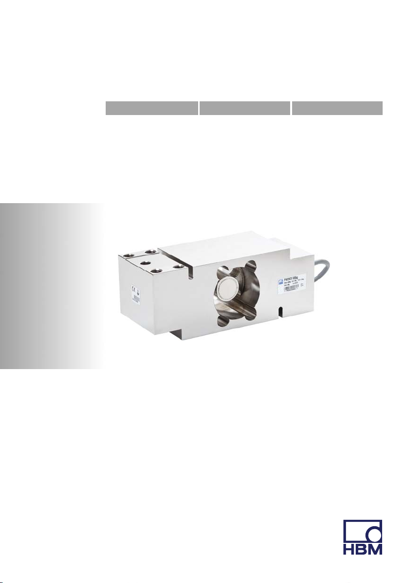
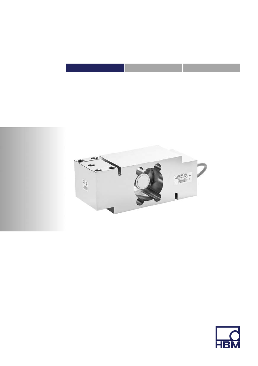
PW29…load cells are maintenance free.

Safety instructions
6A03313_02_Y00_00 HBM: public PW29
Selling on
If the load cell is sold on, these mounting instructions must be included with the
load cell.
Environmental protection, disposal
In accordance with national and local environmental protection and material
recovery and recycling regulations, old transducers that can no longer be used
must be disposed of separately and not with normal household waste.
If you need more information about waste disposal, please contact your local
authorities or the dealer from whom you purchased the product.
Qualified personnel
Qualified personnel means persons entrusted with siting, mounting, starting up
and operating the product, who possess the appropriate qualifications for their
function.
This includes people who meet at least one of the three following requirements:
1. Knowledge of the safety concepts of automation technology is a require
ment and as project personnel, you must be familiar with these concepts.
2. As automation plant operating personnel, you have been instructed how to
handle the machinery. You are familiar with the operation of the equipment
and technologies described in this documentation.
3. As commissioning engineers or service engineers, you have successfully
completed the training to qualify you to repair the automation systems. You
are also authorized to activate, ground and label circuits and equipment in
accordance with safety engineering standards.

Markings used
PW29 A03313_02_Y00_00 HBM: public 7
2 Markings used
2.1 The markings used in this document
Important instructions for your safety are specifically identified. It is essential to
follow these instructions in order to prevent accidents and damage to property.
Symbol Significance
WARNING This marking warns of a potentially dangerous
situation in which failure to comply with safety
requirements can result in death or serious physical
injury.
CAUTION This marking warns of a potentially dangerous
situation in which failure to comply with safety
requirements can result in slight or moderate physical
injury.
Notice This marking draws your attention to a situation in
which failure to comply with safety requirements can
lead to damage to property.
Important
This marking draws your attention to important
information about the product or about handling the
product.
Tip
This marking indicates application tips or other
information that is useful to you.
Information
This marking draws your attention to information
about the product or about handling the product.
Emphasis
See….
Italics are used to emphasize and highlight text and
references to other chapters and external documents.

Conditions on site
8A03313_02_Y00_00 HBM: public PW29
2.2 Symbols on the product
CE mark
The CE mark enables the manufacturer to guarantee that
the product complies with the requirements of the rele
vant EC directives (the declaration of conformity is avail
able at http://www.hbm.com/HBMdoc).
3 Conditions on site
Series PW29 load cells are hermetically encapsulated and are therefore very
insensitive to moisture influence. The transducers attain protection class IP68
(test conditions: 100 hours under 1m water column) and IP69K (water at high
pressure, steam cleaner), as per DIN EN60529. Nevertheless, the load cells
must be protected against permanent moisture influence.
3.1 Corrosion protection
The load cell must be protected against chemicals that could attack the trans
ducer body steel or the cable.
Notice
Acids and all substances that release ions also attack stainless steels and their
welded seams.
The resultant corrosion can cause the transducer to fail. If this is the case, you
must provide appropriate means of protection.
3.2 Deposits
Dust, dirt and other foreign matter must not be allowed to accumulate suffi
ciently to divert some of the measuring force onto the housing, thus invalidating
the measured value (force shunt).

Mechanical installation
PW29 A03313_02_Y00_00 HBM: public 9
4 Mechanical installation
4.1 Important precautions during installation
SHandle the transducer with care.
SWelding currents must not be allowed to flow over the transducer. If there is
a risk that this might happen, you must use a suitable low‐ohm connection
to electrically bypass the transducer. HBM, for example, provides the highly
flexible EEK ground cable, which can be screwed on above and below the
transducer.
SMake sure that the transducer cannot be overloaded.
WARNING
There is a danger of the transducer breaking if it is overloaded. This can cause
danger for the operating personnel of the system in which the transducer is
installed.
Implement appropriate safety measures to avoid overloads or to protect
against resulting dangers.
Notice
Load cells are precision measuring elements, and need to be handled carefully.
If they are dropped or knocked, the transducer may be permanently damaged.
Make sure that the transducer cannot be overloaded while it is being mounted,
either.
4.2 Mounting
Attach the load cells at the mounting holes and apply the load to the other end.
The screws and tightening torques to be used are given in the following table:

Mechanical installation
10 A03313_02_Y00_00 HBM: public PW29
Maximum capacity Thread Min. property class Tightening torque1)
100 … 250kg M8 10.9 35N⋅m
500 … 1000kg M12 10.9 110N⋅m
1) Recommendedvalue for the specified property class. Please also comply with the screw
manufacturer's instructions with regard to screw dimensions.
Set the overload stop during
installation and fix with screw
locking adhesive
Connection
cable
Direction of loading center of platform
Load application
Mounting
Spacing disc
Spacing disc
Fig. 4.1 Load application and installation
Important
Load must not be applied to the side where the cable connection is located, as
this would cause a force shunt through the cable.
Setting the overload stop
Type PW29 load cells are fitted with an adjustable overload stop. Set this over
load stop before starting up the load cell.
To do this, load the installed load cell with approx. 120% of the service load, at
the maximum eccentricity for the particular application. The maximum permiss

Mechanical installation
PW29 A03313_02_Y00_00 HBM: public 11
ible loadings stated in the specifications must not be exceeded. Note in particu
lar the “Limit load at max. 100mm eccentricity” specification, and take into con
sideration the moment produced by the eccentricity in your individual
application. Then adjust the screw of the overload stop and fix it in position with
a screw locking adhesive, such as Loctite.

Electrical connection
12 A03313_02_Y00_00 HBM: public PW29
5 Electrical connection
The following can be connected for measurement signal conditioning:
SCarrier‐frequency amplifier
SDC amplifier
designed for strain gage measurement systems.
In the standard version, the transducers come supplied with a 3m cable with a
6‐pin Pancon plug in a six‐wire configuration.
5.1 Connection with a six‐wire configuration
4
Plug‐in contact 1 (white) =
measurement signal (+)
Plug‐in contact 3 (black) =
excitation voltage (-)
Plug‐in contact 6 (gray) =
sense lead (-)
Plug‐in contact 4 (blue) =
excitation voltage (+)
Plug‐in contact 5 (green) =
sense lead (+)
Plug‐in contact 2 (red) =
measurement signal (-)
Schematic diagram of a Pancon plug (CE100F26‐6), 6‐pin
12356
blue marking
Shield (yellow) = cable shield
connected to load cell body
Fig. 5.1 Connection with a 6‐wire cable (choice of 3m or 6m lengths)
With this cable assignment, the output voltage at the amplifier is positive when
the transducer is loaded (see Fig. 4.1).
5.2 Connection with a four‐wire configuration
When transducers with a six‐wire configuration are connected to amplifiers with
a four‐wire configuration, the sense leads of the transducer must be connected
to the corresponding excitation voltage leads: (+) with (+) marking and (-) with

Electrical connection
PW29 A03313_02_Y00_00 HBM: public 13
(-) marking, see Fig. 5.1. This measure also reduces the cable resistance of
the excitation voltage leads. However, there will be a voltage loss on the supply
leads due to the cable resistance that is still present and not compensated for
by the six‐wire configuration. A large part of this loss can be eliminated by a
calibration, however, the temperature‐dependent part remains. The TKcvalue
given in the specifications for the transducer therefore does not apply for the
cable and transducer combination when connection is with a four‐wire configur
ation; the cable percentage must be added.
5.3 Shortening the cable
If the transducer is connected to an amplifier with a six‐wire configuration, the
transducer cable can be shortened as required, without adversely affecting the
measurement accuracy.
5.4 Extension cable
Only use shielded, low‐capacitance measurement cables for extension. Ensure
that connection is perfect, with a low contact resistance.
The cable of a six‐wire transducer can be extended with a cable of the same
type.
5.5 Cable protection
The transducers attain protection class IP68 as per DIN EN60529 and IP69K,
based on DIN40050 Part9 specifications. In applications where the PVC cable
of the load cell can be chemically or mechanically attacked or destroyed, extra
cable protection must be provided by means of standard cable protection sys
tems. The load cell is fitted with an adapter with an M12 internal thread, for
attaching the screwed cable gland of the flexible cable protection tubing. Fit the
cable protection system as shown in Fig. 5.2.

Electrical connection
14 A03313_02_Y00_00 HBM: public PW29
Cable protection system*, comprising
* Supplier such as Flexicon (e‐mail: info@icp‐solutions.de)
Screwed cable gland*
Flexible cable protection tubing*
O‐ring (provided by customer)
Unscrew the M12 sleeve and replace
with an M12 threaded tube coupling
Fig. 5.2 Cable protection (implemented by the customer)
5.6 EMC protection
Important
Load cells with shielded, round cables are EMC‐tested in accordance with EC
directives and are identified by CE certification. However, you must connect
the shield of the connection cable on the shielding electronics enclosure, in
order to achieve EMC protection for the measuring chain.
Electrical and magnetic fields often induce interference voltages in the measur
ing circuit. Therefore:
SUse shielded, low‐capacitance measurement cables only (HBM cables fulfill
both conditions).
SDo not route the measurement cables parallel to power lines and control
circuits. If this is not possible, protect the measurement cable with e.g.
steel conduit.

Specifications
PW29 A03313_02_Y00_00 HBM: public 15
SAvoid stray fields from transformers, motors and contact switches.
SDo not ground the transducer, amplifier and indicator more than once.
SConnect all devices in the measuring chain to the same protective earth
conductor.
6 Specifications
Information
Further product information can be found at www.hbm.com/pw.

Dimensions
16 A03313_02_Y00_00 HBM: public PW29
7 Dimensions
Connection
cable
(see section
5.5)
76
60
825 125 25
16
22
75
12
191
31
12
16
22
31
9.5
17.5
Ø14
Cable protection system
possible (see section 5.5)
Dimensions (in mm; 1 mm = 0.03937 inches)
Set the overload stop during
installation and cement with screw
locking adhesive
8 x M8 (M12 *))
*) M12 for maximum capacities 500kg to 1000kg

Mounting Instructions | Montageanleitung |
Notice de montage
English Deutsch Français
PW29

2A03313_02_Y00_00 HBM: public PW29
Deutsch
1 Sicherheitshinweise 3......................................
2 Verwendete Kennzeichnungen 7.............................
2.1 In dieser Anleitung verwendete Kennzeichnungen 7..............
2.2 Auf dem Gerät angebrachte Symbole 8.........................
3 Bedingungen am Einbauort 9...............................
3.1 Korrosionsschutz 9..........................................
3.2 Ablagerungen 9.............................................
4 Mechanischer Einbau 10.....................................
4.1 Wichtige Vorkehrungen beim Einbau 10.........................
4.2 Montage 10..................................................
5 Elektrischer Anschluss 13....................................
5.1 Anschluss in Sechsleiter‐Technik 13.............................
5.2 Anschluss in Vierleiter‐Technik 13...............................
5.3 Kabelkürzung 14..............................................
5.4 Kabelverlängerung 14.........................................
5.5 Kabelschutz 14...............................................
5.6 EMV‐Schutz 15...............................................
6 Technische Daten 17.........................................
7 Abmessungen 18............................................
Other manuals for PW29 Series
1
Table of contents
Languages:
Other HBM Accessories manuals
Popular Accessories manuals by other brands

Sandberg Active
Sandberg Active 420-72 quick guide

AGRI TRONIX
AGRI TRONIX Brecknell SBI-521 Series Service manual

Carson
Carson BA-07 Instructions for use

Sentry
Sentry W9150 Series Installation, operation & maintenance manual

Healthy Rips
Healthy Rips FURY EDGE user manual

Mophie
Mophie powerstation plus mini user manual