Omnik New Energy Omniksol-1.5k-TL User manual

User Manual -
Installation
-Operation
Omniksol-1.5k-TL
Omniksol-2k-TL
Omnik New Energy Co.,ltd

User Manual
2

User Manual
3
CATALOG
Catalog........................................................................................................................................................................................................3
1.Notes on this manual..................................................................................................................................................................5
1.1Scope of Validation..................................................................................................................................5
1.2Symbols Used...........................................................................................................................................5
1.3Target Group.............................................................................................................................................6
2.Preparation......................................................................................................................................................................................7
2.1Safety Instructions....................................................................................................................................7
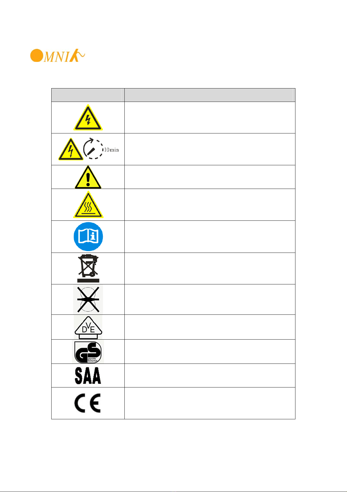
2.2Explanations of Symbols on Inverter.....................................................................................................9
3.Product Information...................................................................................................................................................................11
3.1Overview..................................................................................................................................................11
3.2Major Characteristics.............................................................................................................................12
3.3Datasheet.................................................................................................................................................13
4.Packing checklist........................................................................................................................................................................15
4.1Assembly parts........................................................................................................................................15
4.2Product Appearance..............................................................................................................................16
4.3Product Identification..............................................................................................................................17
4.4Further Information.................................................................................................................................17
5.Installation......................................................................................................................................................................................18
5.1Safety.......................................................................................................................................................18
5.2Mounting Instructions.............................................................................................................................18
5.3Safety Clearance....................................................................................................................................19
5.4Mounting Procedure...............................................................................................................................20
5.5Safety lock...............................................................................................................................................21
6.Electrical Connection................................................................................................................................................................23
6.1Safety.......................................................................................................................................................23
6.2Overview of Connection Area...............................................................................................................23
6.3AC Side Connection...............................................................................................................................24
6.4DC Side Connection...............................................................................................................................26
6.5DC Side Disconnection..........................................................................................................................29

User Manual
4
6.6Communication and Monitoring Device..............................................................................................29
7.Display.............................................................................................................................................................................................31
7.1LCD Panel...............................................................................................................................................31
7.2LCD Display.............................................................................................................................................32
7.3Set Language..........................................................................................................................................34
7.4State Information....................................................................................................................................35
8.Recycling and Disposal...........................................................................................................................................................36
9.Troubleshooting...........................................................................................................................................................................37
10.Abbreviation..............................................................................................................................................................................38
11.Contact........................................................................................................................................................................................39

User Manual
5
1. NOTES ON THIS MANUAL
1.1 Scope of Validation
The main purpose of this User’s Manual is to provide instructions and detailed
procedures for installing, operating, maintaining, and troubleshooting the following two
types of Omnik New Energy-Solar Inverters:
•Omniksol-1.5k-TL
•Omniksol-2k-TL
Please keep this user manual all time available in case of emergency.
1.2 Symbols Used
DANGER
DANGER indicates a hazardous situation which, if not
avoided, will result in death or serious injury.
WARNING
WARNING indicates a hazardous situation which, if not
avoided, can result in death or serious injury or moderate
injury
CAUTION
CAUTION indicates a hazardous condition which, if not
avoided, can result in minor or moderate injury.
NOTICE
NOTICE indicates a situation that can result in property
damage, if not avoided.

User Manual
6
1.3 Target Group
•Chapter 1, 2, 3, 4, 7, 8, 9, 10 and Chapter 11 are intended for anyone who is
intended to use Omnik Grid Tie Solar Inverter. Before any further action, the operators must
first read all safety regulations and be aware of the potential danger to operate high-voltage
devices. Operators must also have a complete understanding of this device’s features and
functions.
•Chapter 5 and Chapter 6 are only for qualified personnel who are intended to install
or uninstall the Omnik Grid Tie Solar Inverter.
WARNING
Do not use this product unless it has been successfully installed
by qualified personnel in accordance with the instructions in
Cha
p
ter 5
,
“Installation”.
NOTICE
Hereby qualified personnel means he/she has the valid license
from the local authority in:
•Installing electrical equipment and PV power systems
(up to 1000 V).
•Applying all applicable installation codes.
•Analyzing and reducing the hazards involved in
performing electrical work.
•Selecting and using Personal Protective Equipment
(
PPE
)
.

User Manual
7
2. PREPARATION
2.1 Safety Instructions
DANGER
DANGER due to electrical shock and high voltage
DO NOT touch the operating component of the inverter, it
might result in burning or death.
TO prevent risk of electric shock during installation and
maintenance, please make sure that all AC and DC terminals
are plugged out.
DO NOT stay close to the instruments while there is severe
weather conditions including storm, lighting etc.
WARNING
The installation,service ,recycling and disposal of the
inverters must be performed by qualified personnel only in
compliance with national and local standards and
regulations. Please contact your dealer to get the
information of authorized repair facility for any maintenance
or repairmen.
Any unauthorized actions including modification of product
functionality of any form will affect the validation of warranty
service; Omnik may deny the obligation of warranty service
accordin
g
l
y
.
NOTICE
Public utility only
The PV inverter designed to feed AC power directly into the
public utility power grid,do not connect AC output of the
device to any private AC equipment.

User Manual
8
CAUTION
The PV inverter will become hot during operation; please
don’t touch the heat sink or peripheral surface during or
shortly after operation。
Risk of damage due to improper modifications.
Never modify or manipulate the inverter or other components
of the system.

User Manual
9
2.2 Explanations of Symbols on Inverter
Symbol Description
Dangerous electrical voltage
This device is directly connected to public grid, thus all
work to the inverter shall only be carried out by
qualified personnel.
DANGER to life due to high electrical voltage!
There might be residual currents in inverter because
of large capacitors. Wait 10 MINUTES before you
remove the front lid.
NOTICE, danger!
This device directly connected with electricity
generators and public grid.
Danger of hot surface
The components inside the inverter will release a log
of heat during operation, DO NOT touch aluminum
housing during operating.
An error has occurred
Please go to Chapter 10 “Trouble Shooting” to remedy the
error.
This device SHALL NOT be disposed of in
residential waste
Please go to Chapter 9 “Recycling and Disposal” for
proper treatments.
Without Transformer
This inverter does not use transformer for the isolation
function.
German mark of conformity
The inverter complies with the requirement of the
German Grid Regulations.
Certified Safety
The inverter complies with the requirements of the
Equipment and Product Safety Act in Europe.
Standards Association of Australian
The inverter complies with the requirement of the
AS4777.
CE Mark
Equipment with the CE mark fulfils the basic
requirements of the Guideline Governing Low-Voltage
and Electromagnetic Compatibility.

User Manual
10
No unauthorized perforations or modifications
Any unauthorized perforations or modifications are
strictly forbidden, if any defect or damage
(device/person) is occurred, Omnik shall not take any
responsibility for it.

User Manual
11
3.PRODUCT INFORMATION
3.1 Overview
•Industrial Layout
、
•Excellent Heat Elimination

User Manual
12
•Effective Shield For DC/AC/Communication Connections
3.2 Major Characteristics
Omnik inverter has following characteristics which make Omnik inverter “High Efficiency,
High Reliability, High Cost Effective Ratio”
•Wide DC input voltage and current ranges, enables more PV panels connected.
•Wide MPP voltage range ensure high yield under various weather conditions.
•High MPP tracking accuracy, ensure the minimum power loses during converting.
•Complete set of protection methods.
Also, following protection methods are integrated in Omnik inverter:
•Internal overvoltage
•DC insulation monitoring
•Ground fault protection
•Grid monitoring
•Ground fault current monitoring
•DC current monitoring
•Integrated DC switch (Optional)

User Manual
13
3.3 Datasheet
Type Omniksol-1.5k-TL Omniksol-2k-TL
Input (DC)
Max. PV-generator power Ppv [W] 1750 2300
Max DC voltage Vmax(DC) [V] 500
MPPT DC voltage range Vmppt [V] 120 - 450
Turn off DC Voltage Vmin(DC) [V] 120
Max. DC current Imax(DC) [A] 18
Nominal DC current IN(DC) [A] 14 16.5
Number of DC connection 1
DC-connection Amphenol H4
Number of MPP trackers 1
Turn on power Pmin(DC) [W] 10
Output (AC)
Max. AC Power Pmax(AC) [V] 1650 2200
Nominal AC power PN(AC) [W] 1500 2000
Max. AC current Imax(AC) [A] 9.0 12.0
Nominal AC current IN(AC) [A] 6.5 8.5
Power connection Single phase Single phase
Grid voltage range According to VDE 0126-1-1, RD1663, ENEL2010,C10/11,
G83/1 AS4777
Grid frequency range According to VDE 0126-1-1, RD1663, ENEL2010,C10/11,
G83/1, AS4777
Power factor 0.99 (>30% of Full Load)
Harmonic distortion (THD) at nominal output <2%
AC Connector Plug-in connector
Power consumption
Own consumption in operation Pown(AC) [W] 30
Power consumption at night Pnig(AC) [W] 0
Power consumption at standby Pstd(AC) [W] 6
Efficiency
Max. Efficiency (at 360VDC) 97.4%
Euro efficiency (at 360VDC) 96.6%
MPPT efficiency 99.9%
Safety and protection
Internal overvoltage protection Yes
DC Insulation monitoring Yes
Earth fault protection Yes
Grid monitoring According to VDE 0126-1-1, RD1663, ENEL2010,C10/11
G83/1, AS4777
Earth fault current monitoring According to VDE 0126-1-1, RD1663, ENEL2010,C10/11
G83/1, AS4777
DC current monitoring According to VDE 0126-1-1, RD1663, ENEL2010,C10/11
G83/1, AS4777
Islanding protection According to VDE 0126-1-1, RD1663, G83/1, AS4777
Normative reference
CE- compliant according to EN 62109, EN 61000-6-1, EN 61000-6-3, EN 61000-6-2, EN
61000-6-4
EN61000-3-2, EN61000-3-3, EN61000-3-12, EN61000-3-11
Dimensions and weight
Dimensions (WxHxD) [mm] 330x425x130

User Manual
14
Weight [kg] 13
Environmental limits
IP protection type IP 65 according to IEC 60529
Operating temperature range -20°C to +60°C
Relative humidity 0% to 98%, no condensation
Maximum altitude (above sea level) [m] 2000
Noise level [dBA] < 40
General data
Isolation type Transformerless
Cooling concept Convection
Housing Metal housing for inside and outside installation
Mounting information Wall bracket
LED display 3
LCD display Backlight, 16 x 2 Character LCD
Data logger RS485, Optional (Wi-Fi, GPRS, Ethernet)
Data communication interfaces
Computer Communication RS232 as Option
Standard warranty 5 years (optional 10 years)

User Manual
15
4.PACKING CHECKLIST
4.1 Assembly parts
After you receive the Omnik inverter, please check if there is any damage on the carton,
and then check the inside completeness for any visible external damage on the inverter
or any accessories. Contact your dealer if anything is damaged or missing.
A B C D
E F G H
Object Quantity Description
A 1 Omnik inverter
B 1 pair DC connector
C 1 AC connector
D 1 Ring tool to disconnect DC connector
E 4 Screw (ST6×50)
F 4 Expansion tube
G 1 Installation and operating instructions
H 1 DC Switch (Optional)

User Manual
16
4.2 Product Appearance
•Front
Object Description
A Removable front shield
B LED light(Green) – RUN
C LED light(Red) – FAULT
D LED light(Yellow) – COM
E Function key for displays and choice of language
F Monitoring LCD with backlighting
•Bottom
A
A
F
F
E
E
D
D
C
C
B
B
A B C

User Manual
17
Object Description
A Plug connectors for DC input.
B RS232/RS485 interface
C Terminal for grid connection (AC output)
4.3 Product Identification
You can identify the inverter by the side nameplate. Information such as serial number
(SN.), type of the inverter, as well as inverter specifications are specified on the side
name plate. The name plate is on the middle part of the right side of the inverter housing.
And the following figure is the side name plate example as on Omniksol-1.5k-TL.
4.4 Further Information
If you have any further questions concerning the type of accessories or installation,
please check our website www.omnik-solar.com or contact our service hotline.

User Manual
18
5. INSTALLATION
5.1 Safety
5.2 Mounting Instructions
DANGER
DANGER to life due to potential fire or electricity shock.
DO NOT install the inverter near any inflammable or
explosive items.
This inverter will be directly connected with HIGH
VOLTAGE power generation device, the installation must
be performed by qualified personnel only in compliance with
national and local standards and regulations.
NOTICE
NOTICE due to the inappropriate or the harmonized
installation environment may jeopardize the life span
of the inverter.
Installation directly expose under intensive sunshine is not
recommended.
The installation site MUST have good ventilation condition.
M
Ma
ax
x
1
15
5°
°

User Manual
19
•Omnik inverter is designed for indoors and outdoors installation
•Please mount the inverter in the direction as illustrated above
•Install the inverter in the vertical direction is recommended, with a max.15 degrees
backwards.
•For the convenience of checking the LCD display and possible maintenance
activities, please install the inverter at eye level.
•Make sure the wall you selected is strong enough to handle the screws and bear the
weight of the inverter
•Ensure the device is properly fixed to the wall
•It is not recommended that the inverter is exposed to the strong sunshine, because
the excess heating might lead to power reduction
•The ambient temperature of installation site should be between -20 °C and +60 °C
( between -4 °F and 140 °F )
•Make sure the ventilation of the installation spot, not sufficient ventilation may reduce
the performance of the electronic components inside the inverter and shorten the life
of the inverter
5.3 Safety Clearance
Observe the following minimum clearances to walls, other devices or objects to
guarantee sufficient heat dissipation and enough space for pulling the electronic solar
switch handle.
10 CM
10 CM
30 CM
30 CM

User Manual
20
Direction Minimum clearance
Above 30 cm
Below 30 cm
Sides 10 cm
5.4 Mounting Procedure
1. Mark 4 positions of the drill holes on the wall according to the paper installation
position scale packed in the carton box.
2. First, according to the marks, drill 4 holes in the wall. Then, place four expansion
tubes in the holes using a rubber hammer. Next, wring 4 screws into the expansion
tubes.
4
4
-
-
Φ
Φ
1
1
2
2
2
2
5
5
4
4
±
±
1
1
3
32
20
0
±
±
2
2
This manual suits for next models
1
Table of contents
Other Omnik New Energy Inverter manuals

Omnik New Energy
Omnik New Energy Omniksol-5k-TL2-3P User manual

Omnik New Energy
Omnik New Energy Omniksol-5k-TL2-TH User manual

Omnik New Energy
Omnik New Energy Omniksol-3k-TL User manual

Omnik New Energy
Omnik New Energy Omniksol-1k-TL2 User manual

Omnik New Energy
Omnik New Energy Omniksol-4k-TL2-TH User manual

Omnik New Energy
Omnik New Energy Omniksol-3k-TL2 User manual