Metabo E 140 SP Plus User manual

115 168 8825 / 2409 - 3.4
E 130
E 140 SP
E 140 SP Plus
E 150
E 170 Si
Original Betriebsanleitung . . . . . . . . . . . . . .3
Original operating instructions . . . . . . . . . . .7
Instructions d’utilisation originales . . . . . . .11
Origineel gebruikaanwijzing. . . . . . . . . . . .15
Manuale d’uso originale. . . . . . . . . . . . . . .19
Manual de instrucciones original . . . . . . . .23
Original brugsvejledning . . . . . . . . . . . . . .27
Original instruksjonsbok. . . . . . . . . . . . . . .31
Original bruksanvisning . . . . . . . . . . . . . . .35
S0033_34IVZ.fm

2
U2S0033.fm

3
DEUTSCH
1. Zuerst lesen! ...............................3
2. Sicherheitshinweise ...................3
2.1 Bestimmungsgemäße
Verwendung..................................3
2.2 Allgemeine Sicherheitshinweise ...3
2.3 Symbole auf dem Gerät................4
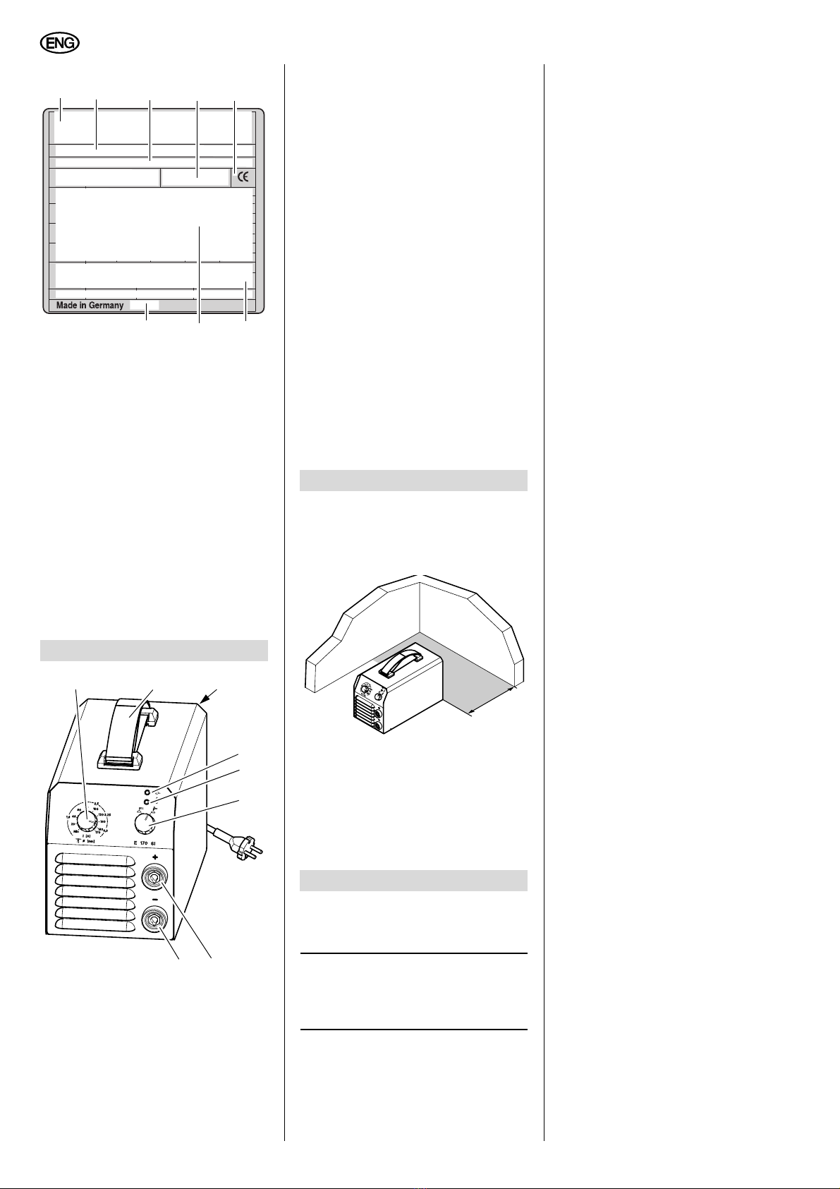
3. Bedienelemente ..........................4
4. Betriebsvorbereitung .................4
4.1 Aufstellen ......................................4
5. Bedienung ...................................4
5.1 Elektrodenschweißen ...................4
5.2 WIG-Schweißen............................4
5.3 Betrieb beenden ...........................5
6. Wartung .......................................5
7. Lieferbares Zubehör .............. 5/39
8. Reparatur.....................................5
9. Umweltschutz..............................5
10. Störungen....................................5
11. Störungsbehebung.....................5
12. Technische Daten .......................6
Diese Betriebsanleitung wurde so
erstellt, dass Sie schnell und sicher mit
Ihrem Gerät arbeiten können. Hier ein
kleiner Wegweiser, wie Sie diese
Betriebsanleitung lesen sollten:
−Lesen Sie diese Betriebsanleitung
vor der Inbetriebnahme ganz durch.
Beachten Sie insbesondere die
Sicherheitshinweise.
−Diese Betriebsanleitung richtet sich
an ausgebildete Lichtbogenschwei-
ßer oder Fachkräfte mit ähnlicher
Qualifikation.
−Bewahren Sie alle mit diesem Gerät
gelieferten Unterlagen auf, damit
Sie sich bei Bedarf informieren kön-
nen. Bewahren Sie den Kaufbeleg
für eventuelle Garantiefälle auf.
−Wenn Sie das Gerät einmal verlei-
hen oder verkaufen, geben Sie alle
mitgelieferten Geräteunterlagen mit.
−Für Schäden, die entstehen, weil
diese Betriebsanleitung nicht beach-
tet wurde, übernimmt der Hersteller
keine Haftung.
Die Informationen in dieser Betriebsan-
leitung sind wie folgt gekennzeichnet:
Gefahr!
Warnung vor Personen-
schäden oder Umwelt-
schäden.
Stromschlaggefahr!
Warnung vor Personen-
schäden durch Elektrizi-
tät.
Achtung!
Warnung vor Sach-
schäden.
Hinweis:
Ergänzende Informationen.
−Zahlen in Abbildungen (1, 2, 3, ...)
−kennzeichnen Einzelteile;
−sind fortlaufend durchnumme-
riert;
−beziehen sich auf entspre-
chende Zahlen in Klammern (1),
(2), (3) ... im benachbarten Text.
−Handlungsanweisungen, bei denen
die Reihenfolge beachtet werden
muss, sind durchnummeriert.
−Handlungsanweisungen mit belie-
biger Reihenfolge sind mit einem
Punkt gekennzeichnet.
−Auflistungen sind mit einem Strich
gekennzeichnet.
2.1 Bestimmungsgemäße
Verwendung
Das Schweißgerät ist bestimmt für das
Verschweißen aller Metalle.
Das Schweißgerät und die dazugehörige
Schweißplatzausrüstung entsprechen
bei Auslieferung den einschlägigen
Bestimmungen (EMC-Klassifizierung
nach CISPR 11: Klasse A).
Das Schweißgerät ist bestimmt für den
Gebrauch durch ausgebildete Lichtbo-
genschweißer oder Fachkräfte mit ähn-
licher Qualifikation.
Zugelassene Schweißverfahren:
−Elektrodenschweißen
−WIG DC (mit optionalem Zubehör)
für alle Metalle mit Ausnahme von
Aluminium.
Geräteleistungen siehe „Technische
Daten“.
Jede andere Verwendung gilt als
bestimmungswidrig und ist verboten.
Durch bestimmungswidrige Verwen-
dung, Veränderungen am Gerät oder
durch den Gebrauch von Teilen, die
nicht vom Hersteller geprüft und freige-
geben sind, können unvorhersehbare
Schäden entstehen!
2.2 Allgemeine Sicherheits-
hinweise
•Beachten Sie beim Gebrauch
dieses Gerätes die folgenden
Sicherheitshinweise, um Gefahren
für Personen oder Sachschäden
auszuschließen.
•Beachten Sie die speziellen Sicher-
heitshinweise in den jeweiligen
Kapiteln.
•Beachten Sie die gesetzlichen
Richtlinien oder Unfallverhütungs-
Vorschriften für den Umgang mit
Lichtbogenschweißgeräten.
BGefahr!
Elektrische Spannung.
•Schließen Sie das Gerät nur an eine
Stromquelle an, deren Schutzein-
richtungen einwandfrei funktionie-
ren.
Wenden Sie sich im Zweifelsfall an
eine Elektrofachkraft!
•Reparaturen und Eingriffe in die
Geräte dürfen nur von ausgebil-
deten Elektrofachkräften durchge-
führt werden.
•Vor Öffnen des Gerätes müssen Sie
die Netzverbindung trennen.
A
Gefahr!
•Tragen Sie bei Schweißarbeiten
unbedingt ausreichende Schutz-
kleidung.
•Verwenden Sie unbedingt Schutz-
schild und Schutzhandschuhe.
Sie schützen sich dadurch vor Fun-
kenflug und Lichtbogenstrahlung.
•Alle Metalldämpfe sind schädlich!
Sorgen Sie bei Arbeiten in geschlos-
senen Räumen immer für eine
ausreichende Belüftung und Absau-
gung, damit die maximalen Schad-
stoffkonzentrationen am Arbeits-
platz nicht überschritten werden.
Die Dämpfe von Blei, Cadmium,
Kupfer, Chrom, Nickel, Zink und
Beryllium sind besonders gefährlich!
A
Achtung!
•Schweißen Sie niemals ein
Schweißgut, das geerdet ist.
Sie vermeiden so eine eventuelle
Beschädigung der Schutzleiter
durch vagabundierende Schweiß-
ströme (Potentialverschleifungen).
•Benutzen Sie das Schweißgerät nie-
mals zum Auftauen von Rohren.
•Befestigen Sie die Klemme der
Schweißstromrückleitung immer
direkt am Schweißgut und so nah
wie möglich an der Schweißstelle.
•Tragen Sie das Schweißgerät
immer am Tragegurt, wenn Sie es
transportieren.
•Besondere Vorsicht ist geboten,
wenn Sie mit dem Gerät in der Nähe
von Computern, elektronisch
gesteuerten Anlagen oder in der
Nähe von magnetischen Datenträ-
gern (Tonbänder, Disketten, Daten-
bändern, Scheckkarten o.ä.) arbei-
ten.
Inhaltsverzeichnis
1. Zuerst lesen!
2. Sicherheitshinweise
XS0015D3.fm Original Betriebsanleitung DEUTSCH

4
DEUTSCH
Bei der Lichtbogenzündung kann es
zu Fehlfunktionen der Anlagen oder
Datenverlusten kommen.
2.3 Symbole auf dem Gerät
Lichtbogenschweißen mit
umhüllter Stabelektrode
Wolfram-Inertgas-Schwei-
ßen (WIG-Schweißen)
(Gilt nicht für E 140 SP/
Plus)
Angaben auf dem Leistungsschild:
4.1 Aufstellen
AAchtung!
Stellen Sie das Gerät immer
nur auf den Gerätefüßen ab.
Das Gerät saugt an der Frontseite
und am Boden Luft an und gibt sie an
der Rückseite durch die Lüftungs-
schlitze wieder ab. Achten Sie unbe-
dingt auf einen ungehinderten Luft-
strom. Der Abstand des Geräts von
Wänden oder anderen Geräten muss
mindestens 20 cm betragen.
AAchtung!
Überprüfen Sie vor dem Ein-
schalten des Gerätes sämtliche
Anschlüsse und Zuleitungen.
3Hinweis:
Das Gerät verwendet beim Elek-
trodenschweißen die Hot-Start-, Arc-
Force- und Anti-Stick-Funktion.
Hot-Start-Funktion
Bei Berührung des Werkstücks mit der
Elektrode wird der eingestellte Schweiß-
strom für kurze Zeit erhöht, um ein
sicheres Zünden des Lichtbogens zu
erreichen.
Die kurzfristige Erhöhung des Schweiß-
stroms ist auf den maximalen Elektro-
denstrom begrenzt.
Arc-Force-Funktion
Während des Schweißprozesses hält
das Gerät die Energie (Wärme) kons-
tant, die in das Material eingebracht
wird, auch wenn sich der Abstand der
Elektrode zum Schweißbad ändert.
Anti-Stick-Funktion
Erkennt das Gerät einen Kurzschluss im
Schweißprozess, wird nach 0,5 Sekun-
den auf Minimalstrom geschaltet, um ein
Ausglühen der Elektrode zu verhindern
5.1 Elektrodenschweißen
1. Schweißstromrückleitung am
- Pol anschließen.
2. Schweißleitung am + Pol anschlie-
ßen.
AAchtung!
Beachten Sie die Verpackungs-
hinweise zur Polung der Elektroden,
die Sie verwenden und polen Sie
gegebenenfalls die Anschlüsse um.
AAchtung!
Die Lift-Arc-Zündung muss
beim Elektrodenschweißen ausge-
schaltet sein (Gilt nicht für E 140 SP/
Plus). Zur Kontrolle den Drehschalter
gegen den Uhrzeigersinn drehen.
3. Schweißstromrückleitung an geeig-
neter Stelle am Werkstück befesti-
gen.
4. Hauptschalter einschalten.
5. Gewünschten Schweißstrom ein-
stellen.
Das Schweißgerät ist jetzt betriebs-
bereit.
5.2 WIG-Schweißen
Bei Verwendung eines WIG-Schweiß-
brenners (optionales Zubehör) können
die Geräte auch für das WIG-Schweißen
eingesetzt werden.
1. Schweißstromkabel des WIG-
Schweißbrenners anschließen
(- Pol).
2. Gasversorgung des WIG-Brenners
prüfen.
3. Schweißstromrückleitung an geeig-
neter Stelle am Werkstück befesti-
gen (+ Pol).
4. Hauptschalter einschalten.
1Hersteller
2Gerätebezeichnung
3Seriennummer
4Normenhinweis – Diese Gerät
erfüllt die Anforderungen der
genannten Norm
5CE-Zeichen – Dieses Gerät
erfüllt die EU-Richtlinien gemäß
Konformitätserklärung
6Entsorgungssymbol – Gerät
kann über Hersteller entsorgt
werden
7Elektrische Leistungsdaten
8Baujahr
3. Bedienelemente
9Schweißstromeinstellung
2345
78
1
6
911
10
12
13
14
15
16
10 E 130, E 150, E 170 Si:
Trage-/Schultergurt
In der Länge verstellbar zum
Transport
−an der Hand (wie in der
Abb. dargestellt)
−über die Schulter.
E 140 SP/Plus: Tragegriff
11 Hauptschalter
schaltet das Gerät ein oder aus
12 Betriebsanzeige
13 Störungsanzeige
LED blinkt:
−bei Unterspannung
−bei Überspannung
−bei zu hoher Betriebs-
temperatur.
14 Umschalter Elektrode –
WIG DC (Lift-Arc-Zündung)
(Gilt nicht für E 140 SP/Plus)
15 Anschluss Schweißstrom + Pol
16 Anschluss Schweißstrom - Pol.
LED = Licht-Emittierende Diode,
dient als Kontrolleuchte.
4. Betriebsvorbereitung
5. Bedienung
>20 cm

5
DEUTSCH
5. Gewünschten Schweißstrom ein-
stellen.
6. Lift-Arc-Zündung einschalten
(Gilt nicht für E 140 SP/Plus).
Zur Kontrolle den Drehschalter im
Uhrzeigersinn drehen.
Das Schweißgerät ist jetzt betriebsbe-
reit.
WIG-Schweißen
Die Zündung des Lichtbogens erfolgt
ausschließlich durch Berühren des
Werkstücks mit der Elektrode (Lift-Arc-
Zündung).
Die Elektrode wird an das Werkstück
angenähert.
Durch den Kontakt der Elektrode mit
dem Werkstück entsteht ein Kurz-
schluss. Der Schweißstrom wird redu-
ziert. Das Material wird erwärmt und ein
Kurzschlusslichtbogen erzeugt.
Durch Abziehen der Elektrode zündet
der Lichtbogen und es fließt der einge-
stellte Schweißstrom (Gilt nicht für
E 140 SP/Plus).
5.3 Betrieb beenden
1. Hauptschalter auf „0“ stellen.
2. Verbindung der Schweißstromrück-
leitung zum Werkstück trennen.
3. Netzstecker ziehen.
Das Schweißgerät ist weitgehend war-
tungsfrei.
Je nach Staubbelastung sollte es alle 4
bis 6 Monate mit trockener und ölfreier
Druckluft ausgeblasen werden.
Überprüfen Sie in regelmäßigen Abstän-
den das Gerät auf sichtbare Mängel.
Benachrichtigen Sie bei Schäden an den
Kabeln eine Elektrofachkraft.
Für besondere Aufgaben erhalten Sie im
Fachhandel folgendes Zubehör – die
Abbildungen finden Sie auf der hinteren
Umschlagseite.
Dieses Zubehör ist mit dem Gerät getes-
tet worden und garantiert ein problem-
loses Arbeiten.
AWIG-Schweißbrenner
SR 17 V für E 130/E 150,
E 140 SP/Plus
wird benötigt für WIG-Schweißen.
1) mit 2 m Anschlusslänge
2) mit 4 m Anschlusslänge
3) mit 8 m Anschlusslänge
BWIG-Schweißbrenner
SR 26 V für E 170 Si,
wird benötigt für WIG-Schweißen.
1) mit 4 m Anschlusslänge
2) mit 8 m Anschlusslänge
CDruckminderer mit 2 Manometern
1) ohne Absperrventil
2) mit Absperrventil
DSchweißschild
1) als Kopfhaube
2) Automatik-Schutzschirm
AGefahr!
Reparaturen an Elektrowerk-
zeugen dürfen nur durch eine Elektro-
fachkraft ausgeführt werden!
Reparaturbedürftige Schweißgeräte
können an die Service-Niederlassung
Ihres Landes eingesandt werden. Die
Adresse finden Sie bei der Ersatzteil-
liste.
Bitte beschreiben Sie bei der Einsen-
dung zur Reparatur den festgestellten
Fehler.
Das Verpackungsmaterial der Maschine
ist zu 100 % recyclingfähig.
Ausgediente Elektrowerkzeuge und
Zubehör enthalten große Mengen wert-
voller Roh- und Kunststoffe, die eben-
falls einem Recyclingprozess zugeführt
werden können.
Die Anleitung wurde auf chlorfrei
gebleichtem Papier gedruckt.
Das Schweißgerät ist mit einer Überlast-
sicherung ausgestattet. Bei zu hoher
Betriebstemperatur, Unter- oder Über-
spannung schaltet sich das Gerät auto-
matisch ab.
−Die Anzeige „Störung“ blinkt.
Bei zu hoher Betriebstemperatur:
−Lassen Sie das Gerät eingeschaltet.
So kann der Lüfter das Gerät
schneller abkühlen.
−Die Anzeige „Störung“ erlischt,
wenn die Temperatur auf normale
Werte abgesunken ist.
Sie können jetzt weiterarbeiten.
Bei Unter- oder Überspannung:
−Prüfen Sie die Netzspannung.
6. Wartung
7. Lieferbares Zubehör
8. Reparatur
9. Umweltschutz
10. Störungen
11. Störungsbehebung
Spröde oder poröse Schweißnaht
Unsauberes
Werkstück?
Rost, Fett oder
andere Verunrei-
nigungen vor
dem Schweißen
entfernen.
Kein Schweißstrom
Schweißstrom-
rückleitung gibt
keinen richtigen
Kontakt?
Schweißstrom-
rückleitung auf
richtigen Kon-
takt prüfen.
Anzeige "Stö-
rung" blinkt
Netzspannung
und Lüfter prüfen
Elektronik
defekt?
Service
informieren
Keine Funktion des Gerätes
Netzsicherung
ausgelöst?
Netzsicherung
einschalten oder
wechseln.

6
DEUTSCH
12. Technische Daten
Gerät E 130*E 140 SP*E 140 SP Plus*E 150*E 170 Si
Netzanschluss: 230 V (-15% / -20%) / 50 – 60 Hz
Leerlaufspannung Elektrode: V90 103 85 90 90
Leerlaufspannung WIG: V25 –85 25 25
Arbeitsspannung Elektrode: V20,4 – 25,2 20,4 – 25,6 20,4 – 26 20,4 – 26 20,4 – 26,8
Arbeitsspannung WIG: V10,4 – 15,2 –10,4 – 15,6 10,4 – 16 10,4 – 16,8
Stromeinstellbereich, stufenlos: A10 – 130 10 – 140 10 – 140 10 – 150 10 – 170
Eingangsleistung max.: kVA 6,0 6,6 6,6 7,1 5,7
Eingangshöchststrom: A26 29 29 31 25
Max. Einschaltdauer E 40 °C: %25 15 20 25 25
Max. Einschaltdauer WIG 40 °C: %35 –25 35 35
60% Einschaltdauer E 40 °C: A100 85 85 110 130
60% Einschaltdauer WIG 40 °C: A115 –100 130 140
100% Einschaltdauer E 40 °C: A80 75 75 90 100
100% Einschaltdauer WIG 40 °C: A100 –85 110 110
Schutzart: IP23C IP23C IP23C IP23C IP23C
Verschweißbare Elektroden: Ø mm 3,25 3,25 3,25 3,25 (4,0 CrNi) 4,0
Kühlart: F F F F F
Netzsicherung: T16A T16A T16A T16A T16A
Maße L x B x H (mm): mm 300x130x210 300x130x210 300x130x210 300x130x210 400x210x240
Gewicht (netto): kg 6,2 5,8 6,0 6,3 7,8
* Achtung: Dieses Gerät erfüllt nicht die Anforderungen der EN/IEC 61000 3-12. Wenn das Gerät an ein öffentliches Versorgungs-
netzt angeschlossen werden soll, liegt es, ggf. nach Konsultation mit dem Betreiber des Versorgungsnetzes, in der Verantwortung
des Betreibers oder des Anwenders des Gerätes sicherzustellen, dass das Gerät angeschlossen werden kann.

7
ENGLISH
1. Please Read First!.......................7
2. Safety Information ......................7
2.1 Specified conditions of use ...........7
2.2 General safety information............7
2.3 Symbols on the machine ..............7
3. Operating Elements....................8
4. Preparing for Operation .............8
4.1 Placing the machine .....................8
5. Operation.....................................8
5.1 Manual arc welding.......................8
5.2 TIG welding...................................8
5.3 Shutting down ...............................9
6. Maintenance ................................9
7. Available Accessories...........9/39
8. Repairs.........................................9
9. Environmental Protection ..........9
10. Disorders .....................................9
11. Trouble Shooting ........................9
12. Technical Specifications..........10
These instructions are written in a way
that will enable you to safely use the
machine in a minimum of time. Here is
how to read the instructions:
−Read these instructions completely
before use. Pay special attention to
the safety information.
−These instructions are intended for
skilled arc weldors or other special-
ists of similar qualification.
−Keep all documents supplied with
the machine for future reference.
Retain proof of purchase for possi-
ble warranty claims.
−If you hire out or sell this machine be
sure to hand over all documents
supplied with the machine.
−The equipment manufacturer is not
liable for any damage arising from
disregard of these instructions.
The information in these instructions is
marked as under:
Danger!
Warning of personal
injury or environmental
damage.
Risk of electric shock!
Risk of personal injury
by electric shock.
Caution!
Risk of material damage
Note:
Supplementary informa-
tion.
−Numbers in illustrations (1, 2, 3, ...)
−indicate component parts;
−are consecutively numbered;
−refer to the corresponding num-
bers in brackets (1), (2), (3) ... in
the neighbouring text.
−Instructions to be carried out in
sequence are numbered.
−Instructions which can be carried
out in any sequence are preceded
by a bullet (•).
−Listing are preceded by a M-dash (–).
2.1 Specified conditions of
use
This welding machine is intended for
welding all metals.
The welding machine and the accessory
kit supplied conform to the relevant regu-
lations applicable at the time of delivery.
This welding machine is intended for
operation by professional arc weldors or
specialists of similar qualification.
Permissible welding processes:
−Manual arc welding
−TIG DC (with optional accessories)
for all metals, except aluminium.
For machine performance see “Techni-
cal Specifications”.
Any other use is not as specified and
prohibited.
Unspecified use, modification of the
machine or use of parts not tested and
approved by the equipment manufac-
turer could cause unforeseeable dam-
age!
2.2 General safety informa-
tion
• When using this machine, observe
the following safety instructions to
exclude the risk of personal injury or
material damage.
• Follow the specific safety instruc-
tions in the respective chapters.
• Follow the legal directives or regula-
tions for the prevention of accidents
pertaining to the handling of arc
welding machines.
BDanger!
Electric potential!
• Connect the machine only to a prop-
erly earthed outlet.
If in doubt check with a qualified
electrician!
• Service and repairs to the machine
must only be made by qualified elec-
tricians.
• Unplug before removing the
machine's cover.
A
Danger!
• Wear sufficient protective clothing
when welding.
• Always use a welding visor and
welder's gloves.
They provide protection against fly-
ing sparks and arc radiation.
• All metal fumes are detrimental to
health!
When working indoors ensure suffi-
cient ventilation and extraction in
order to not exceed the max. per-
missible workplace pollutant con-
centration.
The fumes of lead, cadmium, cop-
per, chromium, nickel, zinc and
beryllium are particularly harmful!
A
Caution!
• Never weld earthed metal.
Welding earthed metal may cause
damage to the protective earth con-
ductors by stray currents.
• Never use the welding machine for
thawing pipes.
• Always attach the earth cable
directly to the weld metal and as
close as possible to the welding
spot.
• Always carry the welding machine at
the carrying strap when transport-
ing it.
• Special care is required when work-
ing near computers, electronically
controlled equipment or in the prox-
imity of magnetic data media (sound
recording tapes, floppy disks, data
recording tapes, credit cards, etc.).
The arc start can cause misfunction
of this type of equipment or data
loss.
2.3 Symbols on the machine
Arc welding with coated
stick electrodes
Tungsten Inert-gas Welding
(TIG welding)
(not applicable for
E 140 SP/Plus)
Table of Contents
1. Please Read First!
2. Safety Information
XS0015E3.fm Original operating instructions DEUTSCH

8
ENGLISH
Information on the name plate:
4.1 Placing the machine
ACaution!
Always stand the machine on
its feet only.
The machine draws in air at its front
and bottom, which is given off
through the ventilating slots at the
rear. Ensure an unhindered airflow.
The distance of the machine to walls
or other equipment must be at least
20 cm.
ACaution!
Check all connections and
supply lines before turning on.
3Note:
For manual arc welding this
machine uses the Hot-start, Arc-force
and Anti-stick functions.
Hot-start function
When contacting the weld metal with the
electrode, the set welding current is
increased for a short period to ensure
that the arc will start.
This brief increase of the welding current
is limited to the maximum electrode cur-
rent.
Arc-force function
During the welding process the machine
keeps the energy (heat) brought into the
weld metal at a constant level, even if
the distance between electrode and
weld pool varies.
Anti-stick function
If the machine detects a short-circuit in
the welding process, it will switch to min-
imum current within 0.5 sec to keep the
electrode from burning out.
5.1 Manual arc welding
1. Connect the earth cable to the –
pole.
2. Connect the welding cable to the +
pole.
ACaution!
Note information on polarity
shown on the packaging of the elec-
trodes used; reverse polarity, if nec-
essary.
ACaution!
For manual arc welding the
Lift-arc ignition must be disabled (not
applicable for E 140 SP/Plus). To
check, turn the rotary switch counter-
clockwise.
3. Attach earth cable at a suitable loca-
tion of the workpiece.
4. Turn master switch ON.
5. Set desired welding current.
The welding machine is now opera-
tional.
5.2 TIG welding
When using a TIG welding torch
(optional accessory), both models can
also be used for TIG welding.
1. Connect the welding current cable
of the TIG torch
(– pole).
2. Check the gas supply to the TIG
torch.
3. Attach the earth cable at a suitable
location of the workpiece (+pole).
4. Turn master switch ON.
5. Set desired welding current.
6. Activate Lift-arc ignition.
(not applicable for E 140 SP/Plus)
To check, turn the rotary switch
clockwise.
The welding machine is now opera-
tional.
TIG welding
The arc can only be started by touching
the workpiece with the electrode (Lift-arc
ignition).
1Manufacturer
2Machine designation
3Serial number
4Standard information – This
machine meets the requirements
of the standards mentioned
5CE mark – This machine con-
forms to EC directives as per
declaration of conformity
6Waste disposal symbol – the
machine can be disposed of
through the manufacturer
7Electrical performance data
8Date of manufacture
3. Operating Elements
9Welding current regulator
10 E 130, E 150, E 170 Si
Carrying strap/shoulder strap
Adjustable in length for carrying
−by hand (shown in illustra-
tion)
−on the shoulder.
E 140 SP/Plus : carrying handle
2345
7
8
1
6
911
10
12
13
14
15
16
11 Master switch
switches the unit ON or OFF
12 Equipment-on indicator light
13 Fault indicator light
The LED flashes:
−in case of a low-voltage
condition
−in case of an over-voltage
condition
−in case of excessive an
operating temperature.
14 Selector switch
Manual Arc MMA – TIG DC
(lift-arc ignition)
(not applicable for E 140 SP/Plus)
15 Welding current socket (+ pole)
16 Welding current socket (– pole)
LED = Light-Emitting Diode, used as
indicator light.
4. Preparing for Operation
5. Operation
>20 cm

9
ENGLISH
Approach the weld metal with the elec-
trode.
Contact of the electrode to the weld
metal causes a short-circuit, the welding
current is reduced. The material is
heated up and a short arc generated.
By lifting the electrode the arc is started
and will burn at the set welding current
(not applicable for E 140 SP/Plus).
5.3 Shutting down
1. Set master switch to “0”.
2. Disconnect the earth cable from the
workpiece.
3. Unplug the power cable.
This welding machine contains no user-
serviceable parts.
Depending on dust accumulation the
dust should be blown out from the
machine with dry and oil-free com-
pressed air every 4 - 6 months.
Periodically perform a check for visible
damage.
Contact a qualified electrician if any of
the cables are damaged.
For special welding tasks the following
accessories are available at specialised
dealers – see back cover for illustrations.
These accessories have been tested
with the machine and ensure operation
without any problem.
ATIG welding torch
SR 17 V for E 130/E 150,
E 140 SP/Plus
required for TIG welding.
1) 2 m torch leads
2) 4 m torch leads
3) 8 m torch leads
BTIG welding torch
SR 26 V for E 170Si ,
required for TIG welding.
1) 4 m torch leads
2) 8 m torch leads
CPressure regulator with 2 pressure
gauges
1) without stop valve
2) with stop valve
DWelding visor
1) helmet
2) automatic screen
ADanger!
Repairs to power tools must be
carried out by qualified electricians
only!
Welding machines in need of repair can
be sent to the service centre of your
country. Refer to the spare parts list for
the address.
Please attach a description of the fault to
the power tool.
The machine's packaging can be 100 %
recycled.
Worn out power tools and accessories
contain considerable amounts of valua-
ble raw and rubber materials, which can
be recycled.
These instructions are printed on paper
produced with elemental chlorine free
bleaching process.
The welding machine is equipped with
an overload protection. It will automati-
cally turn OFF in case of excessive oper-
ating temperatures and under- or over-
voltage.
−The “Fault” indicator light is flashing.
In case of an excessive operating tem-
perature:
−DO NOT turn the machine OFF,
in order for the fan to cool the
machine down faster.
−The “Fault” indicator light will go out
when the temperature has fallen off
to normal levels.
You can now continue welding.
In case of under- or overvoltage:
−Check the mains voltage.
6. Maintenance
7. Available Accessories
8. Repairs
9. Environmental Protection
10. Disorders
11. Trouble Shooting
Brittle or porous weld seam
Workpiece not
clean?
Remove rust,
grease or other
contamination
prior to welding.
No welding current
Earth cable mak-
ing poor contact?
Check earth
cable for proper
contact.
The “Fault” indi-
cator light is
flashing.
Check mains
voltage and fan
Electronics
faulty?
Contact
service centre.
No function of machine
Supply circuit
fuse blown or
cut-out?
Replace or turn
ON again.

10
ENGLISH
12. Technical Specifications
Model E 130*E 140 SP*E 140 SP Plus*E 150*E 170 Si
Supply voltage 230 V (-15% / -20%) / 50 – 60 Hz
Open-circuit voltage manual arc V90 103 85 90 90
Open-circuit voltage TIG V25 –85 25 25
Working voltage manual arc V20.4 – 25.2 20.4 – 25.6 20.4 – 26 20.4 – 26 20.4 – 26.8
Working voltage TIG V10.4 – 15.2 –10.4 – 15.6 10.4 – 16 10.4 – 16.8
Current setting range, stepless A10 – 130 10 – 140 10 – 140 10 – 150 10 – 170
Power input max. kVA 6.0 6.6 6.6 7.1 5.7
Max. input current A26 29 29 31 25
Max. duty cycle E 40 °C %25 15 20 25 25
Max. duty cycle TIG 40 °C %35 –25 35 35
60% duty cycle E 40 °C: A100 85 85 110 130
60% duty cycle TIG 40 °C A115 –100 130 140
100% duty cycle E 40 °C A80 75 75 90 100
100% duty cycle TIG 40 °C A100 –85 110 110
Protection class IP23C IP23C IP23C IP23C IP23C
Max. electrode size Ø mm 3.25 3.25 3.25 3.25 (4.0 CrNi) 4.0
Cooling F F F F F
Supply circuit fuse T16A T16A T16A T16A T16A
Dimensions L x W x H (mm) mm 300x130x210 300x130x210 300x130x210 300x130x210 400x210x240
Weight (net) kg 6.2 5.8 6.0 6.3 7.8
* Warning: This device does not meet the requirements of EN/IEC 61000-3-12. Prior to connecting the device to a mains supply, the
owner or user of the device must ensure that the device can be connected, if necessary after consultation with the operator of the
mains supply network.

11
FRANÇAIS
1. À lire impérativement !.............11
2. Consignes de sécurité .............11
2.1 Utilisation conforme aux
prescriptions ...............................11
2.2 Consignes générales de
sécurité .......................................11
2.3 Symboles figurant sur l'appareil..12
3. Éléments de commande...........12
4. Mise en ordre de marche .........12
4.1 Mise en place..............................12
5. Manipulation..............................12
5.1 Soudage à électrodes................. 13
5.2 Soudage TIG ..............................13
5.3 Mise hors service........................13
6. Maintenance ..............................13
7. Accessoires disponibles.....13/39
8. Réparations ............................... 13
9. Protection de l'environnement..13
10. Dérangements...........................13
11. Élimination des défauts ...........14
12. Caractéristiques techniques....14
Ces instructions d'utilisation ont été
conçues de manière à vous permettre
de travailler avec l'appareil rapidement
et de manière sûre. Les remarques qui
suivent vous aideront à utiliser ces ins-
tructions :
−Avant la mise en service, lire soi-
gneusement les instructions d'utili-
sation dans leur intégralité. Obser-
ver en particulier les consignes de
sécurité.
−Ces instructions s'adressent à des
soudeurs à l'arc qualifiés ou du per-
sonnel de qualification équivalente.
−Conserver tous les documents four-
nis avec l'appareil afin de pouvoir en
prendre connaissance en cas de
besoin. Conserver le justificatif
d'achat au cas où vous auriez
besoin de faire valoir la garantie.
−Lorsque vous prêtez ou vendez
l'appareil, remettre au nouvel utilisa-
teur l'ensemble de la documentation
fournie.
−Le constructeur décline toute res-
ponsabilité en cas de dommages
liés au non-respect de ces instruc-
tions d'utilisation.
Les informations qui figurent dans ces
instructions d'utilisation sont signalées
comme suit :
Danger !
Risque de dommages
corporels ou d'atteinte à
l'environnement.
Risque d'électrocution !
Risque de dommages
corporels causés par
l'électricité.
Attention !
Risque de dégâts maté-
riels.
Remarque :
Informations complémen-
taires.
−Les numéros des illustrations
(1, 2, 3, ...)
−désignent des pièces données ;
−sont attribués dans l'ordre ;
−se réfèrent aux chiffres entre
parenthèses (1), (2), (3) ... dans
le texte adjacent.
−Lorsqu'une manipulation doit être
effectuée dans un ordre précis, les
instructions sont numérotées.
−Les consignes pouvant être effec-
tuées dans n'importe quel ordre sont
identifiées par un point.
−Les énumérations sont signalées
par un tiret.
2.1 Utilisation conforme aux
prescriptions
L'appareil de soudage est conçu pour
souder tous les métaux.
L'appareil et l'équipement pour poste de
soudage sont conformes aux directives
légales en vigueur à la livraison.
Cet appareil est prévu pour être utilisé
par des soudeurs à l'arc qualifiés ou du
personnel de qualification équivalente.
Procédés de soudage autorisés :
−Soudage à électrodes
−Soudage TIG CC (avec accessoi-
res en option) pour tous les métaux
sauf l'aluminium.
Performances de l'appareil : voir "Carac-
téristiques techniques".
Toute autre utilisation de cet appareil
est contraire aux prescriptions et
interdite.
Des dommages imprévisibles
peuvent survenir en cas d'utilisation non
conforme, de changements apportés à
l'appareil ou d'utilisation de pièces qui ne
sont pas contrôlées et autorisées par le
constructeur !
2.2 Consignes générales de
sécurité
• Lorsque vous utilisez l'appareil, res-
pecter les consignes de sécurité qui
suivent pour prévenir tout risque de
blessures ou de dommages maté-
riels.
• Tenir compte des consignes de
sécurité particulières figurant dans
chaque chapitre.
• Tenir compte des directives légales
et règles de prévention des acci-
dents relatives au maniement
d'appareils de soudage à l'arc.
BDanger !
Tension électrique.
• Ne raccorder l'appareil qu'à une
source de courant dont les disposi-
tifs de sécurité fonctionnent parfaite-
ment.
S'adresser à un électricien en cas
de doute !
• Toute réparation ou modification de
l'appareil doit être effectuée par un
électricien qualifié.
• Débrancher l'appareil du secteur
avant de l'ouvrir.
A
Danger !
• Porter impérativement des vête-
ments protecteurs adaptés aux tra-
vaux de soudage.
• Utiliser obligatoirement un bouclier
et des gants.
Ils protègent des projections d'étin-
celles et du rayonnement de l'arc
électrique.
• Toutes les vapeurs métalliques sont
toxiques !
Veiller à un renouvellement d'air suf-
fisant et constant pendant les tra-
vaux de soudure en intérieur afin
que les concentrations maximales
tolérées de produits toxiques ne
soient pas dépassées sur le lieu de
travail.
Les vapeurs de plomb, de cadmium,
de cuivre, de chrome, de nickel, de
zinc et de béryllium sont particuliè-
rement dangereuses !
A
Attention !
• Ne jamais souder une pièce reliée à
la terre.
Une dégradation éventuelle du
conducteur de protection par des
courants de fuite est ainsi évitée
(couplage).
• Ne jamais utiliser l'appareil de sou-
dage pour dégeler des tuyaux.
• Toujours fixer l'étrier du circuit retour
du courant de soudage directement
au niveau de la pièce et le plus près
possible de la soudure.
Table des matières
1. À lire impérativement !
2. Consignes de sécurité
XS0015F3.fm Instructions d’utilisation origi-nales

12
FRANÇAIS
• Toujours porter l'appareil par la san-
gle de transport.
• Faire très attention lorsque les tra-
vaux de soudage s'effectuent à
proximité d'ordinateurs, d'appareils
à commande électronique ou de
supports de données magnétiques
(bandes de magnétophones, dis-
quettes, bandes magnétiques, car-
tes bancaires, etc.).
Des anomalies ou des pertes de
données peuvent se produire pen-
dant l'amorçage à l'arc.
2.3 Symboles figurant sur
l'appareil
Soudage à l'arc avec
baguette enveloppée
Soudage tungstène gaz
inerte (soudage TIG)
(ne s’applique pas à
E 140 SP/Plus)
Indications figurant sur la plaque
signalétique :
4.1 Mise en place
AAttention !
Toujours placer l'appareil sur
ses pieds.
L'appareil aspire l'air par la façade et
la face inférieure et le rejette par les
grilles d'aération à l'arrière. Veiller
impérativement à ce que la circula-
tion de l'air ne soit pas gênée. L'appa-
reil doit être situé à 20 cm au moins
des cloisons ou d'autres machines.
AAttention !
Vérifier tous les raccorde-
ments et les connexions avant la
mise en marche de l'appareil.
3Remarque :
Lors du soudage à électrodes,
l'appareil utilise les fonctions Hot-Start,
Arc-Force et Anti-Stick.
Fonction Hot-Start
Lors du contact de la pièce à souder
avec l'électrode, le courant de soudage
paramétré est intensifié pendant un
court instant afin d'amorcer l'arc en toute
sécurité.
L'augmentation momentanée du courant
de soudage est limitée au courant
d'électrode maximal.
Fonction Arc-Force
L'appareil maintient constante l'énergie
(chaleur) apportée au matériau pendant
le soudage, y compris lorsque la dis-
tance des électrodes au bain de soudure
varie.
Fonction Anti-Stick
Si l'appareil détecte un court-circuit en
cours de soudage, il passe au courant
minimal au bout de 0,5 s pour éviter que
l'électrode ne se consume.
1Constructeur
2Nom de l'appareil
3Numéro de série
4Norme de référence – cet appa-
reil est conforme aux exigences
de la norme indiquée.
5Sigle CE – cet appareil est
conforme aux directives euro-
péennes comme indiqué dans la
déclaration de conformité.
6Symbole de mise au rebut –
l'appareil peut être remis au fabri-
cant.
7Caractéristiques électriques
8Année de construction
2345
7
8
1
6
3. Éléments de commande
9Réglage du courant de soudage
10 Sangle/bandoulière
Sangle de longueur réglable
pour le transport
−à la main (voir illustration)
−sur l'épaule
E 140 SP/Plus : poignée
11 Interrupteur principal
permet d'allumer et d'éteindre
l'appareil
12 Affichage de fonctionnement
13 Affichage des défauts
DEL clignotante :
−en cas de sous-tension
−en cas de surtension
−en cas de surchauffe
14 Commutateur électrode –
TIG DC (amorçage de l'arc)
(ne s’applique pas à E 140 SP/
Plus)
15 Connecteur pour courant de
soudage pôle +
16 Connecteur pour courant de
soudage pôle -
DEL = Diode ElectroLuminescente,
sert de voyant de contrôle.
911
10
12
13
14
15
16
4. Mise en ordre de marche
5. Manipulation
>20 cm

13
FRANÇAIS
5.1 Soudage à électrodes
1. Raccorder le circuit retour du cou-
rant de soudage au pôle -.
2. Raccorder le câble de soudage au
pôle +.
AAttention !
Respecter les indications don-
nées sur l'emballage pour la polarisa-
tion des électrodes utilisées et inver-
ser les connexions si besoin est.
AAttention !
L'amorçage de l'arc doit être
désactivé en mode de soudage à
électrodes (ne s’applique pas à
E 140 SP/Plus). Tourner le commuta-
teur rotatif dans le sens contraire des
aiguilles d'une montre.
3. Fixer le circuit retour du courant de
soudage à un endroit adéquat sur la
pièce à souder.
4. Enclencher l'interrupteur principal.
5. Régler le courant de soudage dési-
ré.
L'appareil de soudage est mainte-
nant prêt à l'emploi.
5.2 Soudage TIG
Les appareils peuvent aussi servir pour
effectuer des travaux selon le procédé
de soudage TIG en utilisant un chalu-
meau de soudage TIG (en option).
1. Raccorder le câble du courant de
soudage du chalumeau TIG (pôle -).
2. Contrôler l'alimentation en gaz du
chalumeau TIG.
3. Fixer le circuit retour du courant de
soudage à un endroit adéquat sur la
pièce à souder (pôle +).
4. Enclencher l'interrupteur principal.
5. Régler le courant de soudage dési-
ré.
6. Allumer l'amorçage de l'arc
(ne s’applique pas à E 140 SP/Plus).
Tourner le commutateur rotatif dans
le sens des aiguilles d'une montre à
titre de contrôle.
L'appareil de soudage est mainte-
nant prêt à l'emploi.
Soudage TIG
L'amorçage de l'arc ne s'effectue que
par contact de la pièce avec l'électrode
(amorçage de l'arc).
L'électrode est approchée de la pièce à
souder.
Le contact de l'électrode avec la pièce
provoque un court-circuit. Le courant de
soudage diminue. La matière chauffe et
un arc de court-circuit jaillit.
Le retrait de l'électrode amorce l'arc et le
courant de soudage programmé passe
(ne s’applique pas à E 140 SP/Plus).
5.3 Mise hors service
1. Positionner l'interrupteur principal
sur "0".
2. Séparer le circuit retour du courant
de soudage de la pièce soudée.
3. Débrancher la fiche d’alimentation.
L'appareil de soudage ne nécessite
aucune maintenance.
Selon la quantité de poussière, l'appareil
doit être nettoyé tous les 4 à 6 mois en
soufflant de l'air comprimé sec et sans
huile.
Effectuer régulièrement un contrôle
visuel de l'appareil.
Contacter un électricien en cas de dom-
mages au niveau des câbles.
Vous trouverez dans les commerces
spécialisés les accessoires suivants
destinés aux travaux spécifiques – les
illustrations figurent sur la dernière page
de couverture.
Ces accessoires ont été testés avec
l'appareil et garantissent ainsi un travail
sans problèmes.
AChalumeau TIG
SR 17 V pour E 130/E 150,
E 140 SP/Plus
nécessaire pour le soudage TIG
1) avec câble de 2 m
2) avec câble de 4 m
3) avec câble de 8 m
BChalumeau TIG
SR 26 V pour E 170 Si,
nécessaire pour le soudage TIG
1) avec câble de 4 m
2) avec câble de 8 m
CDétendeur à 2 manomètres
1) sans vanne d'arrêt
2) avec vanne d'arrêt
DBouclier
1) sous forme de visière
2) écran protecteur automatique
ADanger !
Les outils électriques doivent
être réparés exclusivement par des
électriciens professionnels !
Les appareils à souder nécessitant une
réparation peuvent être envoyés au cen-
tre de service après-vente de votre pays.
L'adresse figure avec la liste des pièces
de rechange.
Prière de joindre à l'outil expédié une
description du défaut constaté.
Le matériau d'emballage de la machine
est recyclable à 100 %.
Les outils et accessoires électriques qui
ne sont plus utilisés contiennent de
grandes quantités de matières premiè-
res et de matières plastiques de qualité
pouvant également être recyclées.
Les présentes instructions ont été impri-
mées sur papier blanchi sans chlore.
L'appareil de soudage est muni d'un dis-
positif de sûreté contre la surchauffe. En
cas de température de service trop éle-
vée, de sous-tension ou de surtension,
l'appareil s'éteint automatiquement.
−L'affichage "Erreur" clignote.
En cas de surchauffe :
−Laisser l'appareil allumé.
Le ventilateur peut ainsi refroidir
l'appareil plus rapidement.
−Le témoin "Erreur" s'éteint lorsque la
température est revenue à des
valeurs habituelles.
Les travaux de soudure peuvent
reprendre.
En cas de sous-tension ou surtension :
−Vérifier la tension d'alimentation.
6. Maintenance
7. Accessoires disponibles
8. Réparations
9. Protection de l'environ-
nement
10. Dérangements

14
FRANÇAIS
11. Élimination des défauts
Soudure cassante ou poreuse
Pièce à souder
sale ?
Éliminer les tra-
ces de rouille, de
graisse et autres
impuretés avant
de commencer à
souder.
Absence de courant de soudage
Mauvais contact
au niveau du cir-
cuit retour du
courant de sou-
dage ?
Contrôler le
contact du cir-
cuit retour du
courant de sou-
dage.
L'affichage
"Erreur" clignote.
Vérifier la ten-
sion d'alimenta-
tion et le ventila-
teur.
Électronique
défectueuse ?
En informer
le service après-
vente.
L'appareil ne fonctionne pas
Fusible de sec-
teur déclenché ?
Réenclencher ou
remplacer le fusi-
ble de secteur.
Absence de courant de soudage
12. Caractéristiques techniques
Appareil E 130*E140SP*E 140 SP Plus*E 150*E 170 Si
Tension secteur : 230 V (-15% / -20%) / 50 – 60 Hz
Tension à vide – électrode : V 90 103 85 90 90
Tension à vide – TIG : V 25 – 85 25 25
Tension de service – électrode : V 20,4 – 25,2 20,4 – 25,6 20,4 – 26 20,4 – 26 20,4 – 26,8
Tension de service – TIG : V 10,4 – 15,2 – 10,4 – 15,6 10,4 – 16 10,4 – 16,8
Capacité en continu : A 10 – 130 10 – 140 10 – 140 10 – 150 10 – 170
Puissance d'entrée max. : kVA 6,0 6,6 6,6 7,1 5,7
Courant d'entrée max. : A 26 29 29 31 25
Facteur de marche max. E 40 °C : % 25 15 20 25 25
Facteur de marche max. TIG 40 °C : % 35 – 25 35 35
Facteur de marche 60% E 40 °C : A 100 85 85 110 130
Facteur de marche 60% TIG 40 °C : A 115 – 100 130 140
Régime permanent E 40 °C : A 80 75 75 90 100
Régime permanent TIG 40 °C : A 100 – 85 110 110
Indice de protection : IP23C IP23C IP23C IP23C IP23C
Baguettes à souder : Ø mm 3,25 3,25 3,25 3,25 (4,0 CrNi) 4,0
Mode de refroidissement : F F F F F
Fusible de secteur : T16A T16A T16A T16A T16A
Dimensions L x l x H (mm) : mm 300x130x21
0
300x130x210 300x130x210 300x130x210 400x210x240
Poids (net) : kg 6,2 5,8 6,0 6,3 7,8
* Avis : Cet appareil ne satisfait pas aux exigences EN/IEC 61000 3 -12. S'il doit être branché sur un réseau de distribution public,
cela est, le cas échéant après avoir consulté l'exploitant du réseau de distribution, du ressort de l'exploitant ou de l'utilisateur de
l'appareil d'assurer que ce dernier peut être branché.

15
NEDERLANDS
1. Lees deze tekst voor u begint!15
2. Veiligheidsvoorschriften.........15
2.1 Voorgeschreven gebruik van
het systeem ...............................15
2.2 Algemene
veiligheidsvoorschriften .............15
2.3 Symbolen op het apparaat ........16
3. Bedieningsfuncties .................16
4. Bedrijfsvoorbereiding .............16
4.1 Opstellen ...................................16
5. Bediening .................................16
5.1 Elektrodelassen .........................17
5.2 TIG-lassen .................................17
5.3 Het apparaat uitschakelen.........17
6. Onderhoud ...............................17
7. Beschikbare accessoires...17/39
8. Reparatie ..................................17
9. Milieubescherming ..................17
10. Storingen..................................17
11. Problemen oplossen ...............18
12. Technische gegevens .............18
Deze gebruiksaanwijzing werd zo ver-
vaardigd, dat u snel en veilig met uw toe-
stel kunt werken. Hier een kleine wegwij-
zer hoe u deze gebruiksaanwijzing dient
te lezen:
−Lees deze gebruiksaanwijzing vóór
de ingebruikneming geheel door.
Let hierbij vooral op de veiligheidsin-
structies.
−Deze gebruiksaanwijzing richt zich
aan geschoolde lichtbooglassers of
aan vakkrachten met soortgelijke
kwalificatie.
−Bewaar alle met het apparaat gele-
verde documenten op, opdat u zich
bij behoefte kunt informeren.
Bewaar het koopbewijs voor eventu-
ele garantiegevallen op.
−Indien u het apparaat eens uitleent
of verkoopt, geef dan alle meegele-
verde apparaatdocumenten mee.
−Voor beschadigingen die door ver-
onachtzaming van deze gebruiks-
aanwijzing ontstaan, overneemt de
fabrikant geen aansprakelijkheid.
De informaties in deze gebruiksaanwij-
zing zijn als volgt gekenmerkt:
Gevaar!
Waarschuwing voor
lichamelijk letsel of
milieuschade.
Gevaar voor elektrische
schok!
Waarschuwing voor
lichamelijke letsel door
elektrische schok.
Oppassen!
Waarschuwing voor
materiële schade.
Opmerking:
aanvullende informaties.
−Getallen in afbeeldingen (1, 2, 3, ...)
−kenmerken afzonderlijke delen;
−zijn doorlopend genummered;
−refereren naar de desbetref-
fende getallen in haakjes (1), (2),
(3) ... in de naburige tekst.
−Instructies, waarbij op de volgorde
moet worden gelet, zijn doorgenum-
merd.
−Instructies met willekeurige volgorde
zijn met een punt gekenmerkt.
−Lijsten zijn met een streep geken-
merkt.
2.1 Voorgeschreven gebruik
van het systeem
Het lasapparaat is bedoeld voor het las-
sen van alle metalen.
Het lasapparaat en de bijbehorende las-
plaatsuitrusting beantwoorden bij uitle-
vering aan de gebruikelijke bepalingen.
Het lasapparaat is bedoeld voor gebruik
door opgeleide booglasser of vakmen-
sen met een gelijkaardige kwalificatie.
Toegelaten lasmethoden:
−Elektrodelassen
−TIG DC (met optionele accessoires)
voor alle metalen met uitzondering
van aluminium.
Toestelgegevens zie "Technische gege-
vens".
Elke andere toepassing geldt als
onreglementair en is verboden.
Door onreglementair gebruik, verande-
ringen aan het apparaat of door het
gebruik van onderdelen die niet door de
fabrikant werden gekeurd en vrijgege-
ven, kunnen niet te voorziene beschadi-
gingen ontstaan!
2.2 Algemene veiligheids-
voorschriften
• Let bij de gebruik van dit apparaat
op de volgende veiligheidsinstruc-
ties, om gevaren voor personen of
materiële schade te vermijden.
• Houd rekening met de bijzondere
veiligheidsinstructies in de desbe-
treffende hoofdstukken.
• Houd rekening met de wettelijke
richtlijnen of ongevallenpreventie-
voorschriften voor de omgang met
lichtboog-lasapparaten.
BGevaar!
Elektrische spanning
• Sluit het apparaat uitsluitend aan op
een stroombron, waarvan de beveili-
gingsinrichtingen correct functione-
ren.
In geval van twijfel neemt u contact
op met een elektromonteur!
• Reparaties en ingrepen in de appa-
ratuur mogen uitsluitend door elek-
tromonteurs uitgevoerd worden.
• Koppel het apparaat van de netvoe-
ding, alvorens het te openen.
A
Gevaar!
• Draag tijdens het lassen in elk geval
voldoende beschermende kledij.
• Gebruik in elk geval een lasschild en
veiligheidshandschoenen.
Zo beschermt u zich tegen rondvlie-
gende vonken en de vlamboogstra-
ling.
• Alle metaaldampen zijn schadelijk!
Zorg dat bij laswerkzaamheden in
gesloten ruimten steeds voldoende
ventilatie en afzuiging is, zodat de
maximaal toegelaten concentraties
van schadelijke stoffen op de werk-
plek niet overschreden worden.
De dampen van lood, cadmium,
koper, chroom, nikkel, zink en beryl-
lium zijn bijzonder gevaarlijk!
A
Oppassen!
• Las nooit lasmateriaal dat geaard is.
Zo vermijdt u eventuele beschadi-
ging van de beschermingsleiding
door zwerflasstromen (potentiaallus-
vorming).
• Gebruik het lasapparaat nooit voor
het ontdooien van pijpen.
• Bevestig de klem van de lasstroom-
retourleiding steeds rechtstreeks op
het lasmateriaal en zo dicht mogelijk
bij het laspunt.
• Draag het lasapparaat steeds aan
de draaggordel als u het transpor-
teert.
• Wees bijzonder voorzichtig, wan-
neer u met het apparaat in de buurt
van computers, elektronisch
gestuurde installaties of in de buurt
van magnetische gegevensdragers
zoals geluidscassettes, diskettes,
gegevensbanden, betaalkaarten
etc. werkt.
De vlamboogontsteking kan aanlei-
Inhoudstafel
1. Lees deze tekst voor u
begint!
2. Veiligheidsvoorschriften
XS0015H3.fm Origineel gebruikaanwijzing NEDERLANDS

16
NEDERLANDS
ding geven tot defecten aan de
installaties of verlies van gegevens.
2.3 Symbolen op het appa-
raat
Lichtbooglassen met
omhulde stafelektrode
Wolfraam-inertgas-lassen
(WIG-lassen)
(is niet van toepassing voor
E 140 SP/Plus)
Gegevens op het vermogensplaatje:
4.1 Opstellen
AOppassen!
Zet het apparaat steeds uitslui-
tend op de voetjes van het apparaat
neer.
Het apparaat zuigt aan de voorkant en
aan de bodem lucht aan en geeft deze
op de achterkant door ventilatiegleu-
ven weer af. Zorg er in elk geval voor
dat de lucht vrij kan in- en uitstromen.
De afstand tussen het apparaat en
muren of andere toestellen moet min-
stens 20 cm bedragen.
AOppassen!
Controleer alle aansluitingen
en toevoerleidingen, alvorens het
apparaat in te schakelen.
3Opmerking:
Het apparaat gebruikt bij het
elektrodelassen de hot-start-, arc-force-
en anti-stik-functie.
Hot-Start-functie
Bij contact van het werkstuk met de
elektrode wordt de ingestelde lasstroom
kortstondig verhoogd, om de ontsteking
van de vlamboog te garanderen.
Het korttijdig verhogen van de lasstroom
is op de maximale elektrodestroom
beperkt.
Arc-Force-functie
Tijdens het lassen houdt het apparaat de
in het materiaal ingebrachte energie
(warmte) constant, ook wanneer de
afstand tussen elektrode en lasbad wij-
zigt.
Anti-stik-functie
Herkent het apparaat een kortsluiting in
het lasproces, wordt na 0,5 seconden op
minimale stroom geschakeld om een uit-
gloeien van de elektrode te voorkomen.
1Fabrikant
2Benaming van het apparaat
3Serienummer
4Normopmerking - Dit apparaat
vervult de eisen van de
genoemde norm
5CE-teken - Dit apparaat vervult
de EU-richtlijnen volgens confor-
miteitsverklaring
6Afvalsymbool – Het toestel kan
via de fabrikant worden afge-
voerd
7Elektrische vermogensgegevens
8Bouwjaar
2345
7
8
1
6
3. Bedieningsfuncties
9Lasstroomregeling
10 Draag-/schoudergordel
In de lengte verstelbaar voor
het transport
−aan de hand (zoals in de
afb. weergegeven)
−over de schouder.
E 140 SP/Plus: draagvat
11 Hoofdschakelaar
hiermee schakelt u het appa-
raat in of uit
12 Bedrijfsweergave
13 Storingsweergave
LED knippert:
−bij onderspanning
−bij overspanning
−bij te hoge bedrijfstempera-
tuur.
14 Omschakelaar elektrode - WIG
DC (Lift-Arc-ontsteking)
(is niet van toepassing voor E
140 SP/Plus)
15 Aansluiting lasstroom + pool
16 Aansluiting lasstroom - pool.
LED = Licht-Emitterende Diode, dient
als controlelampje.
911
10
12
13
14
15
16
4. Bedrijfsvoorbereiding
5. Bediening
>20 cm

17
NEDERLANDS
5.1 Elektrodelassen
1. Verbind de lasstroomretourleiding
met de - pool.
2. Verbind de lasleiding met de + pool.
AOppassen!
Lees de aanwijzingen op de
verpakking met betrekking tot de
polariteit van de gebruikte elektroden
en wissel de aansluitingen om indien
nodig.
AOppassen!
De lft-Arc-ontsteking moet bij
het elektrodelassen uitgeschakeld
zijn (is niet van toepassing voor
E 140 SP/Plus). Draai de schakelaar
ter controle naar links.
3. Bevestig de lasstroomretourleiding
op een geschikte plaats op het
werkstuk.
4. Schakel de hoofdschakelaar in.
5. Stel de gewenste lasstroom in.
Het lasapparaat is nu gebruiksklaar.
5.2 TIG-lassen
Bij gebruik van een TIG-lasbrander (opti-
onele accessoires) kan u de lasappara-
tuur ook voor TIG-lassen gebruiken.
1. Lasstroomkabel van de WIG-las-
brander aansluiten (- Pool).
2. Controleer de gastoevoer naar de
TIG-brander.
3. Lasstroom-retourleiding aan
geschikte plaats an het werkstuk
bevestigen (+ pool).
4. Schakel de hoofdschakelaar in.
5. Stel de gewenste lasstroom in.
6. Lift-arc-ontsteking inschakelen(is
niet van toepassing voor
E 140 SP/Plus).
Ter controle de draaischakelaar
rechtsom draaien.
Het lasapparaat is nu gebruiksklaar.
TIG-lassen
De ontsteking van de vlamboog gebeurt
uitsluitend door contact tussen de elek-
trode en het werkstuk (lift-arc-ontste-
king).
De elektrode wordt dichter bij het werk-
stuk gebracht.
Het contact van de elektrode met het
werkstuk veroorzaakt een kortsluiting.
De lasstroom wordt gereduceerd. Het
materiaal wordt verwarmd en een kort-
sluitingsboog vervaardigd.
Door wegtrekken van de elektrode ont-
steekt de vlamboog en wordt de inge-
stelde lasstroom opgewekt (is niet van
toepassing voor E 140 SP/Plus).
5.3 Het apparaat uitschake-
len
1. Stel de hoofdschakelaar in de stand
"0".
2. Koppel de lasstroomretourleiding
van het werkstuk.
3. De stekker uit het stopcontact trek-
ken.
Het lasapparaat is in hoge mate onder-
houdsvrij.
Al naar stofbelasting dient het alle 4 tot 6
maanden met droge en olievrije pers-
lucht te worden uitgeblazen.
Controleer het lasapparaat regelmatig
op zichtbare defecten.
In geval van schade aan de snoeren
neemt u contact op met een elektromon-
teur.
Voor bijzonder taken verkrijgt u in de
vakhandel de volgende toebehoren - de
afbeeldingen zijn op de achterste
omslagzijde.
Deze accessoires zijn samen met het
apparaat getest en garanderen een feil-
loze werking.
AWIG-lasbrander
SR 17 V voor E 130/E 150,
E 140 SP/Plus
wordt benodigt voor WIG-lassen.
1) met 2 m aansluitlengte
2) met 4 m aansluitlengte
3) met 8 m aansluitlengte
BWIG-lasbrander
SR 26 V voor E 170 Si,
wordt benodigd voor WIG-lassen.
1) met 4 m aansluitlengte
2) met 8 m aansluitlengte
CDrukverlager met 2 manometers
1) zonder blokkeerklep
2) met blokkeerklep
DLasbord
1) als kopkap
2) Automatiek-beschermscherm
AGevaar!
Reparaties van elektrische
machines mogen uitsluitend door een
elektromonteur uitgevoerd worden!
De lasapparaten kunnen voor reparatie
verzonden worden naar de Service-ves-
tiging in uw land. Het adres vindt u bij de
lijst met onderdelen.
Geef bij inzending voor reparatie een
omschrijving van het vastgestelde
defect.
Het verpakkingsmateriaal van de
machine is 100 % recycleerbaar.
Afgedankte elektronische machines en
accessoires bevatten grote hoeveelhe-
den waardevolle grond- en kunststoffen
die eveneens gerecycleerd kunnen wor-
den.
De gebruiksaanwijzing werd op chloor-
vrij gebleekt papier gedrukt.
Het lasapparaat is uitgerust met een
beveiliging tegen overbelasting. Bij te
hoge bedrijfstemperatuur, onder- of
overspanning schakelt zich het toestel
automatisch uit.
−De weergave "Storing" knippert.
Bij te hoge bedrijfstemperatuur:
−Laat het apparaat ingeschakeld.
Zo kan de ventilator het apparaat
sneller afkoelen.
−De weergave "Storing" gaat uit als
de temperatuur op normale waarde
is gedaald.
U kan nu doorwerken.
Bij onder- of overspanning:
−Controleer de netspanning.
6. Onderhoud
7. Beschikbare accessoires
8. Reparatie
9. Milieubescherming
10. Storingen

18
NEDERLANDS
11. Problemen oplossen
Lasnaad bros of poreus
Onzuiver werk-
stuk?
Roest, vet of
andere verontrei-
nigingen vóór het
lassen verwijde-
ren.
Geen lasstroom
De lasstroomre-
tourleiding geeft
mogelijk geen
goed contact?
Controleer de
lasstroomretour-
leiding op goed
contact.
Weergave "Sto-
ring" knippert
Netspanning en
ventilator contro-
leren
Elektronica
defect?
Service
informeren.
Het apparaat functioneert niet
Netzekering
geactiveerd?
Schakel de net-
zekering in of
vervang ze.
12. Technische gegevens
Apparaat E 130*E 140 SP*E 140 SP Plus*E 150*E 170 Si
Netspanning: 230 V (-15% / -20%) / 50 – 60 Hz
Leegloopspanning elektrode: V90 103 85 90 90
Leegloopspanning WIG: V25 –85 25 25
Elektrodespanning: V20,4 – 25,2 20,4 – 25,6 20,4 – 26 20,4 – 26 20,4 – 26,8
Werkspanning TIG: V10,4 – 15,2 –10,4 – 15,6 10,4 – 16 10,4 – 16,8
Stroominstelbereik, traploos: A10 – 130 10 – 140 10 – 140 10 – 150 10 – 170
Ingangsvermogen max.: kVA 6,0 6,6 6,6 7,1 5,7
Maximale ingangsstroom: A26 29 29 31 25
Max. inschakeltijd 40 °C E: %25 15 20 25 25
Max. inschakeltijd 40 °C TIG: %35 –25 35 35
60% inschakeltijd 40 °C E: A100 85 85 110 130
60% inschakeltijd 40 °C TIG: A115 –100 130 140
100% inschakeltijd 40 °C E: A80 75 75 90 100
100% inschakeltijd 40 °C TIG: A100 –85 110 110
Beveiligingsklasse: IP23C IP23C IP23C IP23C IP23C
Lasbare elektroden: Ø mm 3,25 3,25 3,25 3,25 (4,0 CrNi) 4,0
Koelmethode: F F F F F
Netzekering: T16A T16A T16A T16A T16A
Afmetingen L x B x H (mm): mm 300x130x210 300x130x210 300x130x210 300x130x210 400x210x240
Gewicht (netto): kg 6,2 5,8 6,0 6,3 7,8
* Opgelet: dit apparaat voldoet niet aan de eisen van EN/IEC 61000 3 -12. Als het apparaat moet worden aangesloten op een open-
baar stroomnet, dan moet de gebruiker of bediener van het apparaat ervoor zorgen - evt. na ruggespraak met de stroommaatschap-
pij - dat het apparaat kan worden aangesloten.

19
ITALIANO
1. Istruzioni obbligatorie ..............19
2. Istruzioni per la sicurezza........19
2.1 Utilizzo appropriato .....................19
2.2 Istruzioni generali per
la sicurezza.................................19
2.3 Simboli sull'apparecchio ............. 20
3. Elementi.....................................20
4. Operazioni preliminari..............20
4.1 Installazione................................20
5. Comandi ....................................20
5.1 Saldatura con elettrodi................21
5.2 Saldatura TIG .............................21
5.3 Arresto ........................................21
6. Manutenzione............................21
7. Accessori disponibili su
richiesta ................................21/39
8. Riparazione ...............................21
9. Rispetto dell'ambiente..............21
10. Problemi e anomalie.................22
11. Risoluzione dei problemi .........22
12. Dati tecnici.................................22
Queste istruzioni per l'uso sono state
realizzate per consentire un utilizzo
rapido e sicuro dell'apparecchio. Di
seguito vengono fornite brevi indicazioni
sulla modalità di lettura delle istruzioni.
−Prima di mettere in funzione l'appa-
recchio, leggere interamente le
istruzioni prestando particolare
attenzione alle indicazioni sulla
sicurezza.
−Queste istruzioni d'uso sono desti-
nate a persone con conoscenze
tecniche sulle saldatrici descritte o
con la qualifica adeguata.
−Tenere a portata di mano tutta la
documentazione fornita con l'appa-
recchio per poterla consultare se
necessario. Conservare la prova
d'acquisto per eventuali richieste di
intervento in garanzia.
−Se si presta o si vende l'apparec-
chio, includere anche la relativa
documentazione.
−Per eventuali danni derivati dalla
mancata osservanza di queste istru-
zioni d'uso, il produttore declina ogni
responsabilità.
Le informazioni in queste istruzioni d'uso
utilizzano i simboli illustrati di seguito.
Pericolo!
Avvertenza per possibili
danni alle persone o
all'ambiente.
Pericolo di scosse elettri-
che!
Avvertenza per possibili
danni alle persone cau-
sati dall'elettricità.
Attenzione!
Avvertenza per possibili
danni materiali.
Nota
Informazioni integrative.
−I numeri nelle figure (1, 2, 3, ecc.)
−indicano i singoli pezzi;
−usano una numerazione progres-
siva;
−si riferiscono ai numeri corrispon-
denti in parentesi (1), (2), (3) ecc.
nel testo vicino.
−Le istruzioni d'uso per le quali è
necessario seguire la sequenza
indicata sono numerate in ordine
progressivo.
−Le istruzioni d'uso in cui la
sequenza può essere stabilita a
discrezione dell'operatore sono
contrassegnate da un punto.
−Gli elenchi sono contrassegnati da
un trattino.
2.1 Utilizzo appropriato
L'apparecchio è progettato per la salda-
tura di qualsiasi metallo.
La saldatrice e la configurazione di forni-
tura sono conformi alle disposizioni
vigenti in materia.
La presente saldatrice deve essere uti-
lizzata esclusivamente da personale
esperto nella saldatura ad arco o da
tecnici con la qualifica adeguata.
Metodi di saldatura consentiti:
−saldatura con elettrodi;
−saldatura CC TIG (possibile con
accessori opzionali) per tutti i metalli
ad eccezione dell'alluminio.
Per informazioni sulle prestazioni
dell'apparecchio, consultare la sezione
"Dati tecnici".
Qualsiasi altro utilizzo non è idoneo
ed è vietato.
L'utilizzo improprio o eventuali modifiche
dell'apparecchio oppure l'uso di parti non
collaudate e autorizzate dal produttore
possono provocare danni imprevisti.
2.2 Istruzioni generali per la
sicurezza
• Durante l'uso dell'apparecchio,
osservare le seguenti istruzioni rela-
tive alla sicurezza per evitare even-
tuali pericoli per le persone e/o
danni materiali.
• Osservare in particolare le istruzioni
relative alla sicurezza contenute
nelle singole sezioni e
• all'occorrenza applicare le disposi-
zioni di legge e le norme antinfortu-
nistiche vigenti per l'uso e la
manipolazione delle saldatrici ad
arco.
BPericolo!
Tensione elettrica
• Collegare l'apparecchio esclusiva-
mente a sorgenti di energia elettrica
dotate di dispositivi di sicurezza per-
fettamente efficienti.
In caso di dubbio consultare un
elettricista specializzato.
• Gli interventi di riparazione e d'altro
tipo sugli apparecchi devono essere
effettuati solo da personale qualifi-
cato.
• Prima di aprire l'apparecchio,
occorre estrarre la spina dalla presa
di rete.
A
Pericolo!
• Durante i lavori di saldatura è asso-
lutamente necessario indossare
indumenti di protezione adeguati.
• Utilizzare sempre lo scudo protettivo
e i guanti per evitare di essere colpiti
da eventuali scintille nonché per
schermare l'irradiamento dell'arco
voltaico.
• Tutti i vapori metallici sono nocivi.
Quando si lavora in ambienti chiusi,
occorre provvedere sempre ad
un'aerazione e un'aspirazione suffi-
cienti, in modo da escludere la pos-
sibilità di un superamento della con-
centrazione massima di sostanze
tossiche consentita presso la posta-
zione di lavoro.
I vapori di piombo, cadmio, rame,
cromo, nichel, zinco e berillio sono
particolarmente pericolosi.
A
Attenzione!
• Non saldare mai materiale di
apporto dotato di messa a terra in
modo da evitare il possibile danneg-
giamento del conduttore di prote-
zione dovuto a correnti di saldatura
vaganti (potenziali molature).
• Non utilizzare mai la saldatrice per
sgelare tubi.
• Fissare sempre il morsetto del cavo
di ritorno della corrente di saldatura
direttamente al materiale di apporto
e il più vicino possibile al punto da
saldare.
• Qualora sia necessario spostare la
saldatrice, trasportarla sempre utiliz-
zando la cinghia di trasporto.
Sommario
1. Istruzioni obbligatorie
2. Istruzioni per la sicurezza
XS0015i3.fm Manuale d’uso originale ITALIANO

20
ITALIANO
• Se la saldatrice viene utilizzata in
prossimità di apparecchiature come
computer, impianti elettronici o sup-
porti dati magnetici (ad esempio,
nastri, dischetti, dischi o carte mag-
netiche), è opportuno prestare parti-
colare attenzione in quanto durante
l'accensione dell'arco voltaico
potrebbero verificarsi malfunziona-
menti degli impianti oppure perdite
di dati.
2.3 Simboli sull'apparecchio
Saldatura ad arco voltaico
con elettrodi rivestiti
Saldatura a gas inerte di
tungsteno (saldatura TIG)
(non applicabile per
E 140 SP/Plus)
Indicazioni sulla targhetta della por-
tata
4.1 Installazione
AAttenzione!
Montare sempre l'apparecchio
sugli appositi piedini.
L'apparecchio aspira l'aria dalla parte
anteriore e inferiore e la fa fuoriuscire
dalla parte posteriore attraverso la
feritoia di ventilazione. Il flusso
dell'aria non deve assolutamente mai
essere ostacolato e la distanza tra la
saldatrice e le pareti o gli altri appa-
recchi deve essere almeno di 20 cm.
AAttenzione!
Prima di accendere l'apparec-
chio controllare tutti gli attacchi e i
cavi di alimentazione.
3Nota
Nel caso della saldatura con
elettrodi vengono utilizzate la funzione di
Hot-Start, Arc-Force e Anti-Stick.
Funzione Hot-Start
Non appena il pezzo viene a contatto
con l'elettrodo, la corrente di saldatura
impostata aumenta brevemente per con-
sentire all'arco di accendersi in modo
sicuro.
Il rapido innalzamento della corrente di
saldatura è comunque limitato al livello
di corrente massimo degli elettrodi.
Funzione Arc-Force
Durante il processo di saldatura l'appa-
recchio mantiene costante l'energia
(calore) apportata all'interno del materi-
ale anche quando la distanza tra l'elett-
rodo e il bagno di saldatura cambia.
Funzione Anti-Stick
Se l'apparecchio rileva la presenza di un
corto circuito nel processo di saldatura,
dopo 0,5 secondi la saldatrice passa al
livello minimo di corrente per impedire la
bruciatura dell'elettrodo.
1Produttore
2Definizione dell'apparecchio
3Numero di serie
4Nota legale – Questo apparec-
chio soddisfa i requisiti della
norma citata
5Simbolo CE – Questo apparec-
chio soddisfa le direttive dell'UE
in relazione alla dichiarazione di
conformità
6Simbolo di smaltimento – L'appa-
recchio può essere smaltito dal
produttore
7Dati sulla portata elettrica
8Anno di costruzione
2345
7
8
1
6
3. Elementi
9Regolazione corrente di salda-
tura
10 Cinghia di trasporto/a bando-
liera
Lunghezza regolabile per il tras-
porto:
−a mano (come in figura);
−a spalla
E 140 SP/Plus: maniglia.
11 Interruttore principale per
l'accensione o l'arresto
dell'apparecchio
12 Display di funzionamento
13 Display di malfunzionamento
LED lampeggiante in caso di:
−sottotensione;
−sovratensione;
−temperatura di esercizio
eccessiva.
14 Commutatore saldatura con
elettrodi – CC TIG (accensione
lift arc)
(non applicabile per E 140 SP/Plus)
15 Attacco della corrente di salda-
tura (polo +)
16 Attacco della corrente di salda-
tura (polo -)
LED = Light-Emitting Diode, ovvero
diodo ad emissione luminosa o spia
di controllo
911
10
12
13
14
15
16
4. Operazioni preliminari
5. Comandi
>20 cm
This manual suits for next models
3
Table of contents
Languages:
Popular Inverter manuals by other brands

SolaX Power
SolaX Power X1-BOOST-G4 Series installation manual

Hoymiles
Hoymiles HAT-5.0HV-EUG1 Quick installation guide

Mitsubishi Electric
Mitsubishi Electric FR-HEL-0.4K instruction manual

Huawei
Huawei SUN2000-62.5KTL-NHM0 quick guide

SMA
SMA Sunny Island 3324 user manual

Fischer Panda
Fischer Panda 8000i manual