On Board TruePower Plus 1200MS User manual

DigitalProMar
Performance Technology Inside
Heavy Duty Marine, Mobile and Industrial Grade Inverters
TruePower Series
PLUS
Built-in AC Transfer Switch
Marine/Mobile/Industrial
Owner’s Manual and Installation
Do not return this product to a retailer or dealer for any service or warranty requirements.
Your Satisfaction is Important to Us!
Model Number: Serial Number: Date of Purchase:
PLEASE RECORD YOUR:
IMPORTANT NOTICE - SAVE THESE INSTRUCTIONS
Please save and read all safety, operating and installation instructions before installing or applying DC or AC
power to your TruePower Plus Inverter.
Model Part No. Wattage DC Input AC Input AC Transfer AC Waveform
TruePower Plus 1200MS 06120 1200 W 12 VDC Input 115 VAC 30 Amps Modified Sine Wave
TruePower Plus 1500MS 06150 1500 W 12 VDC Input 115 VAC 30 Amps Modified Sine Wave
TruePower Plus 2000MS 06200 2000 W 12 VDC Input 115 VAC 30 Amps Modified Sine Wave
TruePower Plus 1000PS 07100 1000 W 12 VDC Input 115 VAC 30 Amps Pure Sine Wave
TruePower Plus 2000PS 07200 2000 W 12 VDC Input 115 VAC 30 Amps Pure Sine Wave
Here are just a few:
ProMar1 Series - Recreational Grade Waterproof Marine Battery Chargers
ProSport Series - Heavy Duty Recreational Grade Marine Battery Chargers
ProTournament Series - Professional Grade Tournament Grade Marine Battery Chargers
ProNauticP Series - Sailing and Cruising Marine Battery Chargers
ProIsoCharge Series - Digitally Controlled Zero Loss Charging Isolators
Digital Mobile Charge In-Transit Chargers
ProSport 1.5 Amp Multi-Use Battery Maintainer
AC Plug Holders
Battery Isolators
Galvanic Isolators and Monitored Systems
Corrosion Control Products
Waterproof Marine Binoculars
A Complete Line of Hand Held Test Meters
Online Technical Support and Service Support
2 Year Warranty
5005649

TABLE OF CONTENTS
Introduction... 1-2
Safety Instructions... 3-4
General Overview... 5-10
Installation... 11-17
Operation... 18
Maintenance… 19
Troubleshooting... 20
Specifications... 21
Warranty... 22
Contents
UNPACKING AND INSPECTION
Thoroughly inspect your TruePower Plus unit. The package should contain the following:
1) TruePower Plus unit
2) Parts package including:
a. + (red) and - (black) DC terminal cover.
b. Remote package including panel, cable and mounting screws
c. Owners/installation manual
Important Notice:
Please read this manual and all warnings including those provide by the battery manufacturer. This
manual is written to assist in the safe installation of the TruePower Plus Inverter. Installation must
comply to the applicable electrical codes and when installed on a boat the American Boat and Yacht
Council (ABYC) E-11 standards.
WARNING TO OWNER AND INSTALLER:
Read to avoid risk of injury or fire. INSTALL BY A CERTIFIED ELECTRICAL TECHNICIAN. INSTALLATION
MUST COMPLY WITHTHE FOLLOWING GUIDELINES:
To prevent risk of fire damage: All DC stud and cable hardware must be securely tightened.
Fasten DC input cables with proper strain relief within 6” of inverter.
Attaching battery cables to DC studs: Use two appropriately sized wrenches for each connection
7/16” or 1/2” wrench required (model specific). Tighten until lock washers compress.
Installing DC safety fuse: Install fuse in positive (+) cable within 7” of battery. See page 17 for
recommended fuse sizes.
DC Input Cables: Cable size must be specified per length and DC input amperage of installed
TruePower Plus Inverter. See page 17.
WARNING: Risk of Fire. Do not replace any fuse with a rating higher than recommended by the
manufacturer. Ensure that the dedicated electrical system fuse can supply this product without causing
the fuse to open. On no account should fuses be bypassed as this can cause serious damage, fire or
risk of death.
WARNING: This device is not ignition protected, risk of fire or explosion.
This equipment contains components that could produce arcs or sparks. To reduce the risk of fire
or explosion, do not install this equipment in compartments containing batteries, flammable
materials or fumes, or in a location containing gasoline-powered machinery, or joints, fittings,
or other connections between components of the fuel system.
WARNING: Low voltage - electrical burn and spark hazard. Disconnect battery power before servicing.
WARNING: ELECTRICAL SHOCK HAZARD
Do not disassemble the TruePower Plus Inverter. It does not contain serviceable parts and attempting
to service the unit could result in an electrical shock or burn.
CAUTION: Polarity and wire color must be observed when making the installation connection
to a 12 volt battery.
Red DC input bar = + (positive) red cable battery connection only.
Black DC input bar = - (negative) black cable battery connection only.
NOTE: REVERSE POLARITY CONNECTION WILL DAMAGE UNIT AND VOID WARRANTY.

INTRODUCTION INTRODUCTION
1 2
Transfer Switch
The TruePower Plus includes an internal, automatic 30 amp AC transfer switch that senses the
presence of AC shore/station power. Upon disconnection from shore power/shore station source,
the inverter will switch to provide AC power via the DC battery source automatically. This switch,
in compliance with A-31, disconnects the neutral AC lead from the AC ground when in shore/station
power mode.
TruePower Plus Inverters are Protected by a Variety of Features Including:
- Convenience Outlet Safety Protected
- Input Polarity Protection
- Low Battery Alarm
- Low Battery Shutdown
- Overload Protection
- Output Short Circuit Protection
- Thermal Protection
- Over Voltage (15 VDC) Protection
Introduction
Thank you from all of us at On Board Solutions and congratulations on your recent purchase of a
TruePower Plus Inverter.
TruePower Plus Inverters have been taken to the next level of design using the latest in digitally
controlled and software based power conversion technology.
TruePower Plus Inverters address the trend of having the convenience of household power on board
for electric grills, entertainment systems, refrigeration and more.
TruePower Plus not only converts 12 VDC to 110 VAC household power but will seamlessly pass
through AC station power with its built in 30 amp AC transfer switch.
Unique in design, the TruePower Plus Series offers an intuitive dual color user interface consisting of:
- LCD display, AC power output and DC input power gauges.
- LED indicators are used for power input type and service notification.
- During normal operation display and gauges are blue and green.
- Anytime there are adverse conditions the LCD display and gauges will turn red based on the
- condition and the LCD display will provide a full fault message versus traditional error codes
that must be deciphered.
- This innovative design takes the stress and mystery out of using an on-board inverter for RV’s,
boats and specialty vehicles.
Installation time is significantly reduced with our innovative, concealed and integrated AC cable strain
relief with front screw connection AC terminal blocks. This eliminates the need of punching holes
and using conduit style strain relief and ring terminals for AC power connections.
Designed with 2x surge capability for demanding loads and convenient GFCI protected outlets and
a USB charging port. Shock resistant and internal conformal coated electronics for protection in
harsh environments.
Household power that is ready when you are!
DC Cable Covers
Black (-) and red (+)
Integrated AC Power Strain
Relief with Front Screws
USB 5 VDC/2.1 Amp Port
& GFCI Protected Outlets
Intuitive Dual Color Display and LCD Message Center
On/Off control
Input power source LED indicators
Check fault LED indicator
Remote mounting screws
and 9 ft. cable included
TruePower Plus Remote
Heavy Duty Marine, Mobile and Industrial Grade Inverters
TruePower Plus Inverters are available in both Modified Sine Wave (MS) 1200, 1500 and 2000 watts
and Pure Sine Wave (PS) models in 1000 and 2000 watt models.
Standard Features:
Intuitive dual color digital LCD message center
Dual color gauges for AC power output and battery DC input
Internal 30 amp AC transfer switch will automatically pass through AC inlet power when present
Integrated AC power cable strain relief for ease of installation
USB power port and GFCI convenience outlets
Compact and lightweight design
Soft start noise filtered technology with 2x surge capability
On/Off remote with 9 foot cable and DC cable covers included
Built-in safety with overload, over temperature, short circuit and reverse polarity protection
Audible alarm and shut down for low and high DC voltage, overload and over temperature conditions
Shock resistant construction with internal conformal coated electronics
2 year warranty

SAFETY INSTRUCTIONS
3 4
General Safety Instructions
IMPORTANT SAFETY INSTRUCTIONS: READ AND SAVE THESE INSTRUCTIONS!
This owner’s manual contains important safety instructions for the TruePower Plus Series Inverters
that must be adhered to during installation, operation and troubleshooting. Read and save this
owner’s manual for future reference.
Read these instructions carefully and become visually familiar with the equipment before installation,
operation, servicing, or maintenance. The following precautionary messages may appear throughout
this manual or equipment to warn of potential hazards or to call attention to information that clarifies
or simplifies a procedure.
Before installing and using your new inverter, read all appropriate sections of this guide and any cautionary
markings on the inverter, batteries and on your appliances.
CAUTION
Do not expose this unit to rain or snow
Use of attachments not recommended or sold by On Board Solutions will void warranty and
may result in the risk of fire, electrical shock or personal injury.
To reduce the risk of electrical shock, remove connection to AC shore power and DC connections
prior to maintenance or cleaning. Turning off controls WILL NOT reduce this risk.
HELP - Someone should be within the range of your voice or close enough to come to your aid
when working with a lead-acid battery.
1. CAUTION: Do not operate the inverter if the carton or unit has significant damage from being dropped
or crushed, received a direct hit of force or is otherwise damaged.
2. CAUTION: Do not dismantle the inverter. Call the factory directly when service or repair is required.
Incorrect assembly may result in risk of electrical shock or fire. No user serviceable parts.
3. CAUTION: As a precaution - Keep children away from the inverter and its components!
The same potentially hazardous or lethal AC power that is found in a normal household 115 AC
power outlet can be found in the TruePower Plus Inverter.
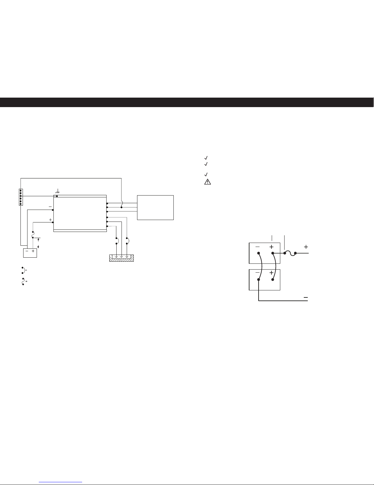
4. CAUTION: For an ABYC E-11 compliant installation, this Inverter must be installed with an inline fuse
in the positive (+) cable on the DC side of the inverter (between the battery and the inverter) at a distance
of seven inches (7”) from the battery connection (Please see Specifications table in this manual for
correct sizing).
Battery Precautions
1) To reduce risk of battery explosion, follow these instructions and those published by battery manufacturer
and manufacturer of any unit you intend to use in vicinity of battery. Review cautionary marking on these
products and on engine.
SPARK - Be very cautious about dropping metal objects such as screwdrivers and wrenches onto a
battery. This could short-circuit the battery and immediately cause a spark that may result in a fire or explosion.
DC Connection Precautions
1) Connect and disconnect DC output connections only after setting any inverter switches to off
and removing AC cord from electric power.
Personal Safety Precautions
1. WORKING IN VICINITY OF A LEAD-ACID BATTERY IS DANGEROUS. BATTERIES GENERATE EXPLOSIVE
GASES DURING NORMAL BATTERY OPERATION. FOR THIS REASON, IT IS OF UTMOST IMPORTANCE
THAT EACH TIME BEFORE SERVICING THE UNIT IN THE VICINITY OF THE BATTERY, YOU READ
THIS MANUAL AND FOLLOW THE INSTRUCTIONS EXACTLY.
2. Never charge or invert power from a frozen battery.
3. If necessary to remove a battery from a vehicle or vessel, always remove grounded terminal from
battery first. Make sure all accessories are off, as not to cause an arc.
4. Be sure area around battery is well ventilated.
5. Clean battery terminals. Be careful to keep corrosion from coming in contact with eyes.
6. Study all battery manufacturer’s specific precautions such as removing or not removing cell caps
while charging and recommended rates of charge.
WEAR - Complete eye protection and protective clothing. Avoid touching eyes while working near battery(s).
NEVER - Smoke or allow a spark or flame within the vicinity of the battery work area.
REMOVE - All personal metal items such as rings, watches, bracelets, etc. when working near a battery.
A battery can produce a short circuit current high enough to weld a ring or any other metal causing serious burns.
WARNING: Restrictions on Use- The TruePower Plus Inverter shall not be used in connection
with life support systems or other medical equipment devices.
DANGER
HIGH VOLTAGE
AVOID SERIOUS INJURY OR DEATH FROM ELECTRICAL SHOCK.
BEFORE PERFORMING ANY ELECTRICAL WORK TURN OFF AC POWER SUPPLY
DANGER
EXPLOSION HAZARD
AVOID SERIOUS INJURY OR DEATH
MAKE CONNECTIONS IN AN ATMOSPHERE FREE OF EXPLOSIVE FUMES
WARNING
LOW VOLTAGE
AVOID SERIOUS INJURY FROM ELECTRICAL BURNS AND SPARKS.
BEFORE PERFORMING ANY ELECTRICAL WORK DISCONNECT ANY DC POWER
SUPPLY FROM UNIT
CAUTION
HOT SURFACES – TO REDUCE RISK OF BURNS DO NOT TOUCH WHILE IN SERVICE
SAFETY INSTRUCTIONS

GENERAL OVERVIEW GENERAL OVERVIEW
5 6
TruePower Plus Overview
The above picture outlines the front of the TruePower Plus Inverter.
Please Reference Table below for features:
1. USB Charge Port
2. AC Output
3. AC Input
4. Two 15A GFCI Protected AC Outlets to power connected appliances.
5. Ventilation Openings provide air circulation for peak performance
6. Ground Stud
3
4
2
1
5
The above picture outlines the back of the TruePower Plus Inverter.
The table below references the above numbered features of the back panel
7. DC Input Cable (Positive +)
8. DC Input Cable (Negative -)
9. Fan Housings keep clear 16 inches
10. Mounting flanges (Side)
11. Remote Port for simple remote with on / off switch and power and fault LED
12. GFCI Breaker
TruePower Plus Overview
12
811
7
10
9
6

GENERAL OVERVIEW GENERAL OVERVIEW
7 8
TruePower Plus Inverter Modes
The TruePower Plus Inverter has 3 distinct modes which allow you to tailor the inverter behavior to
your specific needs:
Pass-through Mode (LCD display is off):
Pass-through mode is indicated by only being lit on the display panel. All other LEDs are off.
- In pass-through mode up to 30A of shore power can be passed through the inverter.
- In this mode if the shore power is interrupted the inverter will not convert DC to AC to keep the loads on.
- DC draw from the batteries is lowest in this mode (<5 ma); which makes this ideal for long term storage.
Stand-by Mode (LCD display is on)(Output supplied by station power, fast transfer to inverting
when needed):
Stand-by mode is indicated by both and the LCD display being illuminated on the display panel.
- Power for the loads connected to the inverter comes from shore power.
- In the event of power interruption the inverter will switch automatically to inverting mode to keep
the loads on. This is ideal for loads like computers where a power dropout could cause lost data.
- DC draw from the batteries is <1A in this mode; which may discharge batteries if they do not have
an external source of charge.
Inverting Mode:
Inverting mode is indicated by and LCD display being illuminated on the display panel.
- Power for the loads is supplied by the attached batteries.
- The unit will automatically switch back to standby mode if AC power becomes present.
AC
AC
DC
12V
On/Off
Input Power
System Status
DC to AC Output
Check
0% 100% 10 VDC 13VDC
DC Input Level
AC
DC
12V
TruePower Plus Display Overview
Inverter Mode
Inverting Standby Pass-through
Output generated from DC Output supplied by shore
(fast transfer to batteries
if needed)
1. DC to AC The LED graph shows the Off Off
Output percentage of the inverters
total DC to AC conversion
capability (0 to 100%). The
final LED turns red when
the unit is overloaded.
2. Input Power
3. DC Input Level When the input DC voltage is below 11 VDC, the first Off
LED is lit red. From 11 to 13 VDC, the LEDs are lit
green and incrementally indicate the battery level.
4. Wrench Symbol The wrench symbol illuminates red when the Off
inverter is in fault condition.
5. System Status The System Status LCD screen shows the status of the Off
inverter. When the inverter is running normal, the LCD
indicates “SYSTEM NORMAL”. If a fault condition occurs,
the LCD screen turns red and display an error message.
6. On / Off button Pushing the button will change to pass-through mode Pushing the button
will change to
Standby/Inverting
mode
1
2
4
3
5
6
AC
DC
12V
AC
On/Off

GENERAL OVERVIEW GENERAL OVERVIEW
USB Charge Port
The USB port on the front panel provides power (5 VDC, 2.1 ADC ) to USB connected devices. The port
can provide power when the inverter is running from DC power or AC shore power. When the port is
not in use, be sure the rubber dust cover is sealed over the port.
910
System Status Fault Modes
All faults conditions are accompanied by a 2 second on / off tone.
Fault Name Explanation
Illuminates red when the DC Input level is below 10.5 VDC
Illuminates red when the DC Input level is below 10.0 VDC
Illuminates red when the DC Input level is above 15.5 VDC
Illuminates red when the internal temperature is above 65 degrees Celsius
Illuminates red when the output power is > 105%
TruePower Plus Remote
The remote allows the user to remotely view inverter status. The blue AC plug symbol indicates when
the inverter is running from AC shore power. The green 12V battery symbol indicates when the inverter
is running from DC power. The wrench symbol illuminates red when the inverter is in fault condition.
The button toggles between pass-through and Standby/Inverting modes.
OVERLOAD SHUTOFF
HI TEMP SHUTOFF
HI DC SHUTOFF
LOW DC SHUTOFF
LOW DC ALARM

INSTALLATION INSTALLATION
Required Tools and Materials
You will need the following to install the inverter unit:
- Two 7/16” box wrenches (1000-1500 watt models)
- Two 1/2” box wrenches (2000 watt models)
- Wire strippers
- Phillips-head screwdriver
- Flat-head screwdriver
- Properly sized DC cabling
- Mounting hardware
Inverter Unit Location
NOTE: On Board Solutions highly recommends that this unit be installed by a Certified Electrical
Technician. Guidance from ABYC E-11 AC & DC Electrical Systems and ABYC A-31 Battery
Chargers & Inverters is offered throughout this manual to ensure a safe, trouble free installation.
Please re-read the PERSONAL PRECAUTIONS section of this manual prior to installation.
This unit must be located in a cool, dry, well ventilated area, free from unsecured hardware. Temperature
is also a serious consideration. Do not mount this unit in an engine compartment or areas where
temperatures will exceed 40°C (104°F).
In addition, the following should be considered when choosing a location:
1) Locate inverter unit away from battery in a separate, well ventilated compartment.
2) Placement of the remote status panel - A length of communications cable is provided for
remote-location of the status/on/off panel. Ensure the cable is long enough to reach the desired
location (generally in proximity to the main panel board) and avoid any area where it can be damaged.
3) Service - Remember, there are items on this unit that should be routinely checked (connections,
LED Status Center) to ensure that there is ample room to address these issues. Also consider
space to adequately swing a standard wrench.
4) Cable Routing - Large DC cables and over current protection (fuses/circuit breakers) will be
located in proximity to this unit. Choose a location as CLOSE AS POSSIBLE to the DC battery
bank serving the unit. This will provide optimum performance for the unit and keep cable sizes smaller.
Location of the AC power is less critical than the DC supply. More information on cable sizing follows.
MOUNTING - This unit must be mounted securely to an appropriate surface (e.g. plywood bulkhead,
cored fiberglass hull structure) and through-bolted if possible.
Preparing for Installation
WARNING: This device is not ignition protected, risk of fire or explosion
This equipment contains components that could produce arcs or sparks. To reduce the risk of fire or
explosion, do not install this equipment in compartments containing batteries, flammable materials or
fumes, or in a location containing gasoline-powered machinery, or joints, fittings, or other connections
between components of the fuel system.
WARNING: Do not mount the inverter above or below your batteries.
WARNING: Electrical shock and fire hazards
On Board Solutions recommends all wiring be done by qualified personnel. Disconnect all AC and DC
power sources to prevent accidental shock. Disable and secure all AC and DC disconnect devices and
automatic generator starting devices. It is the installer’s responsibility to ensure compliance with all the
applicable installation codes and regulations.
WARNING: Installation precaution
The TruePower Plus Inverter should be mounted on a flat horizontal surface or a vertical surface. In no
case should the front or rear end caps be facing in an upward or downward position. This allows proper
ventilation and product safety of the unit as intended by design.
WARNING: Fire hazard
Do not cover or obstruct the ventilation openings. Do not install this equipment in a compartment with
limited airflow; Overheating may result.
WARNING: Risk of fire or explosion
WARNING: Low voltage - electrical burn and spark hazard.
Disconnect battery power before servicing.
NOTE: This unit requires a large amperage draw from a DC battery when in inverter mode. Care must be
taken during installation to provide properly sized cables from the battery to the inverter. Cable runs must
be as short as possible and of the appropriate size and type. See the Installation section for more details.
Installation Recommendations and Requirements Include the Following:
American Boat and Yacht Council (ABYC)
The Canadian Electrical Code (CEC)
Canadian Standards Association (CSA)
The U.S. National Electrical Code (NEC)
RV Industry Association (RVIA)
11 12

INSTALLATION
AC Wiring Options
Installation Diagrams
WARNING - AC Installations have the potential to cause serious injury or death.
Installations should be performed by an ABYC Certified Electrical Technician to ensure
a safe and trouble free installation.
Depending on the appliances and loads that are intended to be powered by the TruePower Plus
Inverter, there are essentially 2 installation options:
1) TRANSFER TO ALL LOADS – This scenario allows the entire AC panel board to be powered
by the TruePower Plus Inverter. This is the simplest installation for an existing AC panel board.
This scenario enables the user to choose what will be powered by the TruePower Plus Inverter.
Energizing the entire panel may overload the unit depending on the size and the load requested.
The diagram below provided from ABYC found in A-31 battery chargers and inverters
Advantages - Multiple loads from the existing panel board can be chosen, the user is not locked
into set loads. This may require more trial and error to determine which loads the TruePower Plus
Inverter can run.
13 14
* Note: Unlike household wiring, the neutral (N) and ground (G) are only connected
together at the SOURCE of power, either inverter or shore/station power. The
TruePower Plus transfer switch maintains this wiring scheme automatically.
TruePower Plus
Inverter
Case Ground/Earth
DC
AC
OUT
AC
IN
DC Positive Fuse
or Breaker Double Pole
AC Main Breaker
Ground
Bus/
Engine
Negative
12V Battery
Connection
Panel
Ground
Bus
Panel
Neutral
Bus
AC Panel
Lights
TV
Coffee Maker
Electric Grill
Microwave
Circuit
Breaker
Shore/
Station
Power
IN
N (White)
G (Green)
L (Black)
G
N
L
N
G
12V Battery
< 7”
(Black)
(Red)
L
INSTALLATION
Fuse

INSTALLATIONINSTALLATION
15 16
Parallel Batteries (12V) for a 12V Bank
(Increases the Amp/Hr Capacity)
Installation
STOP!
BEFORE INSTALLING YOUR INVERTER READ AND FOLLOW THE BELOW CHECKLIST:
Begin with the power switch and main shore/station power breaker in the off position.
Ensure that all overcurrent protection (e.g. fuses and/or circuit breakers) are ready for use, not blown or tripped.
Use great care to ensure the polarity of the DC connections are correct or damage will result to your inverter.
Verify all connections are tight, corrosion free and of good integrity.
DO NOT OPERATE THIS UNIT WITHOUT THE EARTH CONNECTION ATTACHED.
The earth conductor is permitted to be 1 common size smaller than the DC positive (+) conductor
(Example: DC += 2 AWG, Earth = 4 AWG)
12 Volt DC Battery Source- On Board Solutions minimum recommended battery or battery bank
is 200 Ahr. Batteries can be a single battery or multiple batteries in parallel. Batteries connected
in parallel boost amp hours while maintaining voltage.
Tapping each battery as shown balances the load of the battery.
Parallel batteries illustrated:
* Note: Unlike household wiring, the neutral (N) and ground (G) are only connected
together at the SOURCE of power, either inverter or shore/station power. The
TruePower Plus transfer switch maintains this wiring scheme automatically.
AC Wiring Options (Continued)
2) DEDICATED APPLIANCE - This scenario is becoming popular with items like air conditioning
units and refrigerators where the load of the appliance and the rating of the inverter are matched.
With this type of installation, the inverter is dedicated to only one load, whether in invert or pass-
through mode.
Advantages - With this installation type there is never an issue with overloading of the inverter capacity.
TruePower Plus
Inverter
G
N
L
N
G
< 7”
L
Dedicated
Appliance
G
N
L
Case Ground/Earth
DC
AC
OUT
AC
IN
DC Positive Fuse
or Breaker Double Pole
AC Main Breaker
Ground
Bus/
Engine
Negative
12V Battery
Connection
Circuit
Breaker
or Fuse
Shore/
Station
Power
IN
N (White)
G (Green)
L (Black)
12V Battery
(Black)
(Red)
Fuse
< 7”

Installation (Continued)
INSTALLATION MATERIALS – CABLING
Use great care to ensure the polarity of the DC connections are correct or damage will result
to your inverter.
1) DC Cables - The DC portion of the TruePower Plus Inverter requires a large amount of amperage
in Inverter mode. Cable size and length is of extreme importance and should be well thought out
and planned per this manual before beginning installation. Items to consider are as follows:
a. Cable Size - Size is based on amperage draw of the unit compared to the maximum
amperage a cable can carry based on ABYC E-11.On Board Solutions recommends NO
MORE THAN a 10% drop in voltage from source (battery) to the TruePower Plus unit or a
cable run not longer than 5 feet.
The following table outlines the cable size based on a 5’ out and 5’ back (10’ round trip cable run).
Recommended cable sizes (Based on UL 1426 105°C jacket temperature rating & a class T fuse)
b. Termination - Larger DC cables require specialty tools to ensure proper termination with
ring terminals. Pre-terminated cable kits can be purchased through On Board Solutions
or your local marine supply store. Cable type is as important as size. Cables must be
acceptable under ABYC E-11 AC & DC Electrical Systems on Board Boats (types such as
UL 1426 Boat Cable and SAE J1127 Battery Cable are common and marked as such)
c. Connection - The ring terminal must be directly on the battery terminal surface of the DC
studs on the TruePower Plus Inverter, followed by the washer and nut with a torque of
10-15 foot-pounds. The use of a dielectric or anti-oxidant paste is recommended once
the cables have been connected.
d. Strain Relief- Install proper strain relief within 6" of inverter to prevent weight and vibration
of large cables from damaging the inverter.
e. Installing DC Safety Fuse: Install fuse in positive (+) cable within 7” of battery.
See above table for recommended fuse
DO NOT ATTEMPT CABLE TERMINATION BY MEANS OTHER THAN PROPER CRIMPING,WITH A PROPERLY
CALIBRATED TOOL. SOLDER AND AUTOMOTIVE REPAIR TYPE BATTERY TERMINALS ARE NOT ACCEPTABLE.
USE OF ANY OF THESE TYPES OF TERMINATIONS WILL RESULT IN PREMATURE, UNWARRANTIED FAILURE
OF THE TRUEPOWER UNIT.
2) AC Cables – AC Cables should be UL 1426 Boat Cable, per ABYC E-11. This type of cable is
readily available in both 2 and 3 conductor. Size is based on the maximum amperage to be passed
through the cable and unlike DC does not take into account the length of the cable run and voltage
drop. The table below indicates the proper size for AC Cables.
a. AC Connections - Screw terminal blocks have been provided to connect the input and
output AC cables.
17 18
Shore/station power Service Cable Size (AWG) 105°C Insulation
30 amp 10
Wattage 12 VDC Amp Draw 5’ Length Cable Size (AWG) 12V* Recommended Fuse DC Stud Size
1000 100A 4 150A 1/4”
1200 120A 2 175A 1/4”
1500 150A 1 200A 1/4”
2000 200A 00 250A 3/8”
Operation
Inverter Power On and Off
When AC shore power is provided to the AC input of the inverter, the unit operates in pass-through
mode. When AC shore power is not present, the unit will switch over to inverter mode. In this mode,
the AC output can turned on or off by pressing the ON/OFF button on the display panel. With the
remote feature, the inverter can be turned on or off remotely as well. See page 7 for a detailed
explanation of the modes.
GFCI Testing
To test the GFCI, start by plugging a load such as a lamp into the outlet. Press the TEST button
to shut power off to the load. If the load turns off, then this part of the test is a pass. Next, press
the RESET button. If power is restored to the load, then this test is a pass and verifies the
functionality of the GFCI.
Operating the Inverter within the Load Range
Load Type Precautions
Resistive Loads – Be careful with resistive loads that generate heat (toasters, electric stoves, etc.). Due
to the high current drawn by these loads, a typical battery bank would be drained very quickly. Therefore,
it would impractical to run the inverter with these types of loads for an extended period of time.
Motor Loads – Use caution with the type of motor that you connect the inverter. Induction motors
require a much higher startup current than their running current. Since motors vary in their
characteristics, it is best to test the motor load on the inverter. If the motor does not start or loses
power, the inverter should be turned off and the motor removed. If the motor startup current is
too high, the inverter will turn itself off.
Important Notice: FCC Class B Part 15 Notification
NOTE: This equipment has been tested and found to comply with the limits for a Class B digital device,
pursuant to Part 15 of the FCC Rules. These limits are designed to provide reasonable protection against
harmful interference when the equipment is operated in a commercial environment. Operation of this
equipment in a residential area is likely to cause harmful interference in which case the user will be
required to correct the interference at their own expense. If in a residential setting you are encountering
interference with TV and Radio reception while NOT in inverter mode, then: simply disconnect AC power
from the TruePower Plus Inverter to confirm if this unit is causing the interference, if so explore the
following options to minimize interference:
1) Make sure your AC connections include a proper ground connection
2) Reposition your receiving antenna
3) Purchase a separate AC line filter
4) Relocate the affected appliance so it is further separated from the TruePower Plus Inverter
This equipment has been designed to comply with:
- American Boat & Yacht Council A-31 Battery Chargers and Inverters
- FCC Class B
- Underwriters Laboratories: Standard 458 Power Converter/Inverter Systems for
Land Vehicles and Marine Crafts
- Certified to CSA STD. C22.2 No. 107.2
INSTALLATION OPERATION

MAINTENANCE
Maintenance
Battery Maintenance
Periodically, check the batteries to make sure they are good condition. Check the terminals for
corrosion and clean them with a wire brush if necessary. If the batteries are flooded lead-acid,
check the electrolyte levels every month and top off with distilled water if needed. Finally, check
the battery voltage in accordance with the manufacturer’s specifications.
Inverter Maintenance
Little maintenance is needed to keep the TruePower Plus Series inverter running properly. To
keep the unit running optimally, you should:
- Wipe the unit’s exterior with a damp cloth to clean off dust buildup.
- Check that the DC cables are securely connected and the fasteners are tight.
- Clear the ventilation holes of dust buildup.
- The GFCI outlet must be tested monthly. See page 18 for proper GFCI testing procedure.
Troubleshooting
WARNING
ELECTRICAL SHOCK HAZARD
Do not disassemble the TruePower inverter. It does not contain any serviceable parts and
attempting to service the unit could result in an electrical shock or burn.
Failure to follow these instructions can result in death or serious injury
How to Troubleshoot Common Fault Conditions
This section details how to troubleshoot the TruePower Plus Series Inverter. Follow the process below to
narrow down the cause of unit fault conditions. Go through this process before contacting customer service.
1. Check for any fault messages on the unit display screen. If a fault message is displayed,
note it down before proceeding further.
2. Note the conditions around the time the fault condition occurred. Record the following details:
- Battery voltage at the time of failure
- How many watts the inverter was putting out
- Extreme environmental factors (ambient temperature, vibrations, moisture, etc.)
3. If no fault messages are displayed, check the installation:
- Is inverter properly mounted and located in a clean, dry, adequately ventilated environment?
- Is the battery in good condition?
- Are the DC and AC cables properly sized, in good condition, and have clean and tight connections?
- Have any circuit breakers tripped?
- Have any fuses blown?
4. When steps 1 through 3 have been completed, contact customer service for further troubleshooting.
Be prepared to provide information surrounding the unit failure as well the unit model and serial number.
19 20
TROUBLESHOOTING
Condition
Battery voltage has
fallen below 10.5 V
+/- 0.5 V
Battery voltage has fallen
below 10.0 V +/- 0.5 V and
inverter output is shutoff
Battery voltage is above
15.5 V +/- 0.5 V and
inverter output is shutoff
Inverter internal
temperature is above
> 65 C and inverter
output is shutoff
Inverter output is
greater than 105%
and is shutoff
Action
- Check battery voltage and recharge if needed
- Check for proper DC cable sizing
- Check for loose connections and tighten if needed
- Charge batteries to clear fault
- Check battery voltage and recharge if needed
- Check for proper DC cable sizing
- Check for loose connections and tighten if needed
- Charge batteries to clear fault
- Check for other DC inputs, such as an over
voltage alternator, and disconnect if needed
- Decrease input voltage to clear fault
- Reduce the loads connected to the unit AC output.
- Check for proper ventilation to the unit and remove
any obstructions
- Check the ambient temperature and move the
unit to a cooler location if possible
- Push button twice to clear fault
- Reduce the loads connected unit AC output
- Check for loads that have a high surge & remove if needed
- Push button twice to clear fault
Fault Message
LOW DC ALARM
LOW DC SHUTOFF
HI DC SHUTOFF
HI TEMP SHUTOFF
OVERLOAD SHUTOFF

SPECIFICATIONS
TRUEPOWER PLUS - TWO YEAR LIMITED FACTORY WARRANTY
Each product is guaranteed against defects in material and workmanship to the original consumer in
normal use for two full years from the date of purchase. On Board Solutions at its discretion will repair
or replace free of charge any defects in material or workmanship.
The following conditions apply:
• Warranty is calculated from date of manufacture if not registered within two weeks of sale.
• Water intrusion will damage unit and void warranty.
• Reverse polarity connection will damage unit and void warranty
• Warranty void if damage occurs due to negligent repairs.
• Customer is responsible for returning the product to On Board Solutions.
Inbound shipping costs must be prepaid.
• This warranty does not cover blemishes due to normal wear and tear or damages
caused by accidents, abuse alterations or misuse.
Purchase or other acceptance of the product shall be on the condition and agreement that On
Board Solutions SHALL NOT BE LIABLE FOR INCIDENTAL OR CONSEQUENTIAL DAMAGES OF
ANY KIND. (Some states do not allow the exclusion or limitation of consequential damages, so
the above limitations may not apply to you.) This warranty is made in lieu of all other obligations
or liabilities on the part of Onboard Solutions. Additionally, On Board Solutions neither assumes
nor authorizes any person for any obligation or liability in connection with the sale of this product.
This warranty provides to you specific legal rights and you may also have other rights, which vary
from state to state. This warranty is in lieu of all other, expressed or implied.
21
Specifications
1000 1200 1500 2000 2000
1000 Watts 1200 Watts 1500 Watts 2000 Watts 2000 Watts
2000 Watts 2400 Watts 3000 Watts 4000 Watts 4000 Watts
Pure Sine Modified Sine Modified Sine Modified Sine Pure Sine
TruePower Plus Model
Continuous Output Power
Surge Rating
Output Waveform
Dimensions
Weight
12.4” x 9.9” x 4” 11.5” x 9.9” x 4” 12.4” x 9.9” x 4” 14.2” x 10.7” x 4.4” 15.5” x10.7” x4.4”
8 lbs 7 lbs 7 lbs 11 lbs 11lbs
DC Input
Operational Voltage Range 11.0 - 15.0 VDC
Nominal Voltage 12.5 VDC +/- 0.5 V
High Voltage Shutdown 15.5 VDC +/- 0.5 V
Low Voltage Shutdown 10.0 VDC +/- 0.5 V
Low Voltage Alarm 10.5 VDC +/- 0.5 V
Low Voltage Recovery 12.0 VDC +/- 0.5 V
Reverse Polarity Protection Via internal fuse (not end user serviceable)
System Off/LCD Off Drain < 5 ma
System Standby/LCD On < 1 Amp
AC Output
Output Voltage 115 VAC +/- 10 V
Output Frequency 60 Hz +/- 3 Hz
Pass-through Voltage Range 100 – 130 VAC
Pass-through Current 30 A RMS
Transfer Time < 30 mS
Efficiency > 90 %
Integrated GFCI Duplex Outlet 15 ACircuit Breaker Overload /
Over Temperature Manual AC re-power to recover Recovery
Short Circuit Recovery Shutoff output voltage, auto recover when short is removed
USB Output
Voltage 5 VDC +/- 5%
Current 2.1 ADC
Environmental Specifications
0 - 40 C
Operating Temperature
Storage Temperature
Operating Humidity
Storage Humidity
-20 to 60 C
10 - 90% non-condensing
10 - 95% non-condensing
22
WARRANTY
When it comes to quality boat parts & hardware, ProMariner is the brand you can depend on.
This manual suits for next models
4
Table of contents
Popular Inverter manuals by other brands

Weather X
Weather X RPS8807DT instruction manual

Generac Power Systems
Generac Power Systems Guardian 04389-1 Installation and owner's manual

Omega
Omega OTEC IEWH Series Technical manual

Haier
Haier N-Series Service manual

Schletter
Schletter FixGrid18-100 Mounting instructions

Champion
Champion QUICK START 200929 quick start guide

Huawei
Huawei iSitePower-M V100R002C00 user manual

Siemens
Siemens SINAMICS G120P Hardware installation manual

Ingeteam
Ingeteam INGECON SUN STORAGE 1Play TL Use and Settings

SolarPro
SolarPro VC21 installation guide

Earthsafe
Earthsafe M500 Installation, operation and maintenance manual

Yamaha
Yamaha TX-81Z product manual