MB079. 2 - 1111529 0 Baumer_TDP02-ESL-TDPZ02-ESL_II_DE-EN (20A1)
Table of contents
Table of contents
1General notes ................................................................................................................................................................ 2
2Security indications ..................................................................................................................................................4
3Preparation .....................................................................................................................................................................5
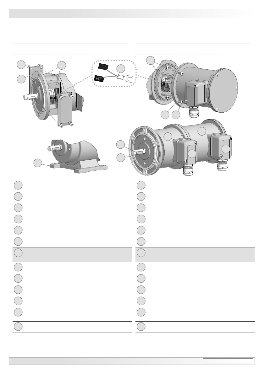
3.1 Scope of delivery device ............................................................................................................................5
3.2 Scope of delivery terminal boxes ...........................................................................................................6
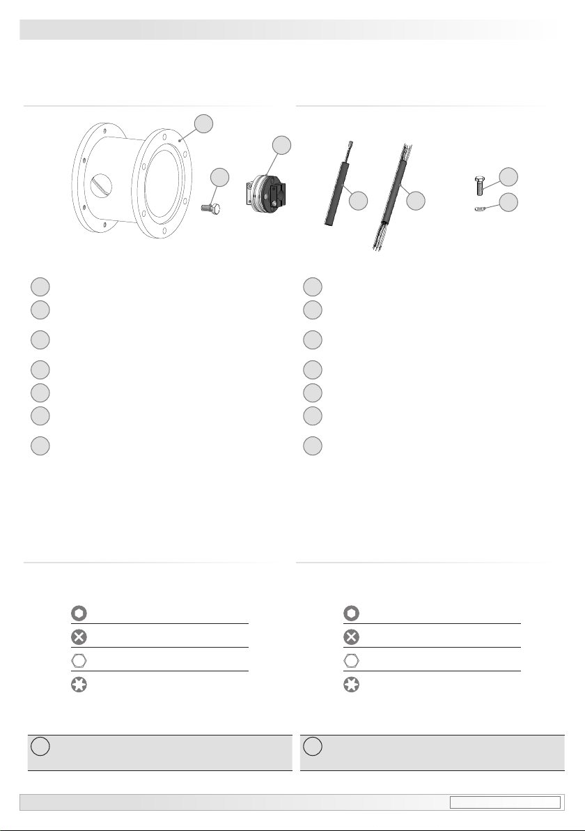
3.3 Required for mounting (not included in scope of delivery) ....................................................... 7
3.4 Required tools (not included in scope of delivery) ........................................................................7
4Mounting ...........................................................................................................................................................................8
4.1 Step 1 ...................................................................................................................................................................8
4.2 EURO ange B10 ...........................................................................................................................................8
4.2 .1 Step 2 ................................................................................................................................................................8
4.2.2 Step 3 ................................................................................................................................................................8
4.2.3 Step 4 ................................................................................................................................................................9
4.3 Housing foot B3 ...............................................................................................................................................9
4.3.1 Step 2 ................................................................................................................................................................9
4.3.2 Step 3 ............................................................................................................................................................. 10
4.4 Mounting instruction .................................................................................................................................. 10
4.5 Maximum permissible mounting tolerance when the
Baumer Hübner K 35 spring disk coupling is used .....................................................................11
4.6 Note when using a jaw-type coupling (for example “ROTEX®”) ........................................ 12
5Dimensions .................................................................................................................................................................. 13
5.1 TDP 0,2 + ESL .............................................................................................................................................. 13
5.1.1 EURO ange B10 ..................................................................................................................................... 13
5.1.2 Housing foot B3 ........................................................................................................................................ 13
5.2 TDPZ 0,2 + ESL ........................................................................................................................................... 14
5.2.1 EURO ange B10 ..................................................................................................................................... 14
5.2.2 Housing foot B3 ........................................................................................................................................ 14
6Electrical connection ............................................................................................................................................ 15
6.1 TDP 0,2 (TDPZ 0,2) ................................................................................................................................... 15
6.1.1 Cable connection ..................................................................................................................................... 15
6.1.2 Connecting terminal TDP 0,2 LT ...................................................................................................... 15
6.1.3 Connecting terminal TDPZ 0,2 LT ................................................................................................... 15
6.2 ESL ..................................................................................................................................................................... 16
6.2.1 Cable connection ..................................................................................................................................... 16
6.2.2 ESL 90 (1 internal relay, 1 switching speed) ............................................................................. 17
6.2.3 ESL 93 (3 relay driver, 3 switching speeds) ............................................................................... 18
6.2.4 ES 93 R Relay modul (accessory) .................................................................................................. 19
7Operation and maintenance ............................................................................................................................. 20
7.1 Replace of the carbon brushes ............................................................................................................ 20
8Dismounting ................................................................................................................................................................ 21
9Accessories ................................................................................................................................................................. 24
10 Technical data ............................................................................................................................................................ 27
10.1 Technical data - electrical ratings ....................................................................................................... 27
10.2 Technical data - electrical ratings (tachogenerator) .................................................................. 27
10.3 Technical data - electrical ratings (speed switches) ................................................................. 27
10.4 Technical data - mechanical design .................................................................................................. 27
10.4 Type data ......................................................................................................................................................... 28
10.5 Replacement switching diagram ......................................................................................................... 28