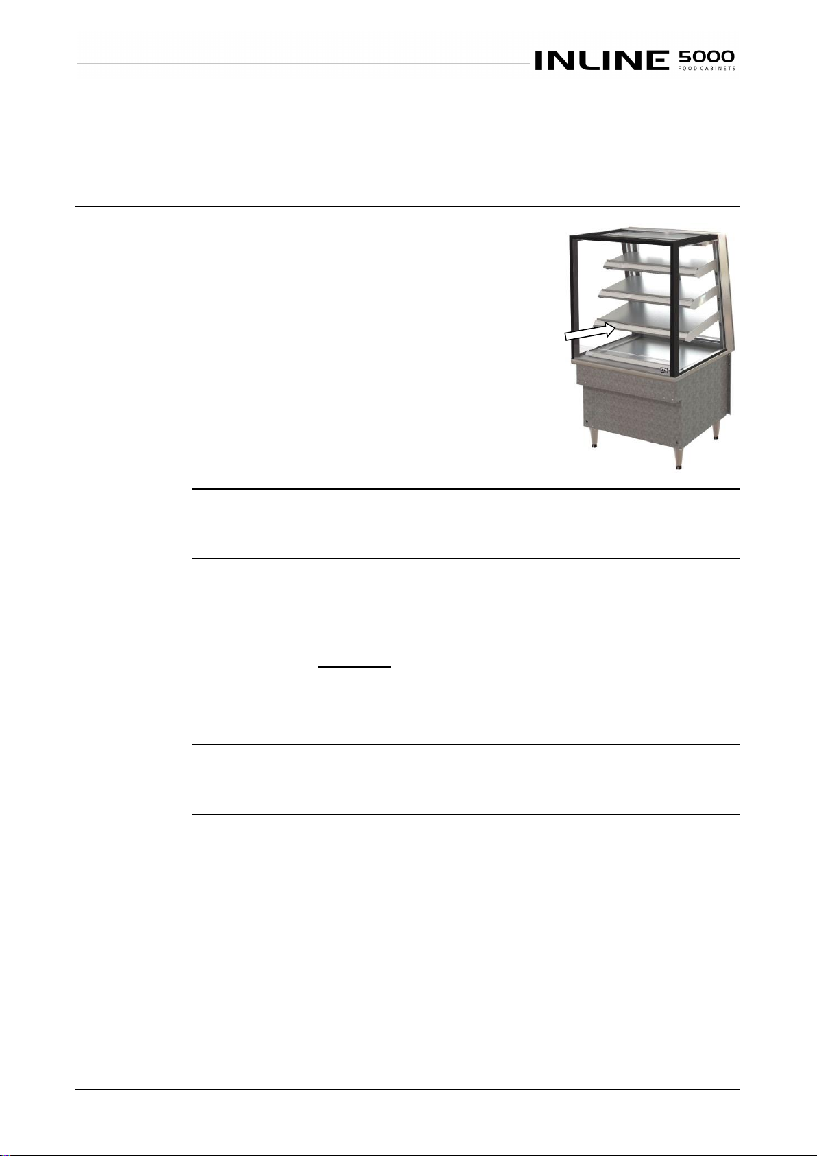
Part No. 27221 Rev. G October 2019 - 4 - 5000 Series Open Front Cabinets
Cleaning Routines ......................................................................................................................................... 13
Schedules................................................................................................................................................. 13
Inspection ................................................................................................................................................. 13
Correction................................................................................................................................................. 13
INSTALLATION ................................................................................................................14
Regulations .................................................................................................................................................... 14
Compliance with Local Requirements...................................................................................................... 14
Setting Up....................................................................................................................................................... 14
Unpacking................................................................................................................................................. 14
Site Preparation........................................................................................................................................ 14
Cabinet Preparation.................................................................................................................................. 14
Location.......................................................................................................................................................... 14
Operating Environment ............................................................................................................................ 14
Access...................................................................................................................................................... 14
Power Supply................................................................................................................................................. 15
Power Supply Connection........................................................................................................................ 15
Electrical Isolation..................................................................................................................................... 15
Earthing .................................................................................................................................................... 15
Mains Lead ..................................................................................................................................................... 15
Lead Replacement ................................................................................................................................... 15
SERVICING.......................................................................................................................16
Gaskets........................................................................................................................................................... 16
Rubber Gaskets........................................................................................................................................ 16
Control Gear................................................................................................................................................... 16
Caution ..................................................................................................................................................... 16
Access to Control Gear ............................................................................................................................ 16
Control Gear............................................................................................................................................. 16
Heating Controls....................................................................................................................................... 16
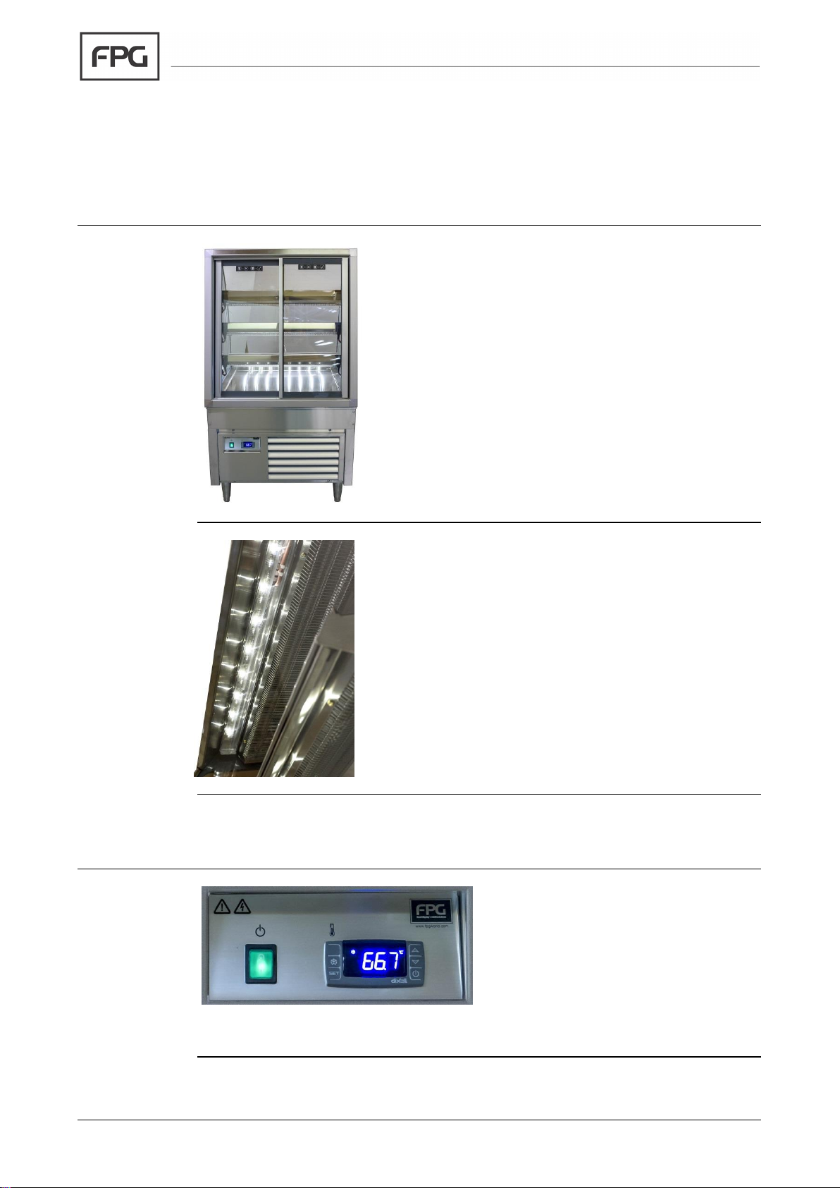
Lighting........................................................................................................................................................... 17
Test Lighting Components ....................................................................................................................... 17
Remove Shelf........................................................................................................................................... 17
Access to LED Strips................................................................................................................................ 17
LED Strip Replacement............................................................................................................................ 17
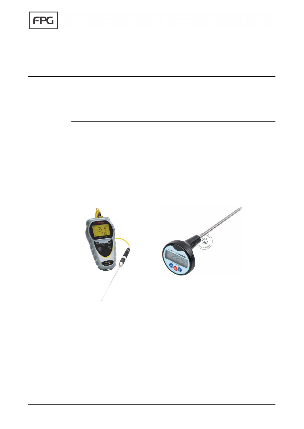
Element Failure.............................................................................................................................................. 18
Alarm Indication........................................................................................................................................ 18
Correction................................................................................................................................................. 18
Servicing................................................................................................................................................... 18
Element Replacement ................................................................................................................................... 18
Remove Cover Plates .............................................................................................................................. 18
Remove Grille........................................................................................................................................... 19
Replace Element...................................................................................................................................... 19
Check Operation....................................................................................................................................... 19
Dixell Controller............................................................................................................................................. 20
Temperature Regulator XR20CX ............................................................................................................. 20
XR20CX Connections .............................................................................................................................. 20