SR-DE103, 183 / SR-MS103, 183
- 9 -
4. TROUBLESHOOTING
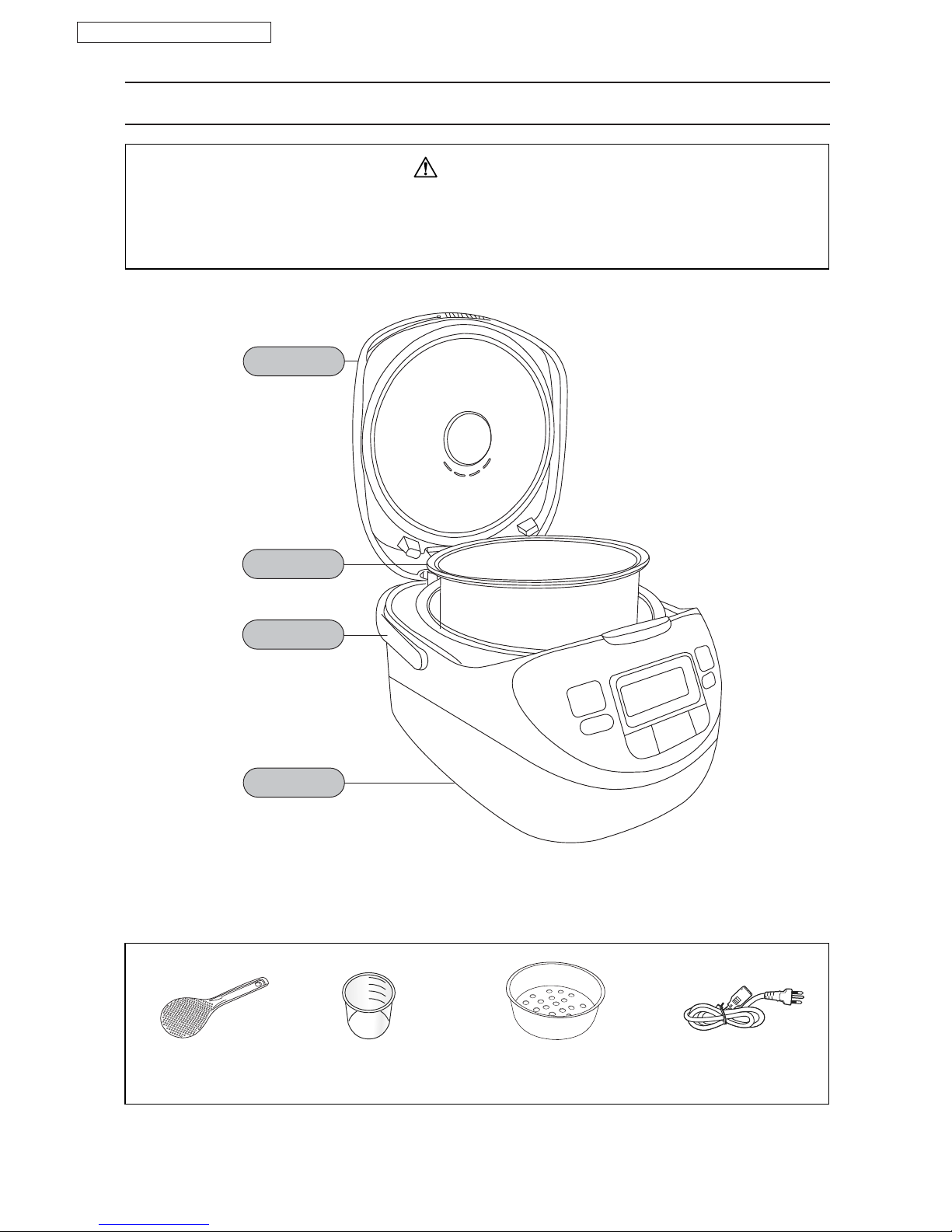
Before repairing the warm jar from users, please confirm whether it is complete (pan, lid, keep warm pin, etc.)
and inquiry the user for specific malfunctions. Please turn off the power before checking the circuit or
component.
Troubleshooting will be proceeded in two steps, one for the main unit and the other for control circuit board.
Please refer to part I before any checking. If the malfunctioned item is unavailable in the troubleshooting
table, please proceed the basic test to check the control circuit board (refer to page 7). Then decide proper
measures according to the troubleshooting description in part II.
The malfunctioned component and its location are indicated in the right side of trouble symptom.
Each component is designated with a number of checking sequence, please refer to it. Please refer to page 7
for information of diagnosing the malfunctioned parts on panel (for reference only).
4.1 Before troubleshooting
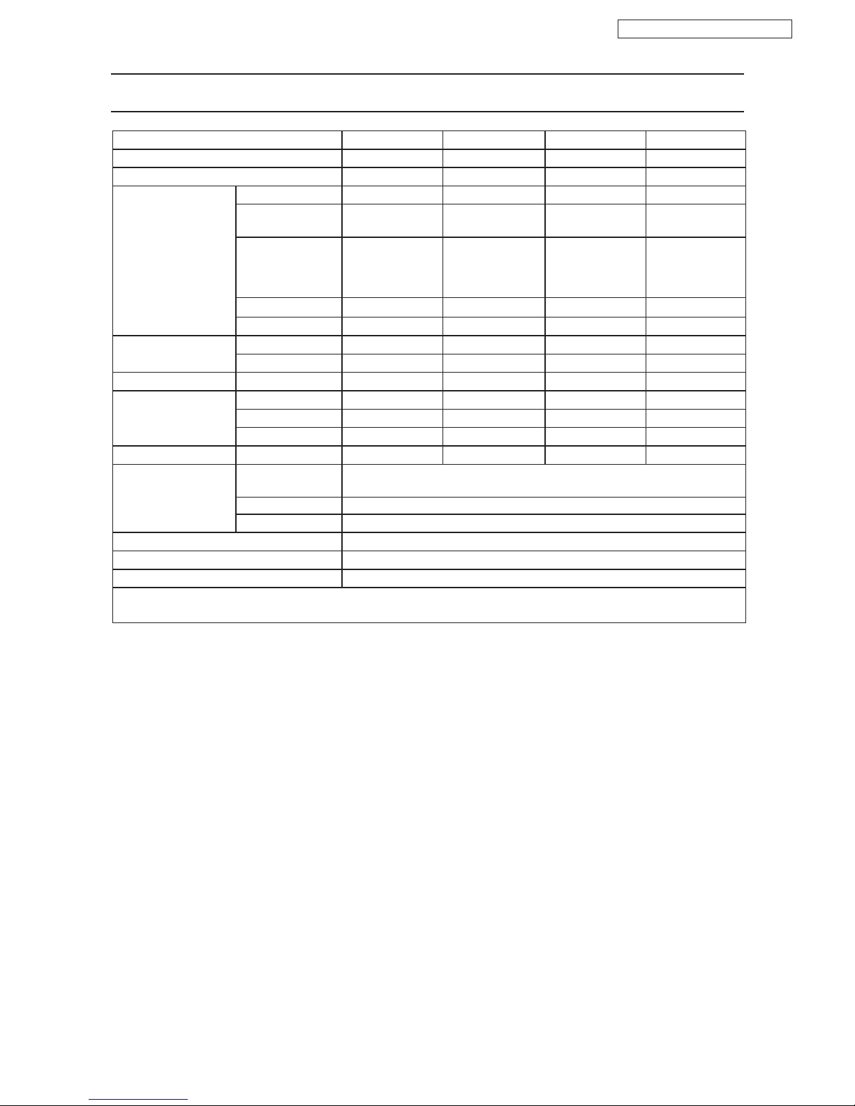
4.2 Self-diagnosing
Display
Symbol Symptom
The “Keep Warm” function is cut off
automatically when the operation
exceeds 96 hours.
All the buttons are inoperative.
Press [ Keep Warm / Off ] button to resume keeping
warm (Do not set keeping warm for more than 12 hours).
Replace the pan sensor (pan sensor is broken off), or
check the branch component of pan sensor on the
computer panel.
All the buttons are inoperative. Replace the pan sensor (pan sensor is broken off), or
check the branch component of lid sensor on the
computer panel.
All the buttons are inoperative. Replace relay or P.C.B. (Cause : The relay is in fault).
Remedy
Precautions for operating microprocessor or control circuit
• The handling personnel should be well grounded.
• The iron should be grounded. Do not use the iron with poor insulation. The iron with microcomputer control
is suggested.
• Do not touch the IC pin or other components before grounded. Do not put the circuit board on conductive
surface that may be charged.
• Do not insert the components from reverse side of the circuit board.
• Do not apply high resistance (x10k) when proceeding continuous measurement with multi-meter, otherwire,
the IC and other components on the circuit board may be damaged due to the high voltage.
• Try to shorten the welding time (within several seconds).
• Please turn off the power before replacing any component.
• The transformer for control panel has a voltage of AC 110V, 120V, 220V, 230V, 240V, so please take care
when handling the electric control board to avoild electric shock or hurt.
The microcomputer is composed of CMOS digital IC and MOS FET, so it is quite sensitive to electrostatic,
such as electrostatic from body, clothes, iron, etc. Please handle it carefully as per following instructions :
The following symbols will appear on LCD automatically when it is abnormal.