1. Safety instructions
During any operation (manipulation) do not
leave the handler position, particularly when
the machine is in operation.
Climbing to the farm equipment during work
or transport is not permitted.
If there is clogging of the tiller (equipment),
shut down the engine and clean the tiller
(equipment) with the appropriate tools.
If there is a damage to motor hoes or
equipment, immediately turn off the engine
and repair.
If there are problems with steering, stop
immediately and turn off the motor
hoes. Repair immediately.
To prevent slipping of the motor hoes on
slopes, you need an assistant who will, by
using a rope or rod, hold the machine. This
person must be at the higher place than the
machine and at a safe distance from the
operating elements.
If possible, always work horizontally to the
slope.
End of work
Never leave the motor hoes unsecured with
the engine running.
Before leaving the machine, turn off the
engine and then turn off the fuel tap.
Secure the motor hoes against unauthorized
use - remove the spark plug cable.
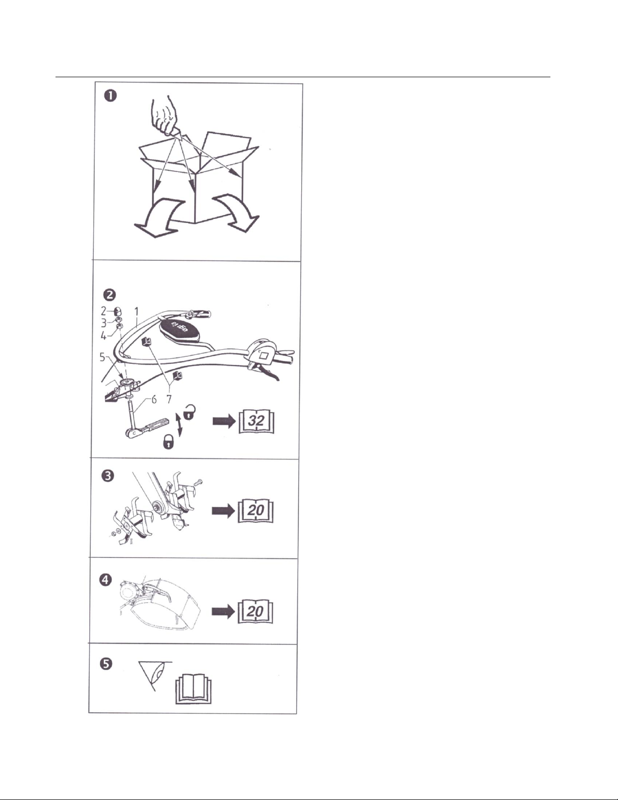
Additional equipment
Mount additional equipment only when
the engine and the drive are off. Always
use appropriate tools and protective
gloves when changing equipment or
parts.
For assembly and disassembly, use the
support devices to bring the motor hoes in
a convenient and stable position.
Secure the motor hoes and equipment
against rolling (use the supporters).
Beware of injuries when mounting
equipment, be very careful.
Mount the equipment as specified in the
instructions and connect them with the
motor hoes only at the designated points.
Secure the motor hoes and equipment
from unauthorized use and rolling when
you leave the machine.
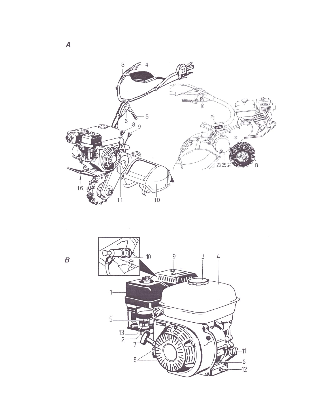
Additional equipment –tiller
Set the tiller hood so that only those parts
(hoes) tilling the soil are not covered.
When tilling (cultivating), make sure that
the slider is set up correctly.