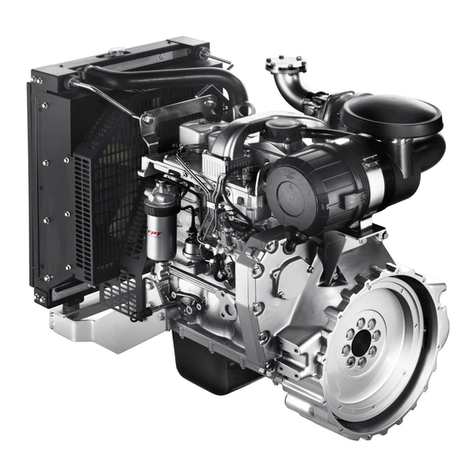
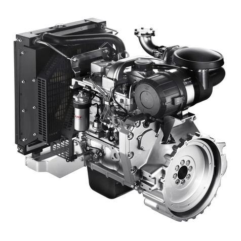
FPT CURSOR Series Operating instructions

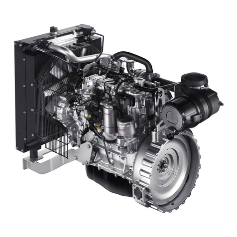
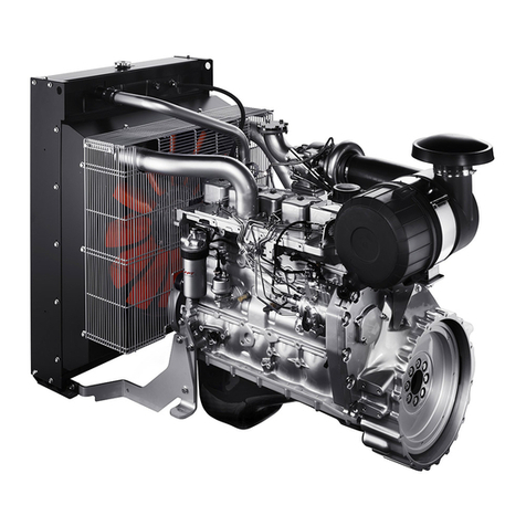
CURSOR 13
NON EMISSIONS
CERTIFIED
Power generation
CR13 TE 7W
F3HFA615A*D001
CR13 TE 6W
F3HFA615B*D001
Technical repair manual

Publication edited by:
FPT Industrial S.p.A
Via Puglia 15, 10156 Torino, Italia
www.fptindustrial.com
Print P4D32C006 E - 1st Ed. 03.2015
This document provides data, specifications, instructions and
methods to perform repair interventions on the assembly and
its components.
Anyhow, this document is addressed to qualified and special-
ised personnel.
Before performing any intervention, check that the document
relating to the vehicle model on which the intervention is being
performed is available and also make sure that all accident pre-
vention devices, including but not limited to, goggles, helmet,
gloves, shoes, as well as work equipment, lifting and transport
equipment, etc., are available and efficient, and also make sure
that the vehicle is in safety conditions for intervention.
Making interventions strictly observing the indications given
here, as well as using specific equipment indicated, assures a
correct repair intervention, execution timing observance and
operators’ safety.
Each repair intervention must be finalised to the recovery of
functionality, efficiency and safety conditions that are provided
by Iveco.
Each intervention on the vehicle that is finalised to a modifica-
tion, alteration or anything else which has not been authorised
by FPT relieves FPT of any liability, and, in particular, where the
assembly is covered by a warranty, each intervention will
immediately invalidate the warranty.
FPT declines any liability for repair work.
FPT is available to provide any information necessary for the
implementation of the interventions and to provide instruc-
tions for any cases and situations not covered in this publica-
tion.
The data contained in this issue may not be up-to-date due to
possible modifications made by the Manufacturer for technical
or commercial reasons, or to adaptations required by laws in
force in different countries.
In the event of discordance between the information in this
publication and the actual assembly, please contact the FPT
network before performing any interventions.”
The complete or partial reproduction of the text or illustra-
tions herein is forbidden.
1
CURSOR SERIES
Print P4D32C006 E Base - 03/2015
Introduction
Section
GENERAL INFORMATION 3................
SYMBOLS 3..............................
-Warnings 3.............................
-Service operations 3......................
GENERAL WARNINGS 5...................
GENERAL WARNINGS
REGARDING THE ELECTRICAL SYSTEM 7..
-Grounding and screening 8.................
CONVERSIONS BETWEEN THE MAIN UNITS OF
MEASUREMENT OF THE INTERNATIONAL SYSTEM
AND THE
MOST COMMONLY USED DERIVED SIZES 9
PAGE HEADER
AND FOOTER INTERPRETATION 10.......

2CURSOR SERIES
Base - 03/2015 Print P4D32C006 E

Manuals for repairs are split into Parts and Sections, each one of which is marked by a number; the contents of these sections are
indicated in the general table of contents.
Sections with mechanical contents include technical data, tightening torque collections, tool lists, assembly connections - disconnec-
tions, overhauls at the bench, troubleshooting and scheduled maintenance.
On sections or parts of the electric/electronic system section there are the descriptions of the electric network and the electronic
systems of the assembly, wiring diagrams, electric characteristics of components, component codes and troubleshooting relative
to the control units specific to the electric system.
Section 1 describes the engine operation and its general features.
Section 2 describes the type of fuel supply and the engine operating diagrams.
Section 3 refers specifically to the electrical equipment and regards wiring, electrical and electronic appliances which differ depen-
ding on use.
Section 4 describes scheduled maintenance and specific overhauling.
Section 5 deals with removal-refitting operations of the main components of the engine.
Section 6 describes the general mechanical overhaul of the engine fitted on the rotating stand.
Section 7 provides the technical specifications of the engine such as data, fitting clearance and tightening torques.
Section 8 deals with the equipment required for carrying out the operations.
The appendix provides a list of the general safety regulations which all operators, whether installers or maintenance technicians,
must comply with to prevent any serious injury.
The manual uses proper symbols in its descriptions; the purpose of these symbols is to classify information. In particular, a set of
symbols has been defined to classify warnings, while another set has been specified for service operations.
General danger
Includes the dangers of both above described signals.
Risk of serious damage to the assembly
The partial or total non-observance of these instructions could cause serious damage to the assembly and may nullify
the warranty.
Environmental protection
Indicates correct behaviour in order for the assembly use to be as environmentally friendly as possible.
Danger for persons
Missing or incomplete observance of these prescriptions can cause serious danger for persons’ safety.
SYMBOLS - Warnings
Indicates an additional explanation for a piece of information.
!
NOTA
GENERAL INFORMATION
Service operations
Example:
α
Tighten to torque
Tighten to torque + angle value
Ø 1 = Housing for connecting
rodsmallendbush.
Ø 2 = Housing for connecting
rod bearings
Ø1
Ø2
3
CURSOR SERIES
Print P4D32C006 E Base - 03/2015

4CURSOR SERIES
Base - 03/2015 Print P4D32C006 E
Removal
Disconnect Intake
Refitting
Connect Exhaust
Disassembly
Dismantling Operation
Assembly
Assemble ρCompression ratio
Tighten to the specified torque Tolerance
Weight difference
α
Tighten to the specified torque + angle value Rolling torque
Press or caulk Rotation
Registration
Adjustment
Angle
Angle value
Visual check
Fitting position check Preload
Measuring
Valuetobefound
Check
Revolutions per time unit
Tools Temperature
Surface for machining
Finished workpiece bar Pressure
Interference
Forced assembly
Oversized
Oversized by no more than .....
Max.
Clearance
Shim
Undersized
Undersized by no more than.....
Min.
Lubricate
Moisten
Grease
Selection
of oversizing
class
Coolant
Sealant
Temperature < 0oC
Cold
Winter
Bleeding air
Temperature > 0oC
Hot
Summer

GENERAL WARNINGS
The warnings shown may not be representative of all the dangerous situations that may occur. Therefore, supervisors
should be contacted whenever a dangerous situation that has not been described occurs.
Use both specific and general-purpose toolings according to the prescriptions contained in respective use and mainte-
nance handbooks. Check the working condition and suitability of tools not subject to periodic review.
The manual handling of loads must be assessed in advance since it also depends not only on weight but also on its size
and on the path.
Handling by mechanical means must be with hoisters proper as for weight as well as for shape and volume. Hoisters,
ropes and hooks used must show clear indications regarding maximum acceptable carrying capacity. The use of such
tools is strictly permitted by authorised personnel only. Stay at a safe distance from the load and never below it.
In disassembly operations, always observe the provided prescriptions and prevent any mechanical parts being taken out
from accidentally striking workshop personnel.
Shop activities performed by two technicians must always been executed with caution; avoid operations that may be
dangerous for any collaborators due to lack of field of vision or incorrect position.
Keep any personnel not assigned to the operations clear of working area.
Learn the necessary concepts of operation and safety relating to the vehicle prior to working on it. Scrupulously observe
all safety warnings on the assembly.
Do not leave the assembly in motion unattended during repair work.
When working on an assembly off the ground, make sure that it is resting firmly on the appropriate supporting stands
and that the manual/automatic safety devices are activated in the event of lifting with a hydraulic ramp.
When working on assemblies fuelled with natural gas, in addition to the instructions given in the document, also observe
all the specific safety regulations provided.
Only remove radiator cap when the engine is cold by cautiously unscrewing it in order to let system residual pressure
out.
Flammable fuels and all fluids and liquids must be handled with care, according to the indications provided in the 12 point
cards of harmful materials. Refuelling must be performed outdoors with the engine off, avoiding lit cigarettes, free flames
or sparks, in order to prevent sudden fires/explosions. Adequately store inflammable, corrosive and polluting fluids and
liquids according to what provided by regulations in force. Strictly avoid using containers for food to store harmful liquids.
Avoid drilling or burning pressurised containers and discard cloths impregnated with inflammable substances into suita-
ble containers.
Worn out, damaged or consumable parts must be replaced with original spare parts.
During workshop activities, always keep the workplace clean; promptly free or clean floors of any accidental spills and
stains of liquids and oils. Electric sockets and electrical equipment necessary to perform repair operations must meet
safety rules.
!
5
CURSOR SERIES
Print P4D32C006 E Base - 03/2015

Before overhauling, clean the assemblies and make sure they are integral and complete. Tidy up detached or disassem-
bled parts with their securing elements (screws, nuts, etc.) into special containers.
Check the integrity of the parts that prevent the loosening of screws: split washers, split pins, clips, etc. Self-locking nuts
with nylon inserts must always be replaced.
Avoid contact of rubber with diesel fuel, petrol or other incompatible substances.
Before pressure washing mechanical parts, protect electrical connectors and any control units.
The tightening of screws and nuts should always be carried out according to directions. FPT’s sales and assistance net-
work is available to provide any clarifications necessary to carry out any repair work not covered by this document.
Before welding:
-Disconnect all electronic control units and unplug the power cable from the battery’s positive terminal (connecting
it to the chassis ground) and connectors.
-Remove paint by using proper solvents or paint removers and clean relevant surfaces with soap and water.
-Wait approximately 15 minutes before proceeding with welding.
-Usesuitablefire-resistantprotectionstoprotecthoses or other components in which fluids or other flammable
materials flow when welding.
Should the vehicle be subjected to temperatures exceeding 80C (dryer ovens), remove the electronic control units.
The disposal of all liquids and fluids should be carried out in strict compliance with specific regulations in force.
Wear all required P.P.E and garments when called for by the operation at issue Contact with moving parts may cause
serious injuries. Use suitable, preferably tight-fitting garments and avoid wearing jewellery, scarves, etc.
Do not leave the engine running in workshops not equipped with a pipe to extract exhaust fumes outside.
Do not breathe fumes from heating or welding of paint, as they are harmful; operate outdoors or in well-ventilated areas.
Wear an appropriate respirator in the presence of paint dust.
Avoid contact with hot water or steam from the engine, radiator and hoses as they could cause serious burns. Avoid
direct contact with liquids and fluids inside vehicle systems; consult the 12 remedy points sheet if accidental contact
occurs.
6CURSOR SERIES
Base - 03/2015 Print P4D32C006 E

GENERAL
W
ARNINGS REGARDING THE ELECTRICAL SYSTEM
NOTE
Do not use fast chargers to start up the engine. Start up must only be performed with either separate batteries or special
truck.
Incorrect polarisation of the power supply voltage for the electronic control units (e.g. erroneous battery polarisation)
may damage the components irreversibly.
Disconnect the batteries from the system before recharging them by means of an external unit.
On connecting, only screw connector (temperature sensors, pressure sensors, etc.) nuts to the prescribed tightening
torque.
Isolate the circuit prior to disconnecting the junction connector from an electronic control unit.
Do not directly supply current to components served by electronic control units with rated vehicle voltage.
The cables must be routed in such a way as to be parallel to the reference plane, as close as possible to the chassis/body.
Upon completing work on the electrical circuit, restore the electrical connectors and wiring as originally provided.
When having to operate on the electrical/electronic circuit, disconnect the batteries from the circuit, disconnecting the
chassis earth cable first of all from the negative terminal of the battery.
Before connecting the batteries to the system make sure the latter is well insulated.
Disconnect the external recharging apparatus from the public utility network before removing the apparatus pins from
the battery terminals.
Do not cause sparks to verify the presence of voltage in a circuit.
Do not use a test bulb to check the continuity of a circuit. Only use the appropriate testing devices.
Make sure that the wirings of electronic devices (length, type of cable, location, strapping, connection of screen braiding,
grounding, etc.) conform with the FPT system and that they are carefully restored after repair or maintenance work.
Measurements on the ECUs, jack connections and electrical connections of components must be done only on regular
test lines, with special jacks and jack bushings. Never use improvised equipment like metal wires, screwdrivers, pins or
similar. This may not only cause short circuits, but also damage the jack connectors, resulting in poor contact.
The connectors are shown from cable side. Connector views contained in the manual are representative of cable side.
!
7
CURSOR SERIES
Print P4D32C006 E Base - 03/2015

8CURSOR SERIES
Base - 03/2015 Print P4D32C006 E
Grounding and screening
The negative conductors connected to circuit ground point must be as short as possible and connected in ”star” form, ensuring
that their tightening is done neatly and sufficiently (Figure 1 ref. M).
The following precautions must be observed regarding the electronic components:
— electronic control units must be connected to the system ground when equipped with metal housings.
— The negative cables of the electronic control units must be connected at a circuit ground point, such as dashboard compartment
ground (avoiding ”serial” or ”chain” connections), as well as to the negative terminal of the battery or batteries.
— Even if not connected to the circuit ground/battery negative terminal, analogue ground (sensors) should have optimal insulation.
Consequently, particular care should be given to terminal parasitic resistances: oxidation, clinching defects, etc.
— The metal braid of shielded circuits must be in contact only at the ECU side to which the signal is to be sent (Figure 2).
— In the case of junction connectors, the unshielded section (d) near to the latter must be as short as possible (Figure 2).
— The cables must be routed in such a way as to be parallel to the reference plane, as close as possible to the chassis/body.
1. “STAR” CONNECTIONS OF NEGATIVE CABLES TO THE CIRCUIT GROUND M
2. SHIELDING BY METAL BRAID OF A CABLE TO AN ELECTRONIC COMPONENT - C. CONNECTOR
d. DISTANCE !0
88039
Figure 1
Figure 2

9
CURSOR SERIES
Print P4D32C006 E Base - 03/2015
CONVERSIONS BETWEEN THE MAIN UNITS OF MEASUREMENT OF THE
INTERNATIONAL SYSTEM AND THE MOST COMMONLY USED DERIVED SIZES
Power
1kW = 1.36HP
1kW = 1.34hp
1 HP = 0.735 kW
1 HP = 0.986 hp
1 hp = 0.746 kW
1 hp = 1,014 HP
Torque
1 Nm = 0.1019 kgm
1 kgm = 9.81 Nm
Revolutions per time unit
1rpm=0.1047rad/s
1rad/s=9.55rpm
Pressure
1 bar = 1.02 kg/cm2
1 kg/cm2= 0.981 bar
1bar = 10
5Pa
Temperature
0˚C = 273.15 K
0˚F = 255.37 K
0˚C=32˚F (the conversion factor between Celsius and Fahrenheit is 1:1.8)
The unit HP is converted into hp for simplicity according to a 1:1 ratio
1hp=1CV.
NOTA
Where accuracy is not particularly required:
-the unit Nm is converted into kgm for simplicity according to a ratio of 10:1
1 kgm = 10 Nm;
-the unit bar is converted into kg/cm2for simplicity according to a ratio of 1:1
1kg/cm
2=1bar.
NOTA

10 CURSOR SERIES
Base - 03/2015 Print P4D32C006 E
Type
of engine
Section
title
Page
number
Number of
printed copies
Language
of Publication
Basic edition referring to
closing phase of drafting
month-year
When present, a
month-year update
(Revi) to the basic edition
PAGE HEADER AND FOOTER INTERPRETATION

1
CURSOR SERIES
Print P4D32C006 E Base - 03/2015
CURSOR SERIES STAGE IV
CURSOR SERIES TIER 4B
Section
General information 1
Operating diagrams 2
Electricl equipment 3
Scheduled Maintenance 4
Removal - Refitting of the main engine components 5
General mechanical overhaul 6
Technical specifications 7
Tools 8
Standard safety precautions Appendix

2CURSOR SERIES
Base - 03/2015 Print P4D32C006 E

3
CURSOR SERIES
Print P4D32C006 E Base - 03/2015
UPDATE DATA
Section Section name Description of modification Page Revision date

4CURSOR SERIES
Base - 03/2015 Print P4D32C006 E

SECTION 1 - GENERAL INFORMATION 1
CURSOR SERIES
Print P4D32C006 E Base - 03/2015
SECTION 1
General information
Page
IDENTIFICATION DATA 3..................
CORRESPONDENCE BETWEEN TECHNICAL
CODES AND COMMERCIAL CODES 4.....
PRODUCT TECHNICAL CODE 5............
VPRODUCT COMMERCIAL CODE 6.........
ENGINE VIEWS 7..........................
ENGINE CHARACTERISTICS 10...............

2SECTION 1 - GENERAL INFORMATION CURSOR SERIES
Base - 03/2015 Print P4D32C006 E

SECTION 1 - GENERAL INFORMATION 3
CURSOR SERIES
Print P4D32C006 E Base - 03/2015
IDENTIFICATION DATA
F3HFA615A*D001 - F3HFA615B*D001
225053
Figure 1
A. Serial number - B. Month and year construction date - C. Engine type - D. Engine family name - E. FPT Engine P/N
1. Bar code
(The Bar code contains: Serial number, Manufacturing date, FPT Engine P/N)
3
227744
Figure 2
1. Label position on “gear train cover” - 2. Label position on “cover cylinder head”

CORRESPONDENCE BETWEEN TECHNICAL CODES AND COMMERCIAL CODES
4SECTION 1 - GENERAL INFORMATION CURSOR SERIES
Base - 03/2015 Print P4D32C006 E
Technical codes Commercial Codes
F3HFA615A*D001 CR13 TE 7W
F3HFA615B*D001 CR13 TE 6W
This manual suits for next models
3
Table of contents
Other FPT Engine manuals

FPT
FPT F Series User guide

FPT
FPT C13 ENS M33 Operating instructions

FPT
FPT N45 AM1S User manual

FPT
FPT F32 Series Operating instructions

FPT
FPT CURSOR 87TE4 User guide

FPT
FPT N Series User guide

FPT
FPT NEF Series User guide

FPT
FPT NEF Series User guide

FPT
FPT NEF Series User guide

FPT
FPT NF67TE8W.S550 User guide
Popular Engine manuals by other brands

Isuzu
Isuzu 3LD2 instruction manual

FAW Jiefang Automotive
FAW Jiefang Automotive 485 Operation & maintenance guide

Great Power Engine
Great Power Engine GP-61 owner's manual

Emerson
Emerson PACMotion IC830M21C Installation and user manual

Briggs & Stratton
Briggs & Stratton Vanguard 430000 user manual

Festo
Festo MTR series operating instructions