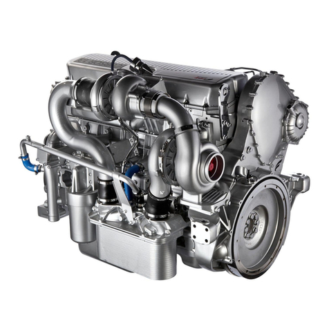
FPT C13 ENS M33 Operating instructions

C13 ENS
M33
C13 ENT M50
TEChNiCal aNd REpaiR
MaNual
JUNE 2007 EDITION
TECHNOLOGICAL EXCELLENCE

1.2 JUNE 2007
C13 ENS M33
C13 ENT M50
FOREWORD
We strongly recommend that you carefully read the indica-
tions contained in this document: compliance with these indi-
cations protects the engine from irregular operation, assures
reliability, safeguards sea-going and protects maintenance
personnel from accident hazards.
The indications contained in this document pertain to the
C13 ENS M33 and C13 ENT M50 marine engines and com-
plement the IVECO MOTORS-FPT “Marine Diesel Engines
Installation Handbook”.You should refer to this for anything
that is not explained herein.
Technical engineers and fitters must comply with work safety
regulations. They must implement and adopt the methods
foreseen for personal safety while carrying out maintenance
or checks.
There is a reminder of the safety rules in Section 11 of the
present publication.
There is a reminder of the regulations for engine handling at
the end of Section 6 of the present publication.
To start the engine, you must adhere to the procedure
stated at the end of Section 5 of the present publication.
To get best engine performance you must conform with its
intended mission profile.The engine must not be used for
purposes other than those stated by the manufacturer.
IVECO MOTORS-FPT is available for a prior examination of
any requirements regarding special installations, should this
be necessary.
In particular
oUse of unsuitable fuels and oils may compromise the
engine’s regular operation, reducing its performance,
reliability and working life.
oExclusive use of IVECO Original Parts is a necessary
condition to maintain the engine in its original integrity.
oAny tampering, modifications, or use of non-original
parts may jeopardize the safety of service personnel and
boat users.
To obtain spare parts, you must indicate:
- Commercial code, serial number and the indications
shown on the engine tag;
- The number of the spare part.This can be found in the
spare part catalog.
The information provided below refers to engine character-
istics current at the date of publication.
IVECO MOTORS-FPT reserves the right to make modifica-
tions at any time and without advance notice, to meet tech-
nical or commercial requirements or to comply with local
legal and regulatory requirements.
We refuse all liability
for any errors and omissions.
The reader is reminded that the IVECO MOTORS-FPT
Technical Assistance Network is always at the Customer’s
side with its competence and professionalism.
IVECO MOTORS-FPT Publication edited by:
IVECO PowerTrain
Advertising & Promotion
Pregnana Milanese (MI)
www.ivecomotors.com
Printed P3D32C002 E- June 2007 Edition
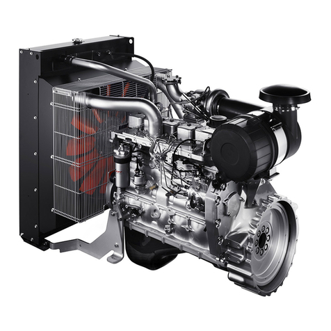
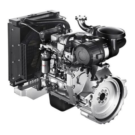
C13 ENS M33
C13 ENT M50
SECTION CONTENTS
Section Page
1. OVERVIEW 5
2. TECHNICAL DATA 35
3. ELECTRICAL EQUIPMENT 41
4. DIAGNOSTICS 67
5. MAINTENANCE 89
6. SERVICING OPERATIONS
ON INSTALLED ENGINE 95
7. TOOLS 113
8. OVERHAUL 125
9. C13 ENS M33 ENGINE 197
10. SAFETY SYSTEM FOR
HOMOLOGATED INSTALLATIONS 209
11. SAFETY REGULATIONS 235
1.3
JUNE 2007
Indications for consultation
The several engine versions are usually explained with
common images and descriptions. In cases of considerable
differences, they are explained separately.
The specific characteristics of the C13 ENS M33 engine
electric system are described in Section 9.
Sections 1-2-3 are intended for sales personnel, to provide
them with an exact knowledge of the product’s character-
istics and enable them to accurately meet the Customer’s
requirements.
The remaining sections are intended for the personnel that
has the task of performing both ordinary and extraordinary
maintenance; by referring carefully to the chapter devoted to
diagnosis, they too will be able to provide an effective service
of technical assistance.

C13 ENS M33
C13 ENT M50
1.4 JUNE 2007
PAGE LEFT INTENTIONALLY BLANK

OVERVIEW 1.5
JUNE 2007 C13 ENS M33
C13 ENT M50
SECTION 1
IDENTIFICATION DATA 7
Identification Tag 7
COMMERCIAL CODE 8
PRODUCT MODEL NUMBER 9
ENGINE PARTS AND COMPONENTS 10
ENGINE ARCHITECTURE 12
COMBUSTION AIR INTAKE
AND EXHAUST SYSTEM 14
Air/sea water heat exchanger 15
Combustion air pre-heating 15
Intake and exhaust assembly 15
COOLING FRESH WATER CLOSED LOOP 16
Tube bundle water/water heat exchanger 17
Bypass junction for thermostatic valve 17
SEA WATER OPEN COOLING LOOP 18
Sea water pump 19
ENGINE OIL - LUBRICATION LOOP 20
Gear pump 21
Oil vapor filter 21
Pre-lubrication system (on request) 21
Commutable filters (on request) 21
FUEL LINES 22
Hydraulic schematic diagram 23
INJECTION SYSTEM - EDC 24
EUI electrically controlled pumping injector 25
Electrical and electronic components 28
System functions 30
Reference signals 32
OVERVIEW
Page

OVERVIEW
1.6 JUNE 2007
C13 ENS M33
C13 ENT M50
PAGE LEFT INTENTIONALLY BLANK

OVERVIEW 1.7
JUNE 2007 C13 ENS M33
C13 ENT M50
Figure 2
The engine identification data are stenciled on a tag positioned over the engine coolant tank.
Figure 1
Identification Tag
Viale dell'Industria, 15/17 - 20010 Pregnana Mil.se MI - ITALY
ENGINE TYPE
ENGINE DWG
ENGINE S/N
COMMERC. TYPE / VERSION
POWER SET CODE
HOMOLOGATION N°
ENGINE FAMILY
POWER (KW)
AND SPEED (RPM)
YEAR OF BUILD
S. p. A.
04_002_N
IDENTIFICATION DATA
05_001_C

OVERVIEW
1.8 JUNE 2007
C13 ENS M33
C13 ENT M50
The purpose of the commercial code is to make it easier to understand the characteristics of the product, categorizing the
engines according to their family, origins and intended application.The commercial code, therefore, cannot be used for technical
purposes and to identify the engine’s components, this is the purpose of the “ENGINE S/N”.
COMMERCIAL CODE
C 13 E NTM50 . 1 0
ENGINE FAMILY IDENTIFIER: C = CURSOR
DISPLACEMENT: 12.880 c.c.
FUEL SUPPLY: E = ELECTRONIC INJECTION
BLOCK: N = NON STRUCTURAL
AIR INTAKE:T = INTERCOOLED SUPERCHARGED
APPLICATION: M = MARINE
MAXIMUM PERFORMANCE LEVEL ACHIEVABLE
50 = 500 HP
VERSION:
TURBOCOMPRESSOR:
1= COOLED
2= NOT COOLED
VERSION

OVERVIEW 1.9
JUNE 2007 C13 ENS M33
C13 ENT M50
PRODUCT MODEL NUMBER
The model number is assigned by the manufacturer; it is used to identify the main characteristics of the engine, and to character-
ize its application and power output level. It is stamped on the side of the crank-case.
F 3 B E 0 6 8 6 C *B
ENGINE FAMILY IDENTIFIER
DESIGN ITERATION
ENGINE
NO. OF STROKES AND CYLINDER DISPOSITION (0 = 4 STROKES,VERTICAL)
NO. OF CYLINDERS
FUEL + INJECTION (8 = DIESEL,TCA, DIRECT INJECTION)
INTENDED USE (6 = MARINE)
POWER RANGE
ACTUAL POWER OUTPUT
VARIANTS TO
BASIC ENGINE
2 0 1

OVERVIEW
1.10 JUNE 2007
C13 ENS M33
C13 ENT M50
ENGINE PARTS AND COMPONENTS
Figure 3
1. Intake air filter - 2. Location of intake air pressure and temperature sensor - 3. Lubricating oil refill cap - 4. Lifting padeyes - 5. CoolantLocation of intake air pressure and temperature sensor - 3. Lubricating oil refill cap - 4. Lifting padeyes - 5. Coolantntake air pressure and temperature sensor - 3. Lubricating oil refill cap - 4. Lifting padeyes - 5. Coolant
level sensor - 6. Engine coolant tank - 7. Coolant refill cap - 8. Injector solenoid valve connector - 9. Location of thermostatic valveEngine coolant tank - 7. Coolant refill cap - 8. Injector solenoid valve connector - 9. Location of thermostatic valve- 7. Coolant refill cap - 8. Injector solenoid valve connector - 9. Location of thermostatic valve
10. Cap for engine coolant outlet to sanitary water heating system 11. Alternator location - 12. Coolant-sea water tube bundle
heat exchanger - 13. Auxiliary pulley - 14. Oil drain sump plug - 15. Sacrificial anodes - 16. Sea water intake - 17. Sea water drain
plug - 18. Air-sea water heat exchanger (not present on the C13 ENS M33 engine) - 19. Sea water pump - 20 Electrical starter
motor - 21. Fuel transfer pump - 22. Fuel filter - 23. Filter clogging sensor - 24. Fuel temperature sensor.
05_117_C
15
6
7
4
8
9
10
11
13
14
17
21
22
23
24
20
3
24
12
1516
18
19

OVERVIEW 1.11
JUNE 2007 C13 ENS M33
C13 ENT M50
Figure 4
1. Coolant feed to exhaust manifold - 2. Lubricating oil filters - 3. Lubricating oil dipstick. - 4. Insulated support - 5. Electronic Central
Unit - 6. Cooled exhaust manifold - 7.Turbocharger inlet pipe-fitting - 8.Timing mechanism and oil vapor filter cover - 9. Location
of timing phase sensor - 10. Oil filter clogging indicator - 11. Cooled turbo-charger - 12. Exhaust gas outlet flange - 13.Waste-gate
actuator - 14. Phase and engine shaft rotation sensor location - 15.Timing phase inspection port - 16.Throttle position sensor
potentiometer - 17. Electrical equipement wiring connectors - 18. Oil fill-in fill-out/pre-lubrication electrical pump (optional) -
19. Oil fill-in fill-out/pre-lubrication electrical pump solenoid valve (optional) - 20. Cap for engine coolant discharge and recyrculation
from sanitary water heating system.
05_118_C
4 5 6 7 8 9
12
13
14
15
16
11
3
2
1
10
17
1819
20

OVERVIEW
1.12 JUNE 2007
C13 ENS M33
C13 ENT M50
ENGINE ARCHITECTURE
With the CURSOR series engines, IVECO MOTORS-FPT
has reached unequalled standards in power delivery for
industrial, marine, and automotive uses; CURSOR engines
are the result of a continuous research process aimed at
product improvement, and they inherit no elements of previ-
ous propulsion units.They adopt the most rational and effec-
tive solutions to achieve, with smaller displacement engines,
power outputs that are typical of larger, heavier engines.
The architecture of these engines is characterized by six cyl-
inders in line, four valves per cylinder and roller rocker arms
with overhead cam shaft and “bonded” block.
Electronic control extended to all functions ensures reliable
and durable operation, offering important benefits in terms
of performance and usage.
IVECO MOTORS-FPT’s contribution to environmental pro-
tection is amply demonstrated by the CURSOR engines’
environmental performance: fumes and noise are well below
current regulatory requirements and compliance with future
limits was the target of the whole design effort.
The 24 valve cylinder head with its camshaft with seven
supports, incorporates the intake manifold and the con-
duits for the cooling and lubrication fluids, as well as for
fuel supply.
The overhead camshaft with roller rocker arms directly
activates both the valves and the EUI (Electrical Unit
Injector).
1. Rocker arm shaft - 2. Intake valve rocker arm -
3. Pump injector rocker arm - 4. Exhaust valve rocker arm -
5. Calibration screw.
Figure 6
1
5432
80877
Figure 5
05_076_C

OVERVIEW 1.13
JUNE 2007 C13 ENS M33
C13 ENT M50
Timing control is to the rear to reduce torsional effects and
it is built with helical tooth gears to contain noise.
Block and sub-block constitute a rigid assembly to reduce
vibration and noise and secure the drive shaft with seven
shaft supports. Aluminum pistons provide effective heat dis-
sipation.
Pump injectors are mounted at the center of the combus-
tion chamber and provide the highest possible thermody-
namic efficiency thanks to an injection that is able to reach
pressures that exceed 1600 bar. Electrically driven by the
electronic control, they deliver fuel at a time that minimizes
fuel consumption and contains gas emissions, while maximiz-
ing torque and power output.
The EDC, Electronic-Diesel-Control system, constantly mon-
itors environmental and engine operating conditions, provid-
ing an optimized injection control to maximize performance
at all times. Even when operating in critical conditions, con-
trol is optimized. This permits navigation and operation to
continue in complete safety.
The electronic unit’s control over the entire engine’s efficien-
cy provides information about the engine’s global perform-
ance and other,specific, information for each cylinder, thereby
making servicing operations easy; associated with the testing
of the working condition of the injection system’s electrical
and electronic components, it stores information about the
most significant events that occur during the engine’s opera-
tion and allows maintenance personnel to anticipate the
onset of faults and resolve them.
80824
80825
Figure 7
Figure 8

OVERVIEW
1.14 JUNE 2007
C13 ENS M33
C13 ENT M50
COMBUSTION AIR INTAKE AND EXHAUST SYSTEM
Description and Operation
Air, drawn in and compressed by the turbocompressor, flows
through the heat exchanger together with sea water. The
latter, by reducing temperature, allows an increase in the
engine’s volumetric efficiency.
The air density at the inlet of the intake manifold is measured
by two sensors, for pressure and temperature, allowing the
ECU of the EDC system to calculate fuel dosage relative to
the actual quantity of air available for combustion.
Lubricating oil vapors (blow-by) not condensed in the sepa-
rator, are sent to the engine intake by a gauged hole down-
stream of the air filter.
Exhaust gas expelled by the engine flows through the cooled
exhaust manifold to reach the turbocompressor rotor
wherein, depending on the supercharging pressure reached,
it may be switched by waste gate to exhaust to limit the
thrust exerted on the turbocompressor rotor and contain
the pressure generated by the compressor within the maxi-
mum rated value.
Exhaust manifold and turbocompressor body are cooled by
the fresh water loop. Exhaust gases flow into the exhaust
terminal and, when provided, they are mixed with the sea
water it carries for overboard discharge.
Figure 9
1. Air filter - 2.Turbocompressor - 3. Exhaust gas manifold - 4. Intake manifold incorporated in cylinder head -
5. Sea water inlet from pump - 6. Air/sea water heat exchanger (not present on the C13 ENS M33 engine).
Intake Exhaust Sea water
80826
2
3
1
45
6

OVERVIEW 1.15
JUNE 2007 C13 ENS M33
C13 ENT M50
Air/sea water heat exchanger
1. Air inlet from the turbocompressor - 2. Outlet for air cooled
by the sea water and destined to the intake manifold -
3. Sea water outlet - 4. Sea water inlet -
5. Condensed water outlet.
Combustion air pre-heating
(not available at the moment)
1. Pre-heating junction - 2. Power relay - 3. Electrical heating
element - 4. Air/water heat exchanger.
Engine start is guaranteed down to -15 °C without the aid
of any pre-heating system. If the engine needs to be used at
lower temperatures, there are provisions (on request) for
the installation of an electrical heating element driven by the
injection system ECU.
When the ECU, through its sensors, recognizes the presence
of a temperature below the prescribed threshold, it will
energize the power relay that controls the electrical supply
to the grid heater.
The heating element will be located at the inlet of the
air/water heat exchanger (after-cooler) after replacing the
overlying junction.
Figure 10 Figure 12
80827
1 2
3
4
5
Figure 11
Intake and exhaust assembly
421 3
05_139_C
1.Turbocompressor supply feeder-line - 2.Waste gate valve command rod. - 3. Command rod guard -
4.Waste gate valve pneumatic actuator.
21
05_061_C
4
3

OVERVIEW
1.16 JUNE 2007
C13 ENS M33
C13 ENT M50
Description and operation
The centrifuge pump,rotated by the drive shaft with a poly-V
belt, draws in the coolant coming from the fresh water/sea
water heat exchanger or from the exhaust manifold cooling
loop and sends it into the block, where it comes in contact
with the lubricating oil heat exchanger. It then touches the
heat exchange areas of the cylinders and subsequently those
of the engine head, from which it exits flowing through the
junction fitting that contains the temperature sensors for the
instrument panel and the injection system.This junction has
the purpose of bypassing the coolant from the engine head
to the exhaust manifold and from the exhaust manifold to
the thermostat - which routes it according to the tem-
perature either to the water/water heat exchanger or to the
recirculation pump.
From the bypass fitting the liquid is then injected into the
heat exchange chamber of the exhaust manifold - through
which it flows going to touch the body of the waste gate, of
a portion the exhaust and of the turbo compressor. When
it returns into the bypass junction it comes in contact with
the wax actuator of the thermostatic valve.This will throttle
flows according to temperature.
Part of the liquid will enter the tank and flow through the
tube bundle heat exchanger, releasing heat to sea water,while
the rest will go directly to the pump, to be recirculated.
COOLING FRESH WATER CLOSED LOOP
Figure 13
High temperature liquid Low temperature liquid
1.Thermostatic valve/coolant tank junction pipe - 2. Coolant tank incorporated in sea water heat exchanger - 3. Bypass junction for
thermostatic valve - 4.Turbocompressor - 5. Cooled exhaust manifold - 6. Engine oil/coolant heat exchanger - 7. Coolant pump -
8. Heat exchanger junction pipe.
1
2
7
8
6
5
4
3
05_140_C

OVERVIEW 1.17
JUNE 2007 C13 ENS M33
C13 ENT M50
1. Bypass flow to engine - 2. Outflow from engine - 3. Outflow from exhaust manifold - 4. Inflow to exhaust manifold -
5. Flow to sea water heat exchanger - 6. EDC temperature sensor - 7.Temperature sensor for the control panel and indicators.
1. Sea water outlet to overboard discharge - 2. Sea water inlet from after cooler - 3. Coolant inlet from thermostatic valve -
4. Coolant outlet to pump.
Bypass junction for thermostatic valve
Tube bundle water/water heat exchanger
80832
1
5
2 3 4
Figure 15
High temperature liquid Sea water
7
6
05_132_C
2
1
4
3
05_077_C
Figure 13

OVERVIEW
1.18 JUNE 2007
C13 ENS M33
C13 ENT M50
Description and operation
Sea water, drawn from under the keel and necessarily fil-
tered, is drawn by the pump and sent to the supercharger
air heat exchanger and from there to the water/water heat
exchanger of the closed cooling loop; only after this will it
flow through the heat exchanger for the gearbox oil, if one
is provided.
The configuration of the discharge lines depends on the
choice of a dry “chimney” exhaust, or a mixed one. The
outlet pipe will carry the water directly to the overboard dis-
charge or, if the water/exhaust gas mixer solution is adopted,
a conduit will connect the outlet of the last heat exchanger
with the mixer inflow junction pipe.
SEA WATER OPEN COOLING LOOP
1. Sea water suction - 2. Sea water pump - 3. Supercharger air heat exchanger (not present on the C13 ENS M33 engine) -
4. Coolant (fresh water) heat exchanger - 5. Sea water outlet from heat exchangers for overboard discharge -
6. Heat exchanger for gearbox oil (on request).
Figure 16
05_080_C
4
6
1
2
3
5
5
Sea water

OVERVIEW 1.19
JUNE 2007 C13 ENS M33
C13 ENT M50
Sea water pump
1. Pump impeller seat - 2. Driving gear shaft -
3. Sea water intake - 4. Sea water delivery.
The sea water pump, centrifugal type, is rotated by the gears
keyed to the rear of the flywheel.
Figure 17
2
4
1
3
05_030_C

OVERVIEW
1.20 JUNE 2007
C13 ENS M33
C13 ENT M50
ENGINE OIL - LUBRICATION LOOP
Description and operation
The gear pump, rotated by the gears at the rear of the fly-
wheel sends the lubricating oil directly to the heat exchanger
which, incorporated in the block and lapped by the coolant,
reduces temperature to maintain optimal lubricating capabil-
ity. The thermostatic valve that regulates oil flow is located
at the inlet of the heat exchanger, opening the bypass pipe if
temperature falls below calibration temperature.
From the output of the heat exchanger, the oil is sent to
the filter assembly and from this back to the engine block to
lubricate all anti-friction elements.
The blow-by vapor condenser, provided with filter and safety
valve, is located on the upper part of the timing mechanism
lid. The vapors, after returning to the liquid state, will flow
from the vapor condensor into the sump. The engine is
provided with the pre-lubrication system on request. This
can inject enough oil into the engine’s ducts to guarantee a
totally safe start.
The operation of the electrical pre-lubrication pump (on
request), is automatically controlled by the ECU electronic
unit.
This system, with the aid of the flow-switching solenoid valve,
also permits the oil sump to be emptied and filled.
Detailed descriptions of this operation are provided in
Section 3.
Figure 18
1. Oil filters - 2. Camshaft on cylinder head - 3. Oil vapor condenser and filter (blow by) - 4.Turbocompressor - 5. Oil pump
safety valve - 6. Lubrication oil pump - 7. Drive shaft - 8.Turbocompressor lubricating oil flow line - 9. Oil return flow from
turbocompressor - 10. Oil sump - 11. Heat exchanger with coolant - 12. Electrical pump for pre-lubrication and oil filling/emptying
(on request) - 13. Solenoid valve for switching between the pre-lubrication or oil filling/emptying functions (on request) -
14. Oil emptying junction - 15. One-way pre-lubrication valve.
Sump return oil Delivery oil
80835
1
15
14
1011 9
12
13
4
5
8
7
6
32
This manual suits for next models
1
Table of contents
Other FPT Engine manuals

FPT
FPT NEF Series User guide

FPT
FPT NF67TE8W.S550 User guide

FPT
FPT N Series User guide

FPT
FPT NEF Series User guide

FPT
FPT F Series User guide

FPT
FPT N45 AM1S User manual

FPT
FPT CURSOR Series Operating instructions

FPT
FPT F32 Series Operating instructions

FPT
FPT NEF Series User guide

FPT
FPT CURSOR 87TE4 User guide
Popular Engine manuals by other brands

GGP
GGP WBE Series Operator's manual

GEIGER
GEIGER SOLIDline-MOR GU4510 operating instructions

Franklin Electric
Franklin Electric 214 Series Assembly and operation instructions

Kubota
Kubota D1703-M-E Operator's manual

Lola&Lykke
Lola&Lykke TJ-CJ-MBB-S Instructions for use

Briggs & Stratton
Briggs & Stratton 300 series Operator's manual