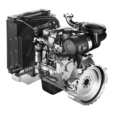
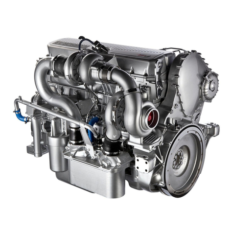
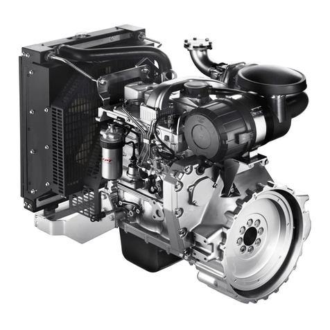
FPT CURSOR 87TE4 User guide

4
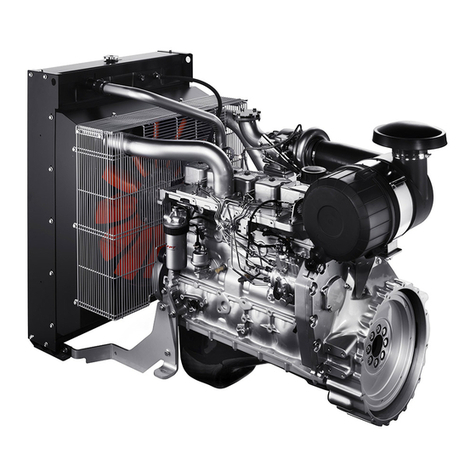
ENGINE TECHNICAL DATA CURSOR 87
The technical code and serial number are indicated on a plate, which
is located on different parts of the engine, according to the model:
flywheel casing, tappet cover, other.
(*)Net power to the flywheel in compliance with ISO 3046-1. Test
conditions: temperature 25 °C; atmospheric pressure 100 kPa;
relative humidity 30%.
Code CURSOR 87
Engine family F2C
Cycle 4-stroke diesel
Number and arrangement
of cylinders 6, in line
Bore x stroke 117 x 135 mm
Total displacement 8,700 cm3
Air system Turbo aftercooler and after-
cooled
Injection type Common Rail
electronically managed
Engine direction
of rotation
Anticlockwise
(seen from flywheel side)
Dry weight (G-Drive) ~ 1050 kg
Electrical system 24 V
Accumulator/s
- capacity
-discharge current
180 Ah or above
1200 A or above
Performance (*) CURSOR 87TE3
Prime 229 kWm @1500 rpm
249 kWm @1800 rpm
Stand-by 249 kWm @1500 rpm
271 kWm @1800 rpm
Performance (*) CURSOR 87TE4
Prime 275 kWm @1500 rpm
306 kWm @1800 rpm
Stand-by 299 kWm @1500 rpm
333 kWm @1800 rpm
WARNING
Any alteration of the above mentioned characteristics, in particular
modification of the data stored in the injection system electronic units
or the characteristics of the engine and its fittings, is strictly prohibited,
penalty invalidation of the guarantee and absence of all liability on the
part of FPT.

5
ENGLISH
CURSOR87TE
1. Lifting eyelet - 2. Air filter - 3. Air delivery duct from filter to
compressor - 4. Lubrication oil filter - 5. Sump oil drain plug -
6. Turbocharger oil return pipe - 7. Heat exchanger - 8. Coupling of
engine coolant return - 9. Radiator - 10. Fan protective grille -
11. Thermostatic valve location - 12. Oil vapour filter seat - 13. Oil
vapour outlet coupling - 14. Exhaust manifold - 15. Turbocharger
exhaust gas outlet - 16. Turbocharger oil delivery pipe -
17. Turbocharger
CURSOR87TE
1. Radiator coolant inlet plug - 2. Engine coolant outlet pipe -
3. Alternator - 4. Intake manifold - 5. ECU - 6. Electric starter motor -
7. Fuel prefilter - 8. Completion kit - 9. High pressure fuel pump -
10. Oil filling cap - 11. Fuel filter
14_021_C
14_022_C

6
CURSOR87TE
1. Compressed air outlet pipe - 2. Turbocharger exhaust gas outlet
pipe - 3. Thermostat assembly - 4. Fan pulley - 5. Guide pulley - 6. Poly-
V belt - 7. Crankshaft damper - 8. Automatic belt tensioner -
9. Alternator - 10. Oil vapour filter - 11. Tappet cover
CURSOR87TE
1. Radiator coolant inlet plug - 2. Air filter - 3. Completion kit -
4. Engine air intake pipe - 5. Engine flywheel - 6. Turbocharger
14_023_C
14_024C

7
ENGLISH
SIGNS
Certain warning signs are affixed to the engine by the Manufacturer,
and their meanings are indicated below.
N.B. The signs with an exclamation mark on them underline a
potential danger.
Lifting point (engine only).
Fuel Cap
(on the fuel tank, if there is one).
Oil Cap.
Oil dipstick.
Danger of burning:
Expulsion of hot water under pressure.
Danger of burning:
Presence of high temperature parts.
Danger of fire:
Fuel present.
Danger of impact or catching
on moving parts:
Presence of fans, pulleys, belts or the like.

8
USE
PRELIMINARY CHECKS
Before starting the engine each time:
Check the level of technical fluids (fuel, engine oil and coolant), and
top-up if necessary.
Make sure that the air aspiration filter is not blocked or obstructed,
checking at the same time that the mechanical indicator on the filter
does not show the “red” sign. If the engine is equipped with an
electrical blockage sensor, an alarm will be displayed on start-up, by
means of the indicator light on the instrument panel.
Note: The procedures required to clean the filter are indicated
in the chapter CONTROLS AND MAINTENANCE.
STARTING AND STOPPING THE ENGINE
The start-up and shut-down operations described below apply to an
on-board control panel manufactured by FPT; if the Manufacturer of
the vehicle or machine has fitted a customised instrument panel, these
operations may vary according to the various choices made during
construction.
In these cases, follow the start-up/shut-down sequences and use the
instrument panel description provided in the specific documentation.
ENGINE PRE-HEATING (optional)
(Electrical device)
The engines for which low temperature start-up and immediate
delivery of power are required may be fitted with a 230 V single phase
electrical heating device, which allows the temperature of the coolant
to be raised to or maintained at suitable values. The device is fitted
with a thermostat to cut the power supply when the required
temperature is reached.
CAUTION!
Make sure that no combustible vapours or gasses are
present in the area in which the engine is to operate.
Ensure that closed areas are adequately ventilated and
fitted with a suitable exhaust extraction system.

9
ENGLISH
INTERCONNECTION ELECTRICAL UNIT
In order to allow the unit’s correct electrical functioning, an
interconnection unit has been fitted to the engine. The engine
electronic control system and the power unit system depend from the
aforesaid interconnection unit.
Some indications relating to its components and functions controlled
by programming commutators are reported here following.
Fuse
F1 Engine start
F2 Diagnosis connector
F3 Fuel heater on filter
F4 Engine electronic control unit
F5 Interface electronic unit
F6 E.C.U. power supply (enabling)
F7/8/9 Reserve
Relays
K1 E.C.U. supply (enabling)
K2 Engine start signal
K3 Engine start
K4 Fuel heater on filter
14_064_C

10
Engine speed and accessory functions control
Programming of the functions here following is possible commuting
the position of the JP switches.
JP1: Engine speed selection
1-2 = 1,800 rev. /min (60 Hz power generation)
2-3 = 1,500 rev. /min (50 Hz power generation)
JP2: Mode selection
1-2 = DIAGNOSIS MODE
2-3 = OPERATING MODE
JP3: Pre-heating warning light
1-2 = connected
2-3 = not connected
JP4: Fuel pre-heating
1-2 = relay on
2-3 = relay off
JP5: It CAN line
1-2 = available
2-3 = unavailable
BP1: Blink code request switch button
LD1: Blink code display
FOR PROPER USE OF THE ENGINE
Before starting the engine, check there is enough fuel in the fuel
tank.
Do not keep on starting.
Do not keep the engine idling for a long while since this has
negative effects to the engine performance.
Actual power values must comply with the rated values reported
in the technical documentation.
When operating the engine, regularly check that:
- the cooling liquid temperature does not exceed the threshold
value;
- the oil pressure keeps within normal values.
Particular attention must be drawn on emergency power unit
engines, which must be submitted to frequent overhauls in order
to ensure their prompt start whenever required.
WARNING
Pay attention to the board panel instrument readings and indications.

11
ENGLISH
SPECIAL WARNINGS
Engine cooling liquid
When the engine is running, regularly check that the engine cooling
liquid temperature does not reach the alarm threshold.
In case the temperature detected is excessive, disconnect the load and
stop the engine to check the cooling circuit status. Wait that the
engine is cold before checking: it is important to remind that, when the
engine is heated, the pressurized hot liquid within the cooling circuits
may be ejected causing burns and serious injury.
Moreover, check the following:
a) the alternator’s belt tension;
b) the thermostatic valve’s efficiency;
c) the conditions of the heat exchanger (to be cleaned if necessary).
Cooling liquid refill
For engine servicing and whenever the system requires significant
cooling liquid refill, proceed as follows:
Refill the engine and the heat exchanger until complete top up.
With the filler cap open, start the engine and keep it idling for nearly
one minute. This phase facilitates the cooling liquid air bleed.
Stop the engine and top up again.
Further information on the cooling liquid technical specifications and
quantity prescribed are reported in the CONTROLS AND
MAINTENANCE section.
Lubrication circuit
Regularly check that the oil pressure keeps within normal values. In
case the value detected is too low, check the oil level and refill if
necessary following the instructions reported in the CONTROLS
AND MAINTENANCE section.
If the failure persists, apply to the Technical Service for assistance.
CAUTION!
Open the cooling liquid tank cap only if it is necessary and
exclusively if the engine is cold.
CAUTION!
Failure to comply with the procedure may cause the
incorrect engine cooling liquid refill and, as a consequence,
wrong quantity within the engine.
12
Fuel circuit
Avoid using the engine with only a small reserve of fuel in the fuel tank;
this encourages the formation of condensation and makes it more
likely you will suck up dirt or air, resulting in engine stoppage.
The common rail injection system does not require air to be bled from
the fuel circuit.
Air intake and exhaust discharge circuits
Inspect the cleanliness of the air intake circuit on a regular basis. The
maintenance intervals indicated in this manual vary according to the
conditions in which the engine is used.
In particularly dusty environments it is necessary to carry out
maintenance at more frequent intervals than indicated in the chapter
CONTROLS AND MAINTENANCE.
Electrical starter system
Periodically check, particularly during the winter, to ensure that the
batteries are clean and in full working order, checking and topping up
as indicated in the chapter CONTROLS AND MAINTENANCE.
Should it be necessary to replace the batteries, always respect the
capacity and minimum discharge current intensity requirements.
CAUTION!
When refuelling, always pay great care to ensure that no
solid or liquid pollutants enter the fuel tank; you must also
remember that smoking and live flames are prohibited
when refuelling.
CAUTION!
Never loosen the high pressure fuel circuit connectors in
any way.
CAUTION!
Visually check that the exhaust circuit is not blocked or
damaged, so as to prevent dangerous fumes.
WARNING!
Contact a specialised workshop and check battery and recharging
system efficiency if the voltmeter indicates a voltage below 11 V (for
12 V rated systems), or 22 V (for 24 V rated systems).

13
ENGLISH
Periodically check or have someone check the cleanliness, wear and full
tensioning of the drive belt.
RUNNING IN
Thanks to modern engine construction technology, no particular
running in procedure is required. However, it is recommended that,
for the first 50 hours, you do not use the engine at high power for long
periods.
CAUTION!
The batteries contain an acid solution that will burn the
skin and corrode clothing; when checking them, always
wear protective clothing, gloves and goggles, do not smoke
or use live flames in the vicinity, and make sure that the
room they are housed in is adequately ventilated.

14
CONTROLS AND MAINTENANCE
MAINTENANCE PERSONNEL
The engine control and maintenance operations described in the
following chapter require training, experience and compliance with
current safety regulations; for this reason they must be carried out by
special technicians, as indicated below.
Controls: by workshop technicians or the machine user if
necessary.
Periodic maintenance: by qualified personnel using
suitable equipment and adequate means of protection.
Special maintenance: by qualified personnel from
Authorised Service Centres who have detailed technical
information and specific equipment.
The most qualified Assistance Centres are those which make up the
FPT Technical Assistance Network.
ACCIDENT PREVENTION
Always wear heavy-duty footwear and overalls.
Never wear loose, flapping garments, rings, bracelets and/or
necklaces in the vicinity of engines or moving parts.
Always wear protective gloves and goggles when:
• filling up batteries with acid solution
• refuelling with inhibitors or antifreeze
• replacing or topping up lubricant (hot engine oil may cause burns
and scalds. Only carry out these operations when the oil has
dropped to a temperature of below 50°C).
When working in the engine compartment, pay particular attention
to how you move, to avoid contact with moving parts or high
temperature components.
Wear goggles and use high pressure air jets (maximum air pressure
used to clean is 200 kPa (2 bar, 30 psi, 2 kg/cm2).
Wear a protective helmet when working in an area were there are
suspended loads or systems installed at head-height.
Use protective hand creames.
Immediately replace wet overalls.
Always keep the engine clean, removing oil, grease and coolant
stains.
Store cloths in flame-proof containers.
Do not leave foreign bodies on the engine.
Use suitable, safe containers for used oil.
When completing a repair, make suitable provisions to stop the
engine taking in air if, after start-up, an uncontrolled increase in
engine speed were to occur.

15
ENGLISH
REFUELLING
(*)The amounts indicated relate to the standard configuration of the
engine only.
(**)Engine with radiator and piping.
(1)Use a mixture of water and 50% glycol even during the summer
months. As an alternative to glycol, use another product that
complies with international specifications SAE J 1034.
(2)Use lubricants that comply with international specifications API
CL4-ACEAE4/E5/E6/E7 5W30.
The viscosity level of oil to be used depending on surrounding
temperatures in given in the table provided in the appendix.
Oil consumption is considered acceptable when it reaches a
maximum of 0.2% of fuel consumption
CAUTION!
Do not carry out maintenance operations when the
electric power supply is turned on: always check to ensure
that the appliances are properly earthed. During diagnosis
and maintenance operations, make sure that your hands
and feet are dry, and whenever possible use insulating
stands.
CAUTION!
The conditions provoking the emergency power unit start
may suddenly occur. Whenever executing checks and
maintenance operations, strictly follow the safety
instructions prescribed by the unit’s Manufacturer and
power unit system’s outfitter to operate safely and prevent
injury.
Parts to be supplied CURSOR 87
litres (kg)
Cooling circuit (1) engine (*) 15 (13.5)
G-Drive (**) 58 (52.2)
Lubrication circuit (2)
total capacity (3)
Periodic changing:
oil sump at minimum level
oil sump at maximum level
28 (25)
12.5 (11.5)
23 (20.7)
Fuel tank (4) -

16
(3)The amounts indicated refer to initial refuelling, and include filling
the engine, sump and filter.
(4)Use STANDARD fuel compliant to the EN 590.
Low temperature diesel
EN590 specifications distinguish different classes of diesel fuel,
identifying the characteristics of those best suited to low temperatures.
It is entirely up to the Oil companies to comply with these regulations,
which foresee that fuels suited to the climactic and geographic
conditions of the various Countries be distributed.
FREQUENCY
The maintenance intervals indicated below take into account the
typical working factors for various types of engine use; the most
suitable interval for maintenance operations for the various
applications will be indicated by the maintenance staff, according to the
way and working conditions in which the engine is used.
WARNING
Refuelling from drums or tanks may result in pollution of the diesel
fuel, with the risk of damage to the injection system; if necessary, filter
the fuel in a suitable manner or allow sedimentation of the impurities
before refuelling. Checks and scheduled maintenance
procedures
Frequency
Check oil level in engine Daily
Check coolant level Daily
Check that the heat exchangers are clean Daily
Check exhaust pipe/s for damage Daily
Check that the air filter is clean Monthly
Check tightening and cleanliness of battery
clamps Half-yearly
Check/top up electrolyte level in batteries Half-yearly
Check condition of the blow-by filter Half-yearly

17
ENGLISH
1) Maximum period when using good quality fuel, (EN 590 standard);
this is reduced if the fuel is contaminated and alarms are triggered
due to blockage of the filters and presence of water in the pre-filter.
When blockage of the filter is indicated, it must be replaced. If the
water in pre-filter indicator does not go out after drainage, the pre-
filter must be replaced.
2) Refers to engines with traditional and automatic tensioning devices
3) Must be performed annually, even if the required number of
working hours are not reached
4) Replace lubricants according to the frequency indicated in the
REFUELLING table.
5) Only use filters with the following characteristics:
- filtration level < 12 μm
- filtering efficiency ß > 200.
Planned maintenance Frequency
Change oil 600 hours/1 year (3)
(4)
Change oil filter 600 hours/1 year (3)
(4) (5)
Change fuel filter 600 hours/1 year (1)
(3) (5)
Drain water from the fuel filter 150 hours (1)
Impurity drainage/suction from the fuel
tank 150 hours (1)
Change air filter 1200 hours/2 years
Change coolant 1200 hours/2 years
Replacing the blow-by filter 900 hours
Special maintenance Frequency
Change auxiliary member belt 1200 hours/3
years (2)
Clean heat exchanger (radiator) 1200 hours
Visual inspection of turbocharger 1200 hours
Adjust play in valves-rocker arms 3000 hours
WARNING
The extraordinary maintenance operations described
hereunder fall within the exclusive competence of
manufacturer’s personnel or specialised personnel having
proper working tools and adequate protection devices. The
procedure and modality for carrying out these operations
are illustrated in the FPT Technical and Repair Manual.
Special maintenance Frequency

18
REQUIREMENTS
1. Do not disconnect the batteries with the engine running.
2. Do not carry out arc welding operations in the vicinity of the engine
without first removing electrical cables.
3. After each maintenance operation involving disconnection of the
battery/batteries, make sure that the terminals have been properly
locked onto the poles.
4. Do not use battery chargers to start the engine.
5. Disconnect the on-board network battery/batteries when
recharging.
6. Do not paint the appliances, components and electrical connectors
equipping the engine.
7. Disconnect the battery/batteries before any electrical operations.
8. Contact the Manufacturer before installing electronic equipment
on board (two-way radios and the like).
HOW TO PROCEED
Check oil level in engine / Change oil
Only proceed with the engine stopped and at a low temperature, so
as to avoid the risk of burning.
Take all necessary action to ensure that the machine is “level”.
Using the dipstick (1), check that the oil level is between the "Min"
and "Max" levels.
If the level is too low, top up through the inlet, after first removing
the relevant cap.
WARNING
Do not execute any operation which may change the ignition pump’s
calibration.
The ignition pump’s calibration has been carried out in phase of
engine system test based on its final use or destination. WARNING
After topping up, make sure that the oil level does not exceed the
"Max" limit marked on the dipstick.
Make sure that the dipstick is inserted properly and the filler cap
is turned in a clockwise direction until it stops turning completely.
05_016_C
1

19
ENGLISH
Coolant level inspection
Proceed only with engine not running and at low temperature to avoid
any risk of burns.
With the engine at low temperature, make sure that the fluid level
in the expansion tank is above the minimum level.
Visually check that the fluid level is not more than 2/3 of the height
of the tank in order to enable any increase in volume of the fluid
caused by the temperature increase.
Top up the tank if necessary,
using clean water. Do not use
distilled water; see the table
REFILLING.
NOTE: If the refill operations
occur frequently a diagnosis of the
cooling circuit is necessary.
In the event that only the heat exchanger without the expansion tank
is available on the vehicle, refill it if necessary, paying attention that the
fluid does not saturate the internal volume of the exchanger in order
to enable any increase in volume of the fluid caused by the
temperature increase.
Clean heat exchangers
Check that the radiator air inlets are free from dirt (dust, mud, straw,
etc.).
Clean them if necessary, using compressed air or steam.
CAUTION
When the engine is warm, a pressure liable to cause hot
liquid to be expelled with extreme violence is created
within the cooling circuits. This results in a danger of
burning.
MAX
MIN
05_585_N
CAUTION
The use of compressed air makes it necessary to use
suitable protective equipment for the hands, face and
eyes. Please see the prescriptions in the paragraph on
ACCIDENT PREVENTION.
05_609_N

20
Check exhaust pipe/s for damage
Visually check that the exhaust system is not blocked or damaged.
Make sure that there is no risk of dangerous fumes within the
machine. Contact the Manufacturer if necessary.
Cleaning the air filter
(Refers to FPT components)
Only proceed with the engine stopped.
Remove the filter cover (1) after first unscrewing the locking
handle.
Remove the external cartridge (2), after unfastening the second
locking handle; during this operation, take care to ensure that no
dust get into the sleeve.
Check that there is no dirt. If there is, clean the filter element as
indicated below.
Blow dehumidified compressed air through the filter element, from
the inside outward (maximum pressure 200 kPa). Do not use
detergents; do not use diesel.
Never use tools to beat the filter element, and check its condition
before replacing it.
Replace the filter if any breakages or tears are found.
Check that the gasket at its base is in good condition. Some filter
systems are fitted with a second filter element (3) which does not
require cleaning; this must be replaced at least once every 3
changes in the main element.
Reassemble by repeating the above operations in reverse order.
Set up the mechanical blockage indicator for operation by pressing
the button located on the top part of the indicator. This operation is
not necessary if there is an electrical sensor.
WARNING
Take care to ensure that the parts are reassembled correctly.
Imperfect assembly might result in unfiltered air being sucked into the
engine, causing serious damage.
05_590_N
1 2 3

21
ENGLISH
Checking/topping up electrolyte level in batteries
Place the batteries on a level surface, then proceed as follows.
Visually check that the fluid level is between the "Min" and "Max"
limits; in the absence of references, check that the fluid covers the
Lead plates inside the elements for about 5 mm.
Top up with distilled water only those elements in which the level
is below the minimum.
On this occasion, make sure that the terminals and clamps are
clean, properly tightened and protected by Vaseline.
Some types of battery have a single cover for all the inspection plugs.
To access the elements, use a lever as shown in the figure.
WARNING!
If all the elements of the battery need refilling with a considerable
quantity of distilled water, contact specialised technical personnel in
order to perform a diagnostic check on the efficiency state of the
recharge system and battery.
CAUTION
The batteries contain sulphuric acid, which is extremely
caustic and corrosive; always wear protective gloves and
goggles when topping them up. Whenever possible it is
recommended that this control be carried out by
specialised personnel.
Do not smoke or use live flames near the batteries
during the control, and make sure that the room you are
working in is adequately ventilated.
13_052_C

22
Change oil filter
Only proceed with the engine stopped and at a low temperature, so
as to avoid the risk of burning.
Only use filters with a filtration level equivalent to the ones you are
replacing (see section FREQUENCY).
Place a container under the filter support, to collect the used oil.
Unscrew the filter/s (1) and remove it/them.
Carefully clean the surfaces of the support that are in contact with
the seal gasket.
Damp the new filtr/s seal with a thin layer of oil.
Hand screw the new filter into place until the seal gasket touches
the support, then lock by a further 3/4 of a turn.
Dispose of the old filter according to current requirements.
Changing the fuel filter
Only proceed with the engine stopped and at a low temperature, so
as to avoid the risk of burning.
Only use filters with a filtration level equivalent to the ones you are
replacing (see section FREQUENCY).
Remove the filter (1) by
unscrewing it.
Check that the new filter has
performance levels that
satisfy the needs of the
engine.
Damp the new filter seal
with diesel or engine oil.
Hand screw the new filter
into place until the seal
gasket touches the support,
then lock by a further 3/4 of
a turn.
Pay attention to whether or
not there is an electrical fuel
pre-heater and relevant
connector.
12_008_C
WARNING
Do not fill up the new filter before it is fitted to the support, to avoid
inserting harmful impurities into the injection system and circuit.
05_019_C
1
This manual suits for next models
2
Table of contents
Other FPT Engine manuals

FPT
FPT NEF Series User guide

FPT
FPT CURSOR Series Operating instructions

FPT
FPT NEF Series User guide

FPT
FPT N45 AM1S User manual

FPT
FPT NEF Series User guide

FPT
FPT F Series User guide

FPT
FPT NF67TE8W.S550 User guide

FPT
FPT C13 ENS M33 Operating instructions

FPT
FPT N Series User guide

FPT
FPT F32 Series Operating instructions
Popular Engine manuals by other brands

Accessmatic
Accessmatic Dulldozer 824 user manual

Conrad Electronic
Conrad Electronic AP06A operating instructions

SOMFY
SOMFY Altus RTS 120 V Quick programming guide

NACIONAL MOTOR
NACIONAL MOTOR Derbi Euro 2 Workshop manual

Mitsubishi
Mitsubishi S16R-Y2PTAW2-1 Specification sheet

O.S. engine
O.S. engine FSa-155-P Owner's instruction manual