-10-
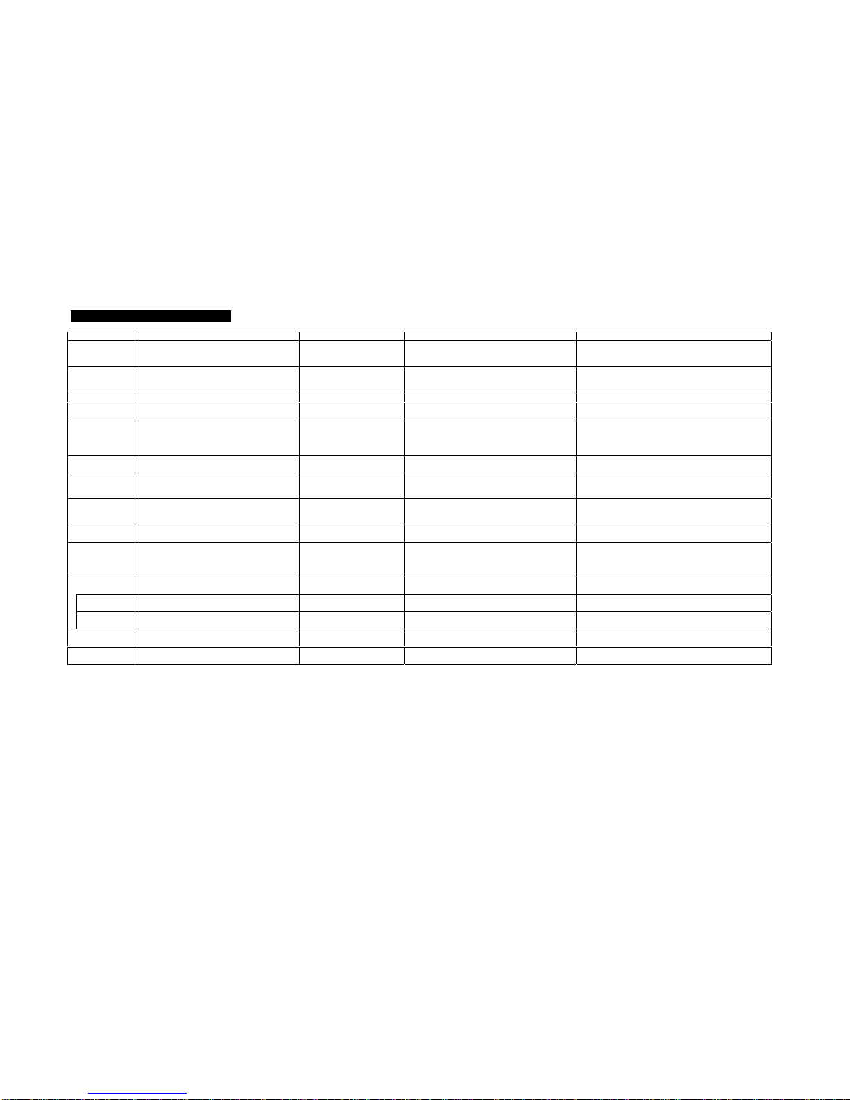
3. ERROR MESSAGE (E-X or F-X)
Error Code Main Failure Causes Related Part Main Checking Items Other Checking Items
E-0 The internal temperature of the heater has
been overheated. High Limit Switch To be continuity at room temperature. Circulation Fan Cover, Circulation Fan, pluggedAir
Duct, stained Louvers, Circulation Fan Motor with lack
of rotation, Fuel Pump with an excessive fuel flow.
F-0 Electrical power has been restored after an
extinguishment by electrical power failure. Main Circuit Board Appropriate electric conductance must be
provided when the heater “ON” and “OFF”. Power failure recovered, or cracked solder on the
Main Circuit Board.
E-1 Room Thermistor malfunction. Room Thermistor Resistance should exist (8 – 35 kΩ)
F-1 Burner Thermistor malfunction.
Burner has been lack of preheating. Burner Thermistor Resistance should exist (several MΩto 5 kΩ) Igniter (black coated: 40 – 49 Ωat normal
temperature)
E-2 Re-ignition has been given immediately after
extinguishment.
Primary Flame Rod current was low at
ignition.
Primary Flame Rod
(Ignition safety device) Electric current to be more than 0.3 µAwithin
40 sec. after ignition. Fuel Pump with small fuel flow rate, plugged Fuel
Pump Strainer, Transformer voltage is low, Flame Rod
and/or Burner Ring whitened, leak, plugged Air Filter.
E-5 Tip-over Switch has been actuated. Tip-over Switch Electric conductance to exist at ordinary
operation. Check on the installed conditions (inclination and/or
vibration)
E-6 Primary Flame Rod current has been low in
combustion. Primary Flame Rod
(Incomplete combustion
preventive device)
Current to be more than 2 µA in 2 min. and 30
sec. after ignition. Plugged Fuel Pump Strainer, plugged Air Filter, Flame
Rod and/or Burner Ring whitened, removed /
deformed burner mat.
E-7 Room temperature exceeds 32 °C. Room Thermistor Resistance should exist (8 – 35 kΩ) Installing place of the heater (direct sunbeams,
distance between the rear side of the heater and the
wall)
E-8 Blower Motor malfunction. Hall IC Output voltage to be approx. DC 2.5 V in
operation. Blower Motor
E-9 Secondary Flame Rod current with an
excessive airflow has been low. Secondary Flame Rod
(Ignition safety device) Current to be more than 0.3 µA within 2
minutes and 30 sec. after ignition. Fuel Pump with small fuel flow rate, plugged Fuel
Pump Strainer, Flame Rod and/or Burner Ring
whitened, Blower Motor with abnormal rotation,
plugged Air Filter
-- -- *Care must be taken, since there is
also be a normal condition.
Ventilation
(VENT) Lamp The bottom of the burner has been cooled
off. Burner Thermistor 3 – 20 kΩin 20 min. after ignition. Installing place of the heater (abnormal pass of cold
air)
Fuel Lamp Out of fuel. Float Switch or Fuel Level
Sensor Switch changes over by fuel level. Plugged Fuel Tank Cap and/or Fuel Acceptance
Fitting (fuel condition, configuration)
All Lamps Off Fuse open. Fuse for electric current Receptor to be of AC 230 V. Blower Motor, Circulation Fan Motor, Surge Absorber
on the Main Circuit Board
All Lamps Off
(This is normal) Stand-by position - If display returns back after press of any
buttons (except Operation Switch) -