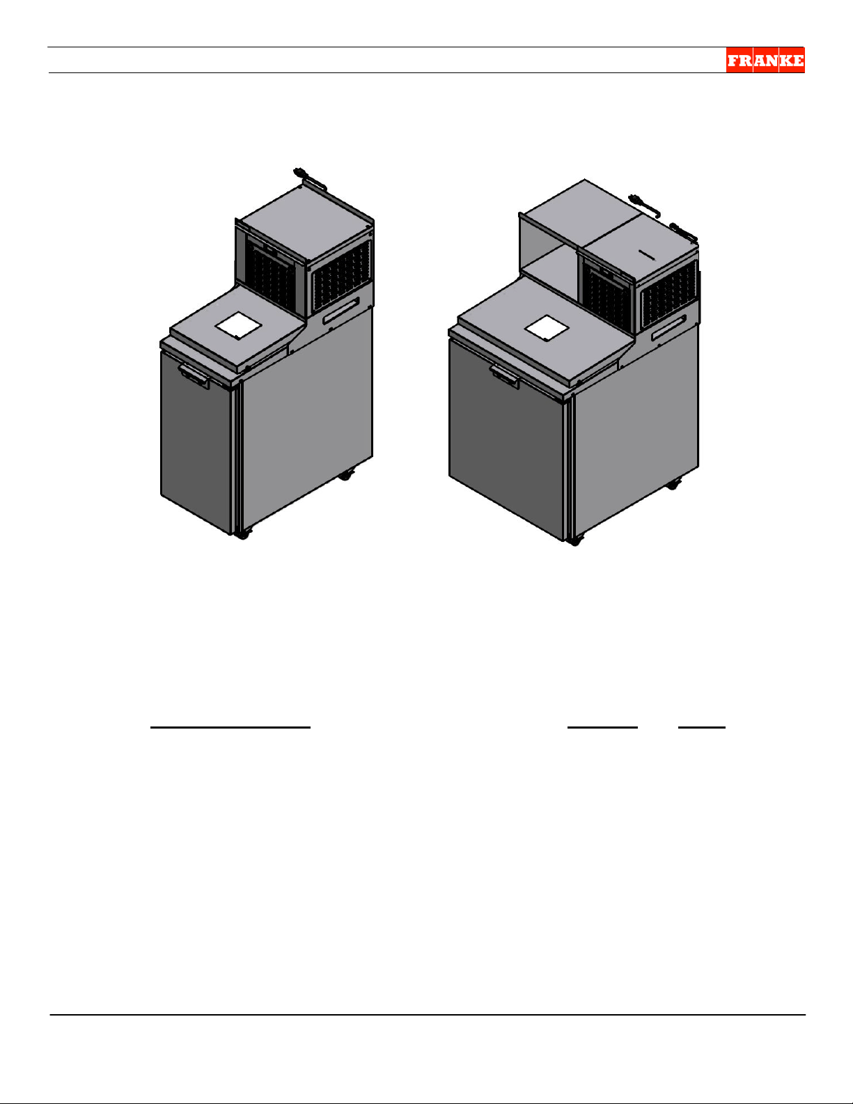
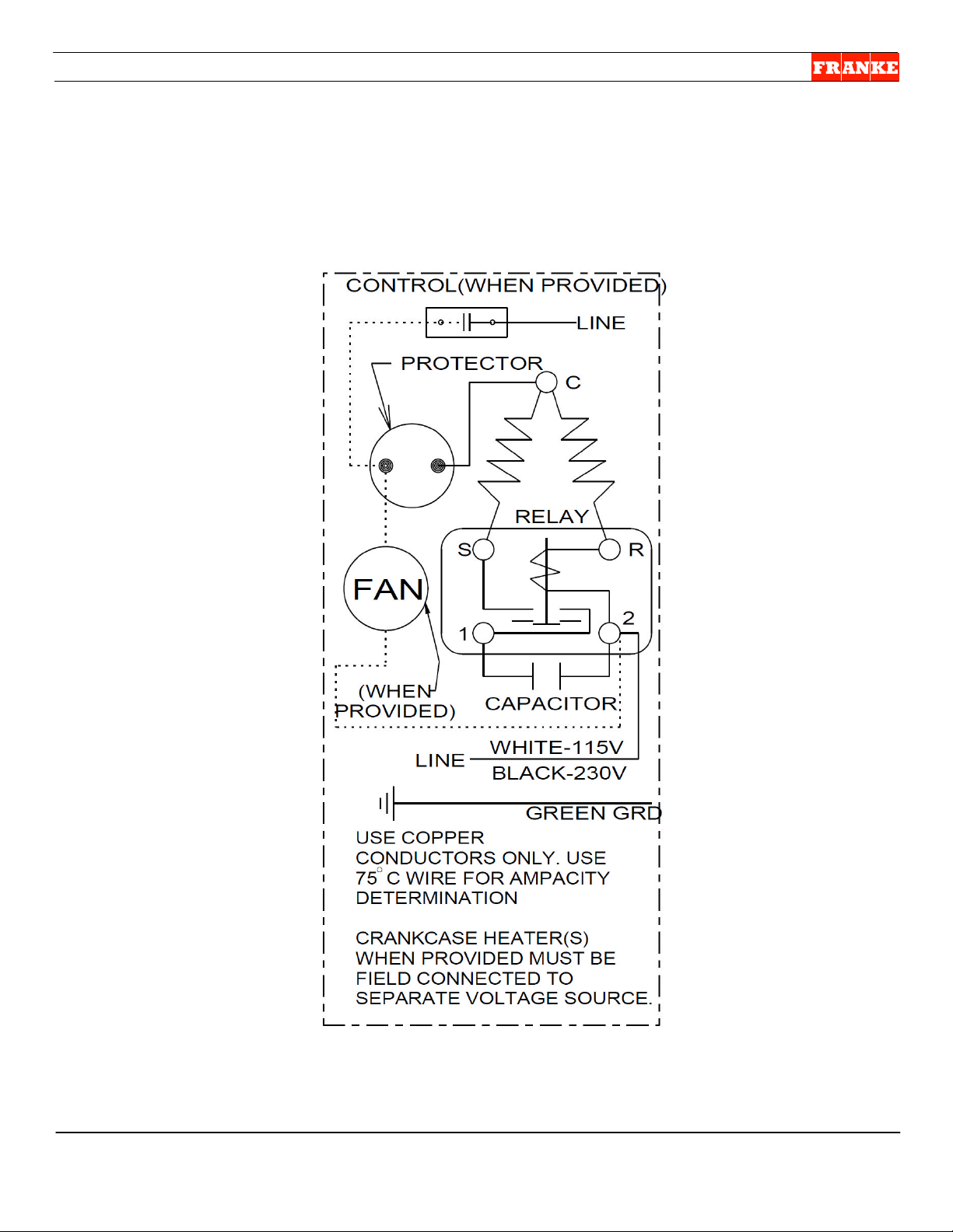
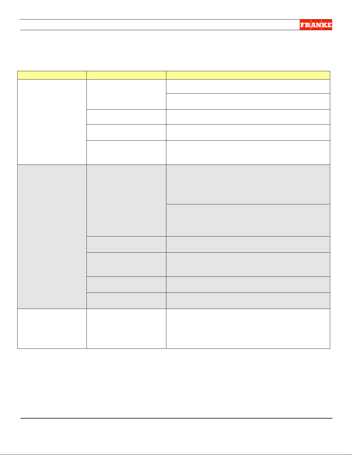
Franke HCMF-18 User manual

HCMF Service Manual
For Technical Support, Call 800-537-2653. Page 1 Doc. No. 19005309 - Copyright 2012 Franke, Inc.
High Capacity Meat Freezers
Model HCMF-18 (18” wide) Model HCMF-30 (30” wide)
Section Contents Section Page
HCMF Model Overview & Specifications 1 2
Control Settings & Operating Parameters 2 4
Electric & Compressor Schematics 3 5
Trouble Shooting Table 4 7
Eliwell Controller Error Codes 5 9
Component Parts List & Diagrams 6 11
Basic Operator Preventive Maintenance 7 13
General Unit Service Instructions & Warnings 8 14
Key Parts Replacement Tips 9 15
Component Adjustments 10 19

HCMF Service Manual
For Technical Support, Call 800-537-2653. Page 2 Doc. No. 19005309 - Copyright 2012 Franke, Inc.
Section 1 – Model Overview & Specifications:
Model HCMF Series – High Capacity Meat Freezers
The HCMF is a compact, custom freezer designed for short-term grill-side storage of frozen
hamburger patties and secondary grilled product, providing quick and easy access at point-of-use.
Designed to be positioned immediately adjacent to the Grill Station, the HCMF is available in two
sizes, 18-inches wide and 30-inches wide, with a front case-loading door and an insulated, automatic
roll-back top lid that provides quick access, with minimum exposure of frozen product.
Unlike previous grill-side freezers (GSF & FRGSF), HCMF Models have a top mounted condenser
package that provides easy access for regular PM and service access from five sides. HCMF Models
are more energy efficient, provide more storage space, cost less to operate and have the following
specifications and utility requirements:
*NOTE: P/N: 18005519 has the condenser mounted top-right. P/N 18005056 has the
condenser factory-mounted top-left.
Key Performance Specifications
Product Model:
HCMF
-
18
HCMF
-
30
Part Number:
1800
5560
1800
5519*
Capacity: Cubic Feet
6.8 13.1
Capacity:
Burgers
3 box 6 boxes
Refrigeration/Type:
Forced air cooling system using R-404A Refrigerant
Agency Listings:
C
UL
US
&
NSF
C
UL
US
&
NSF
Key Dimensions & Weights
Unit Width
:
18” (458 mm) 30.86” (784 mm)
Unit Depth
[front
-
to
-
back]:
37” (940 mm) 37” (940 mm)
Unit Height
54.77” (1391 mm) 54.77” (1391 mm)
Minimum Door Swing
+22” (to depth) +32” (to depth)
Shipping Weight
337 lbs. 427 lbs.
Unit Operating Weight
265 lbs. 365 lbs.
Electric
al
/Utility Requirements
Voltage [VAC]
120 VAC 120 VAC
Phase [PH]
1-phase 1-phase
Cycles [Hz]
60 Hz 60 Hz
Amperage [AMP]
7.3 AMPs 10 AMPs
Watts
840 1200
Power Cord Provided
Yes Yes
Plug Provided
Straight Blade Straight Blade
Installation/Operating Conditions/Requirements
Max. Room Temp.
82F 82F
Max. Room Humidi
ty
60% 60%
Min. Side Clearance
0” (2” recommended) 0” (2” recommended)
Min. Rear Clearance
1” (2” recommended) 1” (2” recommended)

HCMF Service Manual
For Technical Support, Call 800-537-2653. Page 3 Doc. No. 19005309 - Copyright 2012 Franke, Inc.
Model HCMF Key Components
HCMF-30 [18005519 – Condenser-Right] Model Shown
Front Door
(Shown Hinged
Right – Field
Reversible)
Top Roll-Back
Product Access
Door
Temperature
Display/Controller
Disposable Glove
Bracket Mounting
Location
Locking Front
Casters
Grill Tool Shelf
Right Side
Service Access
Panel
Front Vented
Condenser Coil
Access Panel
Power ON/OFF
Switch
(Rear-View)

HCMF Service Manual
For Technical Support, Call 800-537-2653. Page 4 Doc. No. 19005309 - Copyright 2012 Franke, Inc.
Section 2 – Control Settings & Operating Parameters:
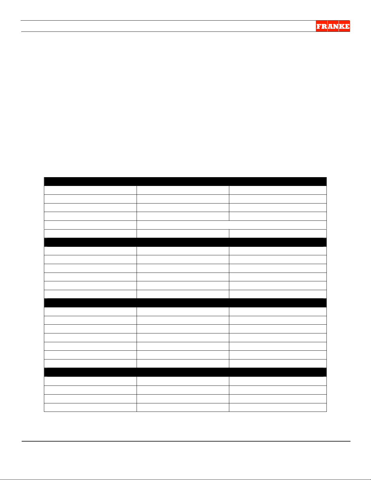
Control Settings & Operating Characteristics (For Troubleshooting)
Danfoss Temperature Controller For More Information
Temperature Range Adjustable
See Section 10 on page 19 to adjust
temperature
Coldest Set Point -30 degrees F
Normal Cut Out (Set Point) - 4 degrees F
Differential 2 degrees F
Normal Cut In - 2 degrees F
Warmest Set Point +30 degrees F
Compressor Protection Fixed
Minimum On Time from Start to Start 2 minutes
Fail Safe Mode (if sensor fails) Fixed
Faulty Probe On Time 4 minutes
Error Off Time 2 minutes
Defrost Settings Fixed
Termination Temperature 60 degrees F
Maximum Time Allowed 60 minutes
Drip Time (heat off) 1 minute
Defrost Based On Compressor On Time Fixed
Time Between Defrosts 3 hours
Fan Settings Fixed
During Defrost Off
Start Delay After Defrost 4 minutes
Fan Duty Cycle – ON 40 seconds
Fan Duty Cycle - OFF 90 seconds
Display Features: Adjustments
Select degrees F or C? No NOTE: Contact Franke for degrees C
Adjust temperature from display? Yes See Section 10 on page 19 to adjust
temperature or initiate manual defrost
Initiate Defrost from display? Yes
Display during Defrost Cycle: dEF
NOTE:
dEF shown for maximum of 30
minutes after defrost.
Normal Operating Pressures Normal Operating Amps
High Side (85 air to condenser) 235 PSIG HCMF-30 8 – 9 Amps (4.8A Defrost)
Low Side (-5 air into coil) 13 PSIG HCMF-18 5 – 6 Amps (3.8 Defrost)
High Pressure Safety Rated Operating Amps
Cut Out Setting 460 PSIG HCMF-30 10 Amps
Differential 30 PSIG HCMF-18 7.3 Amps
Defrost High Limit Safety Operating Voltage
Cut Out Setting 70 degrees F HCMF-30 120V
Differential 15 degrees F HCMF-18 120V
Refrigeration Type
& Quantity
:
HCMF
-
30
HCMF
-
18
R-404A 18 ounces 16 ounces

HCMF Service Manual
For Technical Support, Call 800-537-2653. Page 5 Doc. No. 19005309 - Copyright 2012 Franke, Inc.
Section 3 – Electric & Compressor Schematics:
HCMF-18 & HCMF-30 Wiring Harness
NOTE:
Model HCMF-18 has one fan motor
Model HCMF-30 has two fan motors

HCMF Service Manual
For Technical Support, Call 800-537-2653. Page 6 Doc. No. 19005309 - Copyright 2012 Franke, Inc.
Copeland Compressor Schematic
Model HCMF-18 – Copeland No. M4FL-H038-IAA-121 – Franke P/N: 19004507
Model HCMF-30 – Copeland No. M4FL-H047-IAA-121 – Franke P/N: 19004310

HCMF Service Manual
For Technical Support, Call 800-537-2653. Page 7 Doc. No. 19005309 - Copyright 2012 Franke, Inc.
Section 4 – Trouble Shooting Guide:
The Problem
Possible Cause
What To Check & Do
Main Power not
“ON”
Power not available to
unit?
Breaker OK? Yes = Continue; No = Call electrician
Receptacle OK? Yes = Continue; No = Call
electrician
Power cord OK? Yes = Continue; No = Replace power cord.
Internal wiring OK? Yes = Continue; No = Replace wiring harness.
(Contact Franke Technical Support.)
Power switch not ON?
(Switch located behind
condenser, top-right.)
Check for power at switch. Switch OK? Yes =
Continue; No = Replace Power Switch
(See Tips T-5)
Main Power “ON”
but Freezer does
not run
Compressor thermal
overload tripped?
Unplug Freezer power cord for 1 hour, then retry.
If problem reoccurs, ensure condenser coil is clear
of debris and cleaned, per PMM Page Instructions.
If dirty or obstructed, vacuum or brush off
condenser coil and notify manager.
Test condenser electric components for defects or
failure, including: start-capacitor, start relay,
condenser fan motor & compressor. Replace if
needed. (See Tips T-7)
Power disconnected to
temperature controller
Check input voltage to temperature controller.
Replace wiring harness if damaged.
Temperature controller
disconnected from
condensing unit
Check output voltage at temperature controller.
Replace wiring harness to Condenser, if damaged
Condenser Package is
unplugged inside.
Check Condenser Package plug. (Remove top
access panel.) Plug in if unplugged or loose.
Temperature controller
is defective
Replace defective controller. (See Tips T-2)
Freezer is turned
ON but is not
cooling &
Temperature
Display reads OFF.
Controller has been
turned OFF
Press the ON/OFF button (top-right) on
Controller/Display to turn ON.

HCMF Service Manual
For Technical Support, Call 800-537-2653. Page 8 Doc. No. 19005309 - Copyright 2012 Franke, Inc.
Section 4 – Trouble Shooting Guide CONTINUED:
The Problem
Possible Cause
What To Check & Do
Temperature
Display Reads
Temperature But
Freezer Does Not
Cool To 0° F
Set point too high Adjust thermostat setting. (See Adjustment A2)
Door and/or Rolling Lid
leaking cold air
Inspect door and lid gaskets for damage. If needed
replace. (See Tips T-1)
Evaporator fan not
functioning
Check fan for blockage. Clear blockage if found.
Check motor and replace if not running properly.
(See Tips T-10)
NOTE: It is normal for the evaporator fan(s) to
cycle on-and-off when the compressor isn’t
running.
Evaporator coil blocked
with ice
Check temperature controller circuit for defrost
heater. Does relay close when manual defrost is
initiated? If not, replace temperature controller.
(See Tips T-2)
Check high temperature cutoff switch for proper
function. If needed, replace.
Check the defrost heater integrity. If needed,
replace defrost heater. (See Tips T-9)
Refrigerant charge is
not correct or system
has a leak.
Inspect service valves, lines, joints and
components for signs of leaks, kinks or restrictions.
Check system pressure and check for leaks. If
leak is found, repair leak.
Condensing unit is not
starting properly or is
tripping on overload.
Ensure condenser coil is clean, unobstructed and
being cleaned every three months (or more
frequently, if needed) per HCMF PMM Page
instructions. If dirty or obstructed, vacuum or brush
out condenser coil and notify unit manager.
Check condenser electrical components for defects
(start-capacitor, start-relay, condenser fan motor,
compressor, etc.) Replace if needed. (See Tips)

HCMF Service Manual
For Technical Support, Call 800-537-2653. Page 9 Doc. No. 19005309 - Copyright 2012 Franke, Inc.
Section 5 – Eliwell Controller Error Codes:
The Eliwell Controller provides error code messages on the temperature display when the HCMF
freezer is not performing as required. Alarms are indicted by the error code and an alarm icon
which appears on the controller display.
The Problem
Possible Cause
What To Check & D
o
Error Code E1
Displayed – Probe
1 Faulty
Measured values outside
operating range
Probe faulty, short
circuited or open
Check probe for damage
Check probe wiring for damage. If faulty:
Replace temperature probe. (See Tips T-3)
Error Code
E2
Displayed – Probe
2 Faulty
Measured values outside
operating range
Probe faulty, short
circuited or open
Check probe for damage
Check probe wiring for damage. If faulty:
Replace defrost probe. (See Tips T-4)
Error Code AH1
Displayed – Alarm
for HIGH probe
temperature
Value measured by probe
greater than HAL (50F)
after (tAL) factory set
time???
Wait for value read by probe (Pb1) to return
below HAL
Error Code
AL1
Displayed – Alarm
for LOW probe
temperature
Value measured by probe
greater than LAL (-50F)
after (tAL) factory set
time???
Wait for value read by probe (Pb1) to return
below LAL
This is typically a probe failure. If faulty,
replace temperature probe. (See Tips T-3)

HCMF Service Manual
For Technical Support, Call 800-537-2653. Page 10 Doc. No. 19005309 - Copyright 2012 Franke, Inc.
Section 6 – Key Parts & Exploded Parts Diagrams: (Model HCMF-30 Shown)
Key No.
Part Description
HCMF
-
18 P/N
HCMF
-
30 P/N
1
Door Gasket (Front) 19004385 19004309
2
Lid Gasket (Roll-back Top) 19004631 19004449
3
Condensing Unit (Copeland) 19004507 19004310
4
Eliwell Display/Controller 18005958 18005958
5
Cord Set (5-15P) 19000282 19000282
6
Power ON/OFF Switch (Carling) 3126151 3126151
7
Casters, Swivel - Locking 19000817 19000817

HCMF Service Manual
For Technical Support, Call 800-537-2653. Page 11 Doc. No. 19005309 - Copyright 2012 Franke, Inc.
Section 6 – Key Parts & Exploded Parts Diagrams: Evaporator Coil
Key No.
Part Description
HCMF
-
18 P/N
:
HCMF
-
30 P/N
:
1
Defrost Heating Element
19004386 19004308
2
Evaporator Coil
19002059 19002060
3
Thermostatic Expansion Valve
19001190 19001190
4
Evaporator Fan
Motor
19000455 19000455 (2 ea.)
5
High Limit Switch
19004832 19004832
6
Air Temperature Sensor
(grey)
19004769 19004769
7
Defrost Coil Sensor
(yellow)
19004832 19004832

HCMF Service Manual
For Technical Support, Call 800-537-2653. Page 12 Doc. No. 19005309 - Copyright 2012 Franke, Inc.
Section 6 – Key Parts & Exploded Parts Diagrams: Condenser Package*
* For other sub-components contact Franke Technical Support.
Key No.
Part Description
*
HCMF
-
18 P/N
HCMF
-
30 P/N
1
Compressor Only 19005288 19005289
2
Start Relay 19005290 19005291
3
Start Capacitor 19005292 19005292
4
Condenser Fan Motor 19005293 19005293
5
Condenser Unit/Package 19004507 19004310

HCMF Service Manual
For Technical Support, Call 800-537-2653. Page 13 Doc. No. 19005309 - Copyright 2012 Franke, Inc.
Section 7 – Operator Preventive Maintenance:
NOTE: Before attempting service, failure diagnosis or component
repairs, verify basic operator maintenance has been done.
PROBLEM: Freezer is running but will not reach 0F [-18C] or
lower. High temperatures caused by a dirty condenser coil,
blocking the front or side louvered panels or direct contact with
the Grill Station may cause the freezer to function improperly, not
maintain temperature or cease operating.
1) FIRST- Perform a Manual Defrost: Push and HOLD (for
five seconds) the lower button to the left of temperature
display. Display will read: dEF.
2) Open the front compartment door and verify that freezer has
been defrosted. If significant ice buildup is still present, turn
OFF rear power switch, open the freezer compartment door
and allow the ice to melt.
3) Check to see if freezer is overloaded or if plastic carton
liners are obstructing evaporator fan openings.
4) Check freezer door gasket for damage. If damage is found,
replace the door gasket.
5) Check rear and side clearance around unit. To operate
efficiently, the following clearances are recommended:
Model
Min.
Side Clearance
Min.
Rear Clearance
HCMF-18 0” (2” recommended) 1” (2” recommended)
HCMF-30 0” (2” recommended) 1” (2” recommended)
6) Pull off front louvered access panel. Inspect the condenser
coil to ensure it is clean and free of dust and debris. If it is
dirty, clean it with a soft bristle brush or portable vacuum.
7) Test unit for operation within the 0to -10F [-18 to -23C]
normal operating temperature range.
8) If these steps correct problem, notify unit manager of
problems noted with crew cleaning, operator preventive
maintenance or location of unit. If problem persists, see
Troubleshooting Guide.
[Photo 1]
If freezer needs defrosting, push
and hold lower button for five
seconds. Display will read: dEF.
[Photo 2]
To inspect condenser coil, pull off
the front access panel. It has right
& left magnetic catches.
[Photo 3]
If condenser coil is dirty, clean with
soft brush or portable vacuum.

HCMF Service Manual
For Technical Support, Call 800-537-2653. Page 14 Doc. No. 19005309 - Copyright 2012 Franke, Inc.
Section 8 – General Unit Service Instructions & Warnings:
1) Technicians should be authorized to work on Franke
Equipment and be EPA Certified and qualified to diagnose
and repair refrigeration equipment.
2) The Franke High Capacity Meat Freezer comes in two sizes,
the compact HCMF-18 model and larger HCMF-30 model.
3) Both models operate on 120-volt power and are provided with
a grounded (5-15P) plug and 8’ power cord.
4) The HCMF-30 refrigeration system is charged with 18 ounces
(539 g) of ozone-safe R404A refrigerant. The HCMF-18 is
charged with 16 ounces (311 g) See unit Data Plate and use
in-line site glass provided, when filling.
5) Only use R404A refrigerant when recharging this unit.
6) Always verify proper unit cleaning before replacing or
repairing components. [See Section 6]
Suggested [On-Truck] Repair Parts:
We suggest the following to ensure a first-trip fix of a HCMF:
HCMF-18 HCMF-30 Description Qty.
19004385 19004309 Front Door Gasket 1 ea.
19004631 19004449 Top Rolling Door Gasket 1 ea.
19001991 19001991 Top Rolling Door Rollers 4 ea.
18005958 18005958 Display/Controller- Eliwell 1 ea.
19004386 19004308 Defrost Heater (Evaporator) 1 ea.
19004769 19004769 Sensor, Air Temp. (Gray) 1 ea.
19004832 19004832 Sensor, Coil Temp (Yellow) 1 ea.
19000817 19000817 Swivel Caster w/Brake 4 ea.
19005293 19005293 Condenser Fan Motor 1 ea.
19000454 19000454 Evaporator Fan Motor 2 ea.
19005292 19005292 Start Capacitor 1 ea.
19005290 19005291 Start Relay 1 ea.
19001190 19001190 Thermostatic Expansion Valve 1 ea.
19004507 19004310 Condensing Unit 1 ea.
19005288 19005289 Compressor ONLY 1 ea.
3126151 3126151 Power ON/OFF Switch 1 ea.
19000282 19000282 Power Cord (8’) & Plug 1 ea.
19004832 19004832 High Limit Switch 1 ea.
[Model & Serial Number]
The HCFM Unit Serial Number is
located below the Model Number &
Data sticker, which is on the back
of unit.
Tools Required:
[For Mechanical Systems Repair]
3/8” screwdriver
¼” screwdriver
1/16” “mini” screwdriver
1/8” Allen/hex wrench
3/16” Allen/hex wrench
5/32” Allen/hex wrench
5 mm Allen/hex wrench
13 mm Allen/hex wrench
7/16” box/socket wrench
Razor knife
Needle nose pliers
Small wire cutters
Rubber mallet
Plastic Wire Ties
WARNING:
Unplug unit from its120-volt power source whenever
servicing electrical components or removing the rear or
side service access panels. Failure to unplug unit may
result in electric shock, burns or death.

HCMF Service Manual
For Technical Support, Call 800-537-2653. Page 15 Doc. No. 19005309 - Copyright 2012 Franke, Inc.
Section 9 – Key Parts Replacement Tips:
This HCMF Condensed Service Manual assumes you are familiar with basic refrigeration repair and
previous Franke Grill-Side Freezers, including GSF and FRGSF Models. See Tips tables that follow
for some HCMF-specific service tips.
Replacement Part Covered
Page
Replacement Part Covered
Page
T
-
1
Door Gasket Replacement 15
T
-
6
Condenser Package Replacement 17
T
-
2
Eliwell Controller Replacement 15
T
-
7
Start Relay & Capacitor Replace. 17
T
-
3
Temperature Sensor Replacement 16
T
-
8
Condenser Fan Replacement 17
T
-
4
Defrost Sensor Replacement 16
T
-
9
Defrost Heater Replacement 18
T
-
5
Power ON/OFF Switch Replace 16
T
-
10
Evaporator Fan Motor Replace. 18
For additional information refer to GSF or FRGSF Service Manuals, or contact Franke
Technical Support at 800 537-2653.
T
-
1
Front Door
or Top
Gasket Replacement
Tips
:
P/N: 19001773 or 19001986
1. Remove the door to replace the gasket.
2. NOTE: Plastic extrusion can be easily damaged. Using a razor
knife to separate the old gasket from its retaining tailpiece.
3. Remove the separated tailpiece from the slot by pulling toward
each corner, using a small needle nose plier.
4. Insert new gasket tailpiece into the gasket-mounting slot. Align the
corners and start at the top of the door. Continue around the door.
5. Tip: Place door on a cushioned surface and carefully hammer the
new gasket tailpiece into the slot
T
-
2
Temperature Display/Controller Replacement Tips:
P/N: 18005969
1. Access controller through top panel. You can access and remove
connections without removing the controller.
2. Use small screwdriver to release/secure control and sensor wires:
Harness wires into terminals marked: 1-6
Yellow Coil Sensor wires into terminals: 8 &10
Grey Air Sensor wires into terminals: 9 &10
3. Test Controller - Initiate manual defrost by pushing the lower –left
button for 7-10 seconds, until display reads: dEF.Compressor will
shut off and the evaporator heater coil will come on. At the end of
manual defrost cycle, heater will shut off, compressor will start and
the display will show actual compartment temperature. An electric schematic is on top
of Controller.

HCMF Service Manual
For Technical Support, Call 800-537-2653. Page 16 Doc. No. 19005309 - Copyright 2012 Franke, Inc.
T
-
3
Temperature Sensor/Cable Replacement Tips:
P/N: 19004769
1. Follow grey sensor cable up to compartment penetration/chase
leading up to Evaporator. Cut any wire ties that bind sensor cable
to other harness wires.
2. Obtain new Air Temperature Sensor & Cable [P/N: 19004769],
remove any protective packaging and uncoil the cable.
3. From inside freezer compartment – use electric tape to secure
connector-end of new sensor cable to the old sensor.
4. Through the right access panel – carefully pull the old sensor cable
down through electric chase until new sensor cable connector will
reach the Controller.
5. Remove tape and discard old sensor & cable.
6. Use plastic tie to secure sensor cable to top of wire chase.
NOTE: Ensure sensor doesn’t touch evaporator coils.
Remove drip pan cover
mounting screws, maneuver
cover over heater coil and out.
T
-
4
Defrost Sensor/Cable Replacement Tips:
P/N: 19004832
1. From inside freezer compartment – gently pull defrost coil sensor
out of top of Evaporator Coil. NOTE: Be careful not to bend delicate
coil fins.
2. Follow yellow sensor cable up to compartment penetration/chase
leading up to Evaporator. Cut any wire ties that bind sensor cable
to harness wires.
3. Obtain new Air Temperature Sensor & Cable [P/N: 19004832],
remove any protective packaging and uncoil the cable.
4. From inside freezer compartment – use electric tape to secure
connector-end of new sensor cable to the old sensor.
5. Through the right access panel – carefully pull the old sensor cable
down through electric chase until new sensor cable connector will
reach the Controller.
T-5 Power ON/OFF Switch Replacement Tips: P/N: 3126151
1. To access power switch, remove the six screws that secure to top
Grill Tool Shelf to condenser enclosure. Lift off.
2. Remove the terminal connectors to the three switch terminals
marked: 1-2-3.
3. Remove the two screws from the switch mounting plate that
doubles as a protective bezel.
4. Position new switch through bezel and attached to condenser
housing frame.
5. Attach wires marked 1-2-3 to corresponding switch terminals.
6. Replace Tool Shelf, test the new switch and unit operation.

HCMF Service Manual
For Technical Support, Call 800-537-2653. Page 17 Doc. No. 19005309 - Copyright 2012 Franke, Inc.
T
-
6
Condenser Package Replacement Tips:
P/N: 19004507 or 19004310
1. Rear, left side and right side access panels can be removed to
provide easy access to the condenser package.
2. Slit insulation on refrigeration lines 6” [15-18 cm] above enclosure
bottom. Push back or remove enough insulation to expose sweat
joints. Sweat those joints to separate compressor from evaporator.
3. IMPORTANT: Recover any residual refrigerant and ensure line
pressure is equalized to zero, before opening the refrigeration
system.
4. NOTE: When resealing the system, use a continuous Nitrogen
charge to assure no contaminants enter the system, especially
when brazing.
T
-
7
Start Relay & Start Capacitor Replacement
See Part No. Guide below
1. Access relay and capacitor through right side access panel.
2. The start relay and capacitor are mounted in a plastic box just right
of the compressor. (See page 6 for relay terminal connections.)
3. WARNING - Use caution when working around capacitor. There is
a danger of electrical shock, which can cause injury or even death!
4. Top of box opens to provide access to both components.
Part No. Guide Model HCMF-18 Model HCMF-30
Start Relay: 19005290 19005291
Start Capacitor: 19005292 19005292
T
-
8 Condenser Fan Motor Replace
ment
P/N: 19005293
1. Disconnect fan motor wires from start relay terminals.
2. Remove four screws securing wire condenser fan guard to
condenser.
3. Slowly move fan assembly between rear of compressor and
condenser coil housing. NOTE: It is a tight fit; remove the Grill Tool
Shelf to gain access from above.
4. Separate condenser motor from the wire fan guard & a 1/8” Allen
Wrench to loosen setscrew and remove motor fan blade.
5. Take new motor [P/N 19005293] and mount to wire fan guard.
6. IMPORTANT: When reinstalling fan, make sure fan blades are
facing the proper direction.
7. NOTE: Make sure motor wires are clear of refrigeration lines. Use
wire ties as needed.

HCMF Service Manual
For Technical Support, Call 800-537-2653. Page 18 Doc. No. 19005309 - Copyright 2012 Franke, Inc.
T
-
9 Defrost Heater Replacement
P/N: 19004386 or 19004308
1. The defrost heater is mounted below the evaporator coil on the
sloped condensate collection pan. One loop is pressed into the
bottom fins of the evaporator coil
2. Gently pull heater loop free of evaporator coil. IMPORTANT:
Use caution to avoid damaging coil fins.
3. Disconnect heater leads from the high-limit and harness,
located above the evaporator coil.
4. DANGER - The coil test procedure requires the unit to be
operated with a service access panel open and meter checking
of HOT/live electrical wiring. This test should only be done by a
qualified service technician, taking safety precautions.
5. On HCMF-18 Model the heater AMP draw should be about 3.8
(450W @120V); on HCMF-30 Model heater AMP draw should
be about 4.8 (575W @120V).
T
-
10 Evaporator Fan Motor Replacement
P/N: 19000455
1. When re-attaching the fan blade, gently press it on the motor
shaft. IMPORTANT: Make sure the fan blade is installed
correctly so that it will blow air UP.
2. Secure the motor/harness to the motor strap using a wire tie.
NOTE: Make sure wire won’t interfere with fan blade(s).
3. IMPORTANT: Before powering up unit, verify that evaporator
fan blade(s) turn freely.
4. To TEST, plug in unit to a 120-volt power source. NOTE: There
is a four (4) minute delay after compressor starts and the
evaporator must get cold (10F) before fan(s) come on.

HCMF Service Manual
For Technical Support, Call 800-537-2653. Page 19 Doc. No. 19005309 - Copyright 2012 Franke, Inc.
Section 10 – Component Adjustments
The HCMF is designed with some adjustable components including removable mirror-image door
hinges to change the swing, plus a controller that can change the target temperature set point.
A
-
1
To
Change
Door
Swing (HCMF ships Hinged
-
Left)
Remove upper hinge, left off door then
remove the bottom hinge.
Mount lower hinge, place door on
bottom hinge pin &secure top hinge.
1. Using a 10 mm wrench or socket to remove the two upper
hinge bracket-mounting bolts, while supporting the weight of
the door. [Tip: If a second person is available, have them
support the weight of the freezer door.]
2. Remove upper hinge bracket from the door bushing.
3. Lift the door up and off the lower hinge pin.
4. Remove the two M6 hex bolts from lower hinge bracket.
5. Locate the mirror image bracket mounting holes on the right
side of the freezer cabinet frame. Remove fill plugs with sharp
flat blade screwdriver. [Save them.]
6. Take the upper hinge-mounting bracket and reinstall it in the
lower hinge position with the hinge pin up, using the same
two mounting bolts.
7. Rotate the Freezer Door 180 degrees and place what was the
upper hinge bushing on the lower hinge mounting bracket pin.
8. Position the remaining [former lower] hinge mounting bracket
with the pin in the [now] upper door hinge bushing and secure
that bracket with the two remaining M6 Hex mounting bolts.
9. Take the hole fill plugs and press them back into the left side
bracket mounting holes.
A
-
2
To
Change Set Temperatur
e
1. Push ‘SET’ button to display: SEt then press it again to display
the set point temperature, which is factory set at -5to -7F.
2. Push the up-arrow button (upper-left) to raise target
temperature or the down-arrow button (lower-left) to lower set
point.
3. The current compartment temperature will automatically
reappear. (If the target temperature was reduced, the
compressor should come on to lower the compartment
temperature.)
(See Section 7 to initiate a Manual Defrost Cycle)
Other manuals for HCMF-18
1
This manual suits for next models
1
Table of contents
Other Franke Freezer manuals

Franke
Franke HCMF-30P User manual

Franke
Franke FSDF 300 NF XS E User manual

Franke
Franke GSFP 450 R290 User manual

Franke
Franke SU03 User manual

Franke
Franke HCMF-18 User manual

Franke
Franke 2DCF-30 User manual

Franke
Franke HCWF-P User manual

Franke
Franke 2DCV-30 User manual

Franke
Franke HCWF-28 User manual

Franke
Franke 2DCV-30 User manual