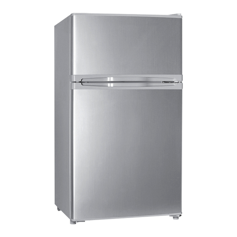
Franke HCWF-P User manual

MODEL: HCWF-P
PART NUMBER: 18014457
High Capacity Wall Freezer
OPERATION & INSTALLATION MANUAL
HIGH CAPACITY WALL FREEZER

219011713 - Rev. A - November 29, 2018
EXPLANATION OF SAFETY AND NOTICE SYMBOLS
DANGER DANGER indicates a hazardous situation which, if not avoided, WILL result in death or serious injury.
WARNING WARNING indicates a hazardous situation which, if not avoided, COULD result in death or serious injury.
CAUTION CAUTION indicates a hazardous situation which, if not avoided, could result in minor or moderate injury.
NOTICE
NOTICE is used to address practices not related to physical injury.
READ AND SAVE THESE INSTRUCTIONS
DANGER
Energized electrical circuits present a life-
threatening hazard of electric shock, explosion,
or arc flash.
-NEVER hose down unit or clean with water jet.
-ALWAYS disconnect unit from power IMMEDIATELY
if bare wires or other electrical conductors are
exposed.
-ALWAYS ensure all electrical circuits are
disconnected and discharged, with an
appropriately rated voltage detecting device,
before performing service, maintenance, or
installation work.
-ALWAYS follow all national and local standards,
laws, and codes, as well as all applicable safe
electrical work practices.
Failure to follow these safety instructions WILL result
in death or serious injury.
Refrigeration systems that use R-290 (Propane)
present a life-threatening hazard of fire or
explosion. All refrigeration systems present a
hazard of flash freezing and oxygen displacement.
-ONLY defrost unit naturally to avoid puncture or
damage to the refrigeration circuit.
-ALWAYS perform repairs on the unit in a well
ventilated area, away from any source of ignition.
-ALL service work MUST be performed ONLY by
factory-authorized service personnel following
all national, local, or other applicable refrigerant
safe handling work practices, standards, laws, and
codes.
-ONLY use original equipment manufacturer
(OEM) components designed for use in R-290
refrigeration systems when servicing, to minimize
the risk of ignition from incorrect parts or improper
service.
-ALWAYS use caution when handling or moving
refrigerated equipment to avoid damage to the
refrigeration tubing so as to minimize the risk of
leaks.
-ALWAYS read the unit’s operation and service
manuals completely before performing service
work.
-ALWAYS use caution when handling refrigeration
discharge lines because they are hot and can burn.
-ALWAYS wear appropriate personal protective
equipment (PPE) when servicing equipment.
Failure to follow these safety instructions WILL result
in death or serious injury.
WARNING
Unauthorized modifications or repairs pose a
hazard in the form of an improperly functioning
unit.
-ONLY for commercial use.
- NEVER make ANY modifications to the unit that are
not authorized by documentation provided by Franke.
-NEVER remove any labels from the unit.
-ALWAYS replace ANY labels that have been
removed or damaged IMMEDIATELY.
-ONLY use original equipment manufacturer (OEM)
parts when service, maintenance, or installation
work is performed.
IMPORTANT SAFETY INFORMATION
19011713 - Rev. A - November 29, 20183
-NEVER operate with factory installed parts or
components removed.
-NEVER use for other than intended use.
Failure to follow these safety instructions COULD
result in death or serious injury.
These instructions are intended for qualified
persons ONLY. Use by others creates an unsafe
condition.
-ONLY persons who are certified technicians or
trades persons with the requisite knowledge, skills,
ability, and training, MUST perform service or
installation work.
-ALWAYS keep out of the reach of children.
-ONLY allow access to unit by trained personnel
who have read this manual.
Failure to follow these safety instructions COULD
result in death or serious injury, as well as property
damage or void of warranty.
CAUTION
Lifting and transporting heavy objects poses a
hazard of injury.
-NEVER lift or move equipment without proper tools
or assistance.
Failure to follow these safety instructions COULD
result in minor to moderate injury.
Steel surfaces may have sharp edges which pose
a hazard of injury
-ALWAYS wear appropriate personal protective
equipment (PPE) when moving or handling
equipment.
Failure to follow these safety instructions COULD
result in minor to moderate injury.
NOTICE
NEVER use inappropriate tools, processes, or
procedures. Damage to components of unit can
occur.
-Follow these instructions EXACTLY to avoid
property damage or void of warranty.
NEVER discard any loose parts received with
unit. They may be required for proper and safe
installation and operation.
IMPORTANT SAFETY INFORMATION

419011713 - Rev. A - November 29, 2018
TABLE OF CONTENTS
Important Safety Information................................................................................. 2
Key Components ...................................................................................................... 5
Overview .........................................................................................................................5
Installation ................................................................................................................ 6
Installing the HCWF-P......................................................................................................6
Reversing the Freezer Door ...........................................................................................10
Controls & Settings ................................................................................................12
Power ON/OFF Switch ..................................................................................................12
Factory Preset Temperature and Adjustable Range.......................................................12
Unit Temperature Adjustment .......................................................................................12
Manual Defrost..............................................................................................................13
Operation ................................................................................................................13
Shelf Positioning............................................................................................................13
Product Loading Guidelines...........................................................................................15
Troubleshooting .....................................................................................................16
Warranty..................................................................................................................17
Notes .......................................................................................................................18

19011713 - Rev. A - November 29, 20185
KEY COMPONENTS
Overview
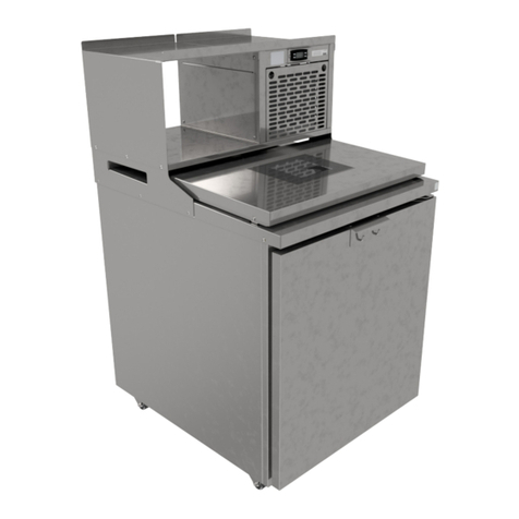
The High Capacity Wall Freezer (HCWF-P) is a
compact freezer designed for short-term storage
of frozen product, providing quick access near the
point-of-use. Designed to be wall-mounted near the
Fryer Station to save space, the HCWF-P is currently
available in a 28" wide, single door model.
The freezer compartment has two wireform shelves
that slide into right and left shelf supports that
provide six shelf height positions. The HCWF-P also
features a reversible freezer door, easy-to-clean
stainless steel surfaces throughout, and a digital
temperature controller for monitoring the current
temperature of the unit.
Fig. 1
1
2
3
4
5
6
ITEM PART NAME QTY
1 Power ON/OFF Switch 1
2 Adjustable Wire Shelves 2
3 Digital Temperature Controller 1
4 Condenser Coil Access Panel 1
5 Freezer Door (Hinged Right) 1
6 Freezer Door Gasket 1
Table 1

619011713 - Rev. A - November 29, 2018
INSTALLATION
Installing the HCWF-P
NOTICE
IMPORTANT INSTALLATION INFORMATION
Remove all tape, protective film, and foam blocking from the unit before installation. Wash, rinse, and sanitize
wire shelves before use.
High Capacity Wall Freezers (HCWF-P) are designed for wall installation to either left or right side of fry station.
Unit must be installed within 10' of an appropriately rated electrical receptacle, per the specifications listed on
the unit’s data label.
Mounting wall MUST be capable of supporting at least 100 lbs (45 kg) of weight per linear foot. If drywall
construction is evident at installation location, wall MUST be reinforced with minimum ½" thick plywood. Securely
anchor plywood to a minimum of two (2) wall studs.
STEP 1
Locate steel offset mounting strip supplied with unit.
Mounting strip is designed for engage full width of
HCWF-P top-rear flange (Fig. 2).
Fig. 2
OFFSET MOUNTING STRIP
STEP 2
Measuring up 80" from the finished kitchen floor,
locate center point of intended freezer mounting
position on the wall (Fig. 3).
NOTICE
IMPORTANT INSTALLATION INFORMATION
If installing the HCWF-P above a 2-Drawer Refrigerator,
Combo Cooler/Freezer, or Convertible Cooler/
Freezer, measure 77" above finished kitchen floor.
80" HEIGHT ABOVE FLOOR
Fig. 3

19011713 - Rev. A - November 29, 20187
INSTALLATION
STEP 3
Place bottom of mounting strip against kitchen wall at
measured height and offset from center mark. Level
mounting strip and mark location of screw holes pre-
drilled into strip (Fig. 4). Remove strip and drill pilot
holes into marked locations.
Fig. 4
STEP 4
Secure mounting strip to wall using hardware
appropriately rated to wall materials and weight-
bearing requirements noted on page 4 (Fig. 5).
Fig. 5
OFFSET MOUNTING STRIP WALL MOUNTING BOLTS
STEP 5
CAUTION
LIFTING HAZARD
Use appropriate help, tools, and techniques when
lifting or moving heavy objects.
With appropriate assistance, lift HCWF-P to a height
that clears previously installed mounting strip. Lower
freezer until top-rear flange of freezer rests completely
on mounting strip. Continue to support weight of
freezer (Fig. 6).
Fig. 6
STEP 6
While continuing to support freezer, install supplied
L-shaped bracket against wall and flush to freezer
bottom. Fasten bracket with provided mounting
screws (Fig. 7).
Fig. 7
L-SHAPED BRACKET WALL MOUNTING BOLTS

819011713 - Rev. A - November 29, 2018
INSTALLATION
STEP 7
Install three (3) appropriately-rated mounting
screws, based on wall materials and weight-bearing
requirements noted on page 4, through HCWF-P top
brace (Fig. 8). Drill pilot holes as needed.
Fig. 8
STEP 8
Span strut channel across two (2) ceiling trusses,
above drop ceiling (Fig. 9).
Fig. 9
STRUT CHANNEL
STEP 9
Screw all-thread support rod into nutsert attached
at top of freezer compartment, behind evaporator
housing (Fig. 10).
Fig. 10
STEP 10
Secure other end of all-thread rod to strut channel,
using supplied hardware (Fig. 11).
Fig. 11

19011713 - Rev. A - November 29, 20189
INSTALLATION
S T E P 11
Cover exposed all-thread rod using provided length of
split plastic tubing. Trim tubing as needed (Fig. 12).
Fig. 12
STEP 12
Uncoil power cord from within evaporator housing.
Plug unit into appropriately-rated electrical receptacle,
per specifications noted on unit data label (Fig. 13).
Restrain excess cord length using plastic wire ties.
Fig. 13
STEP 13
Wash, rinse, and sanitize wire shelves as noted on page 4. Clean all interior an exterior surfaces of unit with a store
approved cleaning and sanitizing solutions and clean, sanitized towels. Place clean, dry shelves at desired heights
within freezer compartment (Fig. 14).
Fig. 14

1019011713 - Rev. A - November 29, 2018
INSTALLATION
Reversing the Freezer Door
CAUTION
RISK OF PERSONAL INJURY
Use caution when removing door to avoid dropping heavy components onto feet.
The HCWF-P freezer door is field-reversible and designed for right- or left-handed swing. Use the following
procedure to reverse the door if required due to installation location.
STEP 1
Hold freezer door open. Remove two (2) screws
fastening bottom-right hinge to front of unit (Fig. 15).
Reinstall screws into empty holes.
Fig. 15
STEP 2
Remove freezer door from top-right hinge (Fig. 16).
Set door aside for later re-installation.
Fig. 16
STEP 3
Remove two (2) screws fastening top-right hinge to
front of unit (Fig. 17). Reinstall screws into empty holes.
Fig. 17
STEP 4
Turn top-right hinge upside-down and install to bottom-
left position using pre-installed screws (Fig. 18).
Fig. 18

19011713 - Rev. A - November 29, 201811
INSTALLATION
STEP 5
Turn freezer door upside-down. Place door onto bottom-left hinge (Fig. 19).
Fig. 19
STEP 6
Continue to support door. Turn bottom-right hinge upside-down and install to top-left position using pre-installed
screws (Fig. 20). Confirm that door opens smoothly and that door gasket seals fully against freezer compartment.
Fig. 20

1219011713 - Rev. A - November 29, 2018
Power ON/OFF Switch
The High Capacity Wall Freezer (HCWF-P) is provided
with a main power ON/OFF switch, located next to
the temperature controller on the top-left panel at the
front of the unit (Fig. 21).
Fig. 21
POWER ON/OFF SWITCH
Factory Preset Temperature and
Adjustable Range
The temperatures for the High Capacity Wall Freezer
(HCWF-P) are preset at the factory. The preset tem-
peratures are recommended for normal operation. If
needed, the temperatures can be adjusted. The fac-
tory presets and adjustable ranges are shown in the
following table (Table 2).
FACTORY PRESET
TEMPERATURE/CONTROL
SETTING
ADJUSTABLE TEMPERATURE
RANGE
-5° F
(-20.5° C)
0° to -10° F
(-18° to -23° C)
Table 2
Unit Temperature Adjustment
To adjust the temperatures of the unit:
1. Locate the temperature controller on the top-left
panel at the front of the unit (Fig. 22).
Fig. 22
TEMPERATURE CONTROLLER
1. Press SET (Fig. 23).
Fig. 23
2. Press SET again. The current setpoint is displayed.
Press the UP and DOWN arrow buttons to adjust
the temperature setting (Fig. 24).
Fig. 24
CONTROLS & SETTINGS

19011713 - Rev. A - November 29, 201813
CONTROLS & SETTINGS
3. Press the POWER button twice to save the new setting.
The current temperature will be displayed (Fig. 25).
Fig. 25
4. Monitor the unit to verify that it reaches the
desired operating temperature.
Manual Defrost
NOTICE
IMPORTANT OPERATION INFORMATION
The High Capacity Wall Freezer (HCWF-P) is designed
for automatic evaporator coil defrosting. Under normal
operating conditions, NO MANUAL DEFROSTING is
required by the operator.
To initiate a manual defrost:
1. Press and hold down arrow button on display for
five (5) seconds (Fig. 26).
Fig. 26
2. Display will read “dEF” (Fig. 27), compressor
will shut off, and heater will begin melting
excess ice buildup from refrigeration circuit. At
end of manual defrost cycle, compressor will
restart and display will show the current freezer
compartment temperature.
Fig. 27
Shelf Positioning
The High Capacity Wall Freezer (HCWF-P) is designed
to provide three (3) shelves for boxed product,
including:
-Adjustable top and middle wire shelves for
different product and packaging sizes
-A raised, fixed, wireform bottom shelf that
ensures proper air circulation even when freezer
is fully loaded.
To change the top and middle shelf positions:
1. Remove wireform shelves from shelf mounting
brackets, located on either side of freezer
compartment interior (Fig. 28). Wash, rinse, and
sanitize shelves, and allow to dry. Fig. 28
OPERATION

1419011713 - Rev. A - November 29, 2018
OPERATION
2. Remove shoulder bolts securing shelf rails to
interior walls of freezer (Fig. 29). Set rails aside.
Remove pre-installed screws at desired shelf
height and replace with shoulder bolts (Fig. 30).
Install screws into holes at previous shelf location.
Fig. 29
Fig. 30
3. Loosely install shoulder bolts at desired shelf
height (Fig. 31). Rest shelf rail keyholes onto
shoulder bolts, and tighten bolts until fully secure
into freezer walls (Fig. 32).
Fig. 31
Fig. 32
4. Place wire shelves back onto shelf rails. Ensure
shelves are level and that rails are firmly secured
against freezer compartment walls.

19011713 - Rev. A - November 29, 201815
OPERATION
Product Loading Guidelines
NOTICE
RISK OF LOSS OF PRODUCT
Do NOT overload the High Capacity Wall Freezer (HCWF-P). Unit requires proper air circulation to maintain
uniform temperatures. Do NOT let plastic bags, cartons, or other containers to obstruct or block evaporator
intake openings inside of freezer compartment.
Care should be taken when loading frozen product into the High Capacity Wall Freezer (HCWF-P), to ensure that
freezer compartment temperatures remain within safe product storage range.
Fig. 33 indicates the location of the evaporator intake openings. Ensure that the intake openings are NEVER
blocked by packaging or other items.
Fig. 33
EVAPORATOR AIR INTAKE OPENINGS

1619011713 - Rev. A - November 29, 2018
TROUBLESHOOTING
ISSUE POSSIBLE CAUSE REMEDY
Unit does not run.
Rocker switch is in the
OFF position. Toggle the rocker switch to the ON position.
Electronic controller has
been turned off.
Push and hold power button (located in the top-
right corner of controller) for 5-7 seconds.
Circuit breaker has been
tripped.
Check circuit breaker to see if it has tripped.
Reset if necessary.
Unit is running, but does not reach
target operating temperatures.
Store’s ambient
temperature is too high.
Decrease set point temperature of controller
(refer to
Unit Temperature Adjustment
, page 12).
Condenser coil is dirty
or clogged with debris.
Use a soft bristle brush to clean coils (refer to
the store’s
Planned Maintenance Manual
).
Ice buildup on
evaporator coils.
Remove all product, defrost (refer to
Manual
Defrost
, page 13), and allow sufficient time for
unit to reach target operating temperature.
Product is above the target
temperature.
Store’s ambient
temperature is too high.
Decrease set point temperature of controller
(refer to
Unit Temperature Adjustment
, page 12).
Food has not been pre-
chilled before placement
in the drawers.
Place product into cold storage until product
temperature has been brought down to within
food safety limits.
Frost building up on opening around
door.
Door gasket are
damaged or not installed
correctly.
Verify that the door gasket is installed correctly
and is not cracked or damaged.
If following these steps does not fix the problem,
contact
Franke
at (800) 537-2653 and press 2 for Technical Support.

19011713 - Rev. A - November 29, 201817
WARRANTY
Franke Foodservice Solutions (“Franke”) warrants new equipment manufactured in Franke’s own facilities to be
free of defects due to poor materials or workmanship for the period of time listed below (following the date of
original installation):
Franke-Manufactured Equipment
-All Components (including compressor) - 2 Year Parts and Labor (years 1-2)
-Compressor - 5 Years (parts only years 3-5)
Exclusions: Certain Franke parts that are expendable by nature and need to be replaced frequently may not be
covered. Franke is not liable under these warranties for repairs or damages due to improper operation,
maintenance or cleaning, attempted repairs or installation by unauthorized persons, alterations, water
quality, abuse, fire, flood or acts of God.
Additionally, this warranty may be voided in the case of:
-Failure to follow Franke instructions for use, care or maintenance.
-Removal, alteration or defacing of the Franke-affixed serial number labels.
-Service by a non-authorized service company.
-Use of non-OEM (Original Equipment Manufacturer) parts.
This warranty is conditional upon Franke receiving notice of any defect subject to this warranty within thirty (30)
days of its original discovery by the Buyer.
Other Equipment (Not Manufactured by Franke)
-Equipment not manufactured by Franke (commonly known as “buyouts” or purchased goods) and
manufactured by other entities is covered by the warranties, if any, of such third-party manufacturers.
Where such third party manufacturers provide warranties on any or all portions of said “buyouts,”
Franke agrees to transfer all such warranties to the Buyer.

1819011713 - Rev. A - November 29, 2018
NOTES

19011713 - Rev. A - November 29, 201819
NOTES

Franke Foodservice Solutions Inc.
800 Aviation Parkway
Smyrna, TN 37167, USA
www.franke.com
© 2018 Franke Foodservice Solutions, Inc. This media is the confidential and proprietary property
of Franke Foodservice Solutions, Inc. and shall not be reproduced in any form of media without the
express written permission of Franke. Due to continuous product development, Franke reserves the
right to make changes in design and specifications without prior notice. Trademarks used are the
property of their respective owners. Printed in the USA under license by Franke Technology and
Trademark Ltd., Switzerland.
Document Part # 19011713, Rev. A, November 29, 2018
For Support, Please Call:
Tel +1-800-537-2653, Option 2
(1-800-5-FRANKE, Option 2)
RECYCLE DOCUMENTS AND
EQUIPMENT RESPONSIBLY
UNIVERSAL RECYCLING SYMBOL
RECYCLE DOCUMENTS AND
EQUIPMENT RESPONSIBLY
RECYCLE DOCUMENTS AND
EQUIPMENT RESPONSIBLY
RECYCLE DOCUMENTS AND
EQUIPMENT RESPONSIBLY
RECYCLE DOCUMENTS AND
EQUIPMENT RESPONSIBLY
RECYCLE DOCUMENTS AND
EQUIPMENT RESPONSIBLY
RECYCLE DOCUMENTS AND
EQUIPMENT RESPONSIBLY
RECYCLE DOCUMENTS AND
EQUIPMENT RESPONSIBLY
RECYCLE DOCUMENTS AND
EQUIPMENT RESPONSIBLY
RECYCLE DOCUMENTS AND
EQUIPMENT RESPONSIBLY
RECYCLE DOCUMENTS AND
EQUIPMENT RESPONSIBLY
RECYCLE DOCUMENTS AND
EQUIPMENT RESPONSIBLY
This manual suits for next models
1
Table of contents
Other Franke Freezer manuals

Franke
Franke HCWF-28 User manual

Franke
Franke GSFP 450 R290 User manual

Franke
Franke 2DCV-30 User manual

Franke
Franke SU03 User manual

Franke
Franke HCMF-18 User manual

Franke
Franke 2DCV-30 User manual

Franke
Franke FSDF 300 NF XS E User manual

Franke
Franke HCMF-18 User manual

Franke
Franke HCMF-30P User manual

Franke
Franke 2DCF-30 User manual