2
0316 KEPACSL-EBF_036865-066
WARNING: The warranty and the Underwriters’ Laboratory Listing for this machine are automatically voided if this machine is
altered, modified, or combined with any other machine or device. Alteration or modification of this machine may cause serious flood-
ing and/or hazardous electrical shock or fire. EXCEPT AS SET FORTH HEREIN, THE MANUFACTURER MAKES NO OTHER WARRANTY,
GUARANTEE OR AGREEMENT EXPRESSED, IMPLIED OR STATUTORY, INCLUDING ANY IMPLIED WARRANTY OR MERCHANT ABILITY
OR FITNESS FOR A PARTICULAR PURPOSE.
b) Electric eye (EE) models have a regulator built into the bubbler. If adjustment is needed, insert a 5/64" wrench approximately 11/8"
into the bubbler nozzle opening until it bottoms out and is seated in an adjust screw. Turn the adjust screw clockwise to reduce the
stream heigh or counterclockwise to increase the height. Note, less than one turn is required to go from a closed to a wide open flow.
Do not overtighten the adjuster in the closed position as stripping the hex impression in the adjust screw may result.
14. To adjust the beam range of the sensor (EE models only):
a) Shut off the water and power supplies.
b) Remove the two screws from the top front.
c) Remove the eight screws from the bottom of the nose that holds the nose to the shelf.
d) Remove the nose to gain access to sensor adjusting screw located between the two lenses.
e) The screw can be turned a maximum of 3/4 turns. Turn screw counterclockwise to decrease range. The sensor has an adjustable
range of 24" to 48". It is factory set at 27". There is a non-adjustable on-time delay of .75 seconds to prevent nuisance actuation of
the solenoid valve should someone walk by. After drinking, the water will shut off immediately after walking away. Maximum run time is
30 seconds should someone tamper with the sensor. NOTE: Walls with a reflective finish, i.e., ceramic tile,across from the sensor may
cause false actuation no matter what the sensor adjustment is for distance. Therefore, do not install the unit in such an area or dull the
surface of the wall so it will not reflect light.
C. MAINTENANCE
The only maintenance operation required is the removal of dirt and lint from the condenser of the water cooler. Inspection should be made at
3-month intervals. Disconnect the power supply cord, then clean the condenser with a small stiff non-wire brush when required. Observance of
this procedure will ensure adequate air circulation through the condenser so operation is efficient and economical.
D. OVERLOAD PROTECTION (water cooler)
The compressor motor, where used, is equipped with an automatic reset protector which will disconnect the motor from the line in case of an
overload.
E. LUBRICATION (water cooler)
This unit is equipped with a hermetically sealed compressor and requires no additional lubrication. The fan motor on this unit seldom needs
oiling, but if required, a few drops of SAE 10 oil should be used.
F. TO DISCONTINUE USE OF WATER COOLER AND WATER FOUNTAIN
1. Close water shut off valve.
2. Provide container to catch water to be drained.
3. Disconnect the water supply line at the water cooler “WATER SUPPLY” tube. Disconnect water cooler “DRAIN/REMOTE COLD WATER”
tube from water fountain “WATER IN” tube. Place container under water cooler “DRAIN/REMOTE COLD WATER” tube, then push and
hold push button on the water cooler until water cooler is completely drained. Place container under water fountain “WATER IN” tube,
then push and hold push button on the water fountain until water fountain is completely drained.
4. Disconnect the power supply cords.
5. Plug both water cooler “DRAIN/REMOTE COLD WATER” tube, and water fountain “WATER IN” tube.
6. ALWAYS DRAIN ALL WATER WHEN FREEZING TEMPERATURES ARE ANTICIPATED AND BEFORE SHIPPING THE WATER COOLER.
*American With Disabilities Act
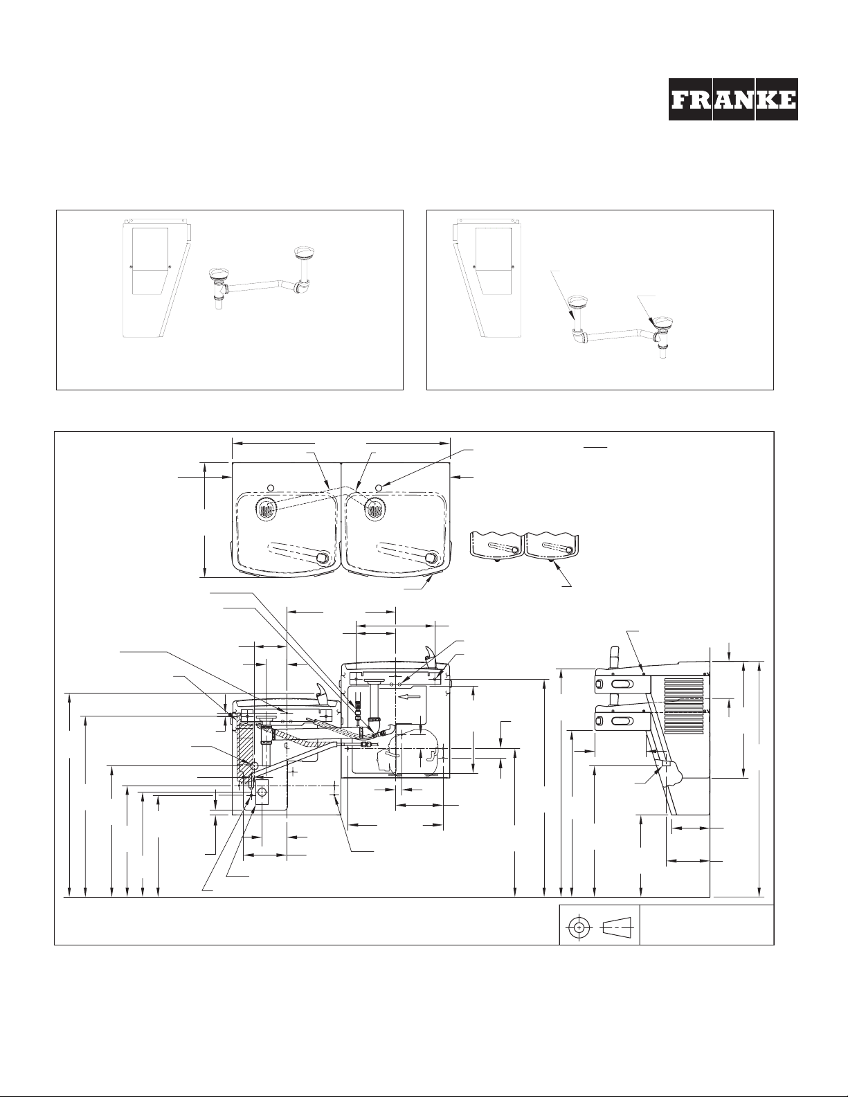
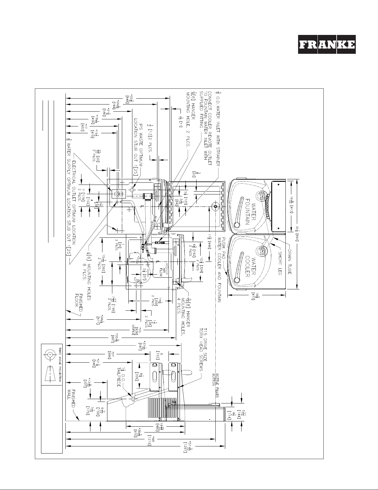
DRINKING FOUNTAIN INSTALLATION
For All Universal Split Level KEP( )ACSL-EBF Series Drinking Fountains
with Electronic Bottle Filler