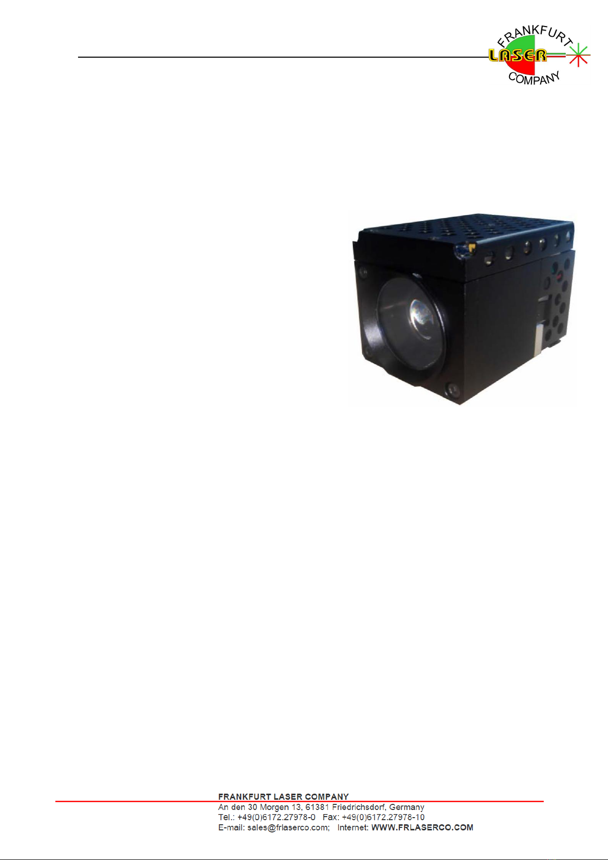
3.2 Product description
This laser illuminator is designed with independent patented technology and self-developed
VSCEL chips. To ensure the reliability of the laser illuminator, a unique photoelectric isolation
design is adopted. To facilitate integration, standard interface parameters such as power supply
and control signals are adopted. It is suitable for dome cameras and bullet cameras for security
monitoring systems and is a high-quality infrared lighting source.
Multi-protocol is used to facilitate customer integration. There are both industry wide Pelco
D protocol and industry protocol, as well as Sony
VISCA protocol for cameras, and FLC protocol.
During the laser angle conversion process, the user
can set the preset position, and then call the preset
position, the laser can automatically adjust the
divergence angle to the set angle.
VCSEL is used as the laser source of this illuminator.
It has wide operating temperature range, long lifetime
and high reliability, higher PCE with lower power
consumption and environmentally friendly. Lower
optical density with its larger emitting area. It has the
advantages of maintenance-free, high beam quality,
uniform and delicate light spot, no fringes and dry
spots, easy integration, and convenient use in special occasions.
3.3 Feature
3.4 Applications
•Security surveillances
•High performance VCSEL chip, no attenuation
•High efficiency up to 40%@25°C, >35%@50°C
•VCSEL chip, wide operating temperature -40~85°C
•VCSEL array chip with large emission area, good safety
•Motorized large dynamic beam angle zooming
•High reliability, lifetime up to 50,000hrs
•Compact, easy to integrate
•RS232, RS485, TTL interface optional
•Negligible off-axis divergence, easy to
collimate with camera lens
•Uniform beam intensity, speckle free
•Operating state memory
•CE certified
•Predefining position
•Low heat, high efficiency