Oriel IQE-LIGHT-BIAS User manual

M
F
a
I
Q
od
e
a
mily of Brands
–
M
Q
E Li
U
e
l I
Q
–
Corion
®
• New
F
M
IQE-LIGHT-
B
ght
B
U
ser'
s
Q
E
-
F
ocus™ • Oriel
®
I
n
B
IAS R
e
B
ia
s
s
Ma
n
-
LI
G
n
struments • Rich
a
e
v: 08/2015
s
ing
n
ual
G
H
T
a
rdson Gratings™
Sys
t
T
-
B
• Spectra-Physic
t
em
B
IA
S
s
®
S

IQE-LIGHT-BIAS
ORIEL®FIBER OPTIC ILLUMINATOR
Page 2
TABLE OF CONTENTS
FIGURES
FIGURE 1: MOUNTING ADAPTER INSTALLATION .................................................................................. 4
FIGURE 2: GLASS FILTER INSTALLATION .............................................................................................. 5
FIGURE 3: FILTER HOLDER ASSEMBLY.................................................................................................. 6
1INTRODUCTION .................................................................................................................................. 3
2INSTALLATION .................................................................................................................................... 4
3THE FIBER BUNDLE ........................................................................................................................... 7
4COLORED GLASS FILTERS............................................................................................................... 8
5PRODUCTS FOR CARE AND MAINTENANCE.................................................................................. 9
6REPLACEMENT PARTS ................................................................................................................... 10
7FIBER ILLUMINATOR SETUP........................................................................................................... 11
7.1VOLTAGE SELECTION ....................................................................................................... 11
7.2FIBER OPTIC CONNECTION ............................................................................................. 11
8FIBER ILLUMINATOR OPERATION ................................................................................................. 12
8.1LAMP INTENSITY CONTROL ............................................................................................. 12
8.2MANUAL .............................................................................................................................. 12
8.3REMOTE INTERFACE......................................................................................................... 12
8.4REMOTE INTENSITY CONTROL ....................................................................................... 13
8.5LAMP FAIL SIGNAL:............................................................................................................14
9FIBER ILLUMINATOR LAMP MODULE REPLACEMENT ................................................................ 15
10FIBER ILLUMINATOR LAMP REPLACEMENT................................................................................. 16
11FIBER ILLUMINATOR FUSE REPLACEMENT ................................................................................. 17
12FIBER ILLUMINATOR SPECIFICATIONS ........................................................................................ 18
13DECLARATION OF CONFORMITY................................................................................................... 19
14WARRANTY AND SERVICE ............................................................................................................. 20

IQE-LIGHT-BIAS
ORIEL®FIBER OPTIC ILLUMINATOR
Page 3
1 INTRODUCTION
The IQE-LIGHT-BIAS kit is used with Oriel’s IQE System when either white or colored biasing illumination
is needed. The light biasing source is adjusted manually.
This kit provides a light source with adjustable intensity levels and the means to install up to three
different colored filters when needed to bias a junction.
The kit includes an external quartz tungsten halogen light source, mounting flange, bifurcated fiber optic
cable and filter holder. A wide selection of filters are available from Oriel to meet a variety of testing
needs. These filters are purchased separately.
Prior to installation, read this instruction manual and all other documentation that came with this kit.
Check to ensure that all parts have been included with the kit. If there are any questions or concerns,
contact Oriel Instruments before installing this kit into the IQE system.
Included items:
66088 Light Source, with power cord and manual
90031273 Filter Assembly
77533 Bifurcated Fiber Bundle
77646 Focusing Beam Probe, with instruction sheet
Mounting and Light Adapters
77371-2-2900 Filter Wrench

IQE-LIGHT-BIAS
ORIEL®FIBER OPTIC ILLUMINATOR
Page 4
2 INSTALLATION
Read all included documentation to understand the handling and care required for each of the system’s
components prior to beginning the installation.
1. Place the fiber light source in a convenient location where the power cord can reach the electrical
mains and the interface cord can reach the IQE system. This location must be less than 36
inches from the IQE System beam splitter assembly.
2. Attach the power cord to the fiber light source and complete all electrical connections.
3. Affix the filter assembly, minus the filter slide, to the front of the fiber light source by tightening
the thumb screw.
4. Install the mounting adapter onto the bottom output port of the beamsplitter on the IQE system.
When using with the IQE-200B system, it is necessary to first install the 71310 adjustable light
shield on the V-flange output port of the system before installing the mounting adapter. Tighten
the mounting adapter’s (3) set screws [A] to hold it in place. Refer to Figure 1.
5. The mounting adapter assembly includes two holders where the bifurcated fiber bundle’s legs are
installed. Each holder is secured to the mounting adapter with a set screw. Loosen the set
screws [B] so that the holders can swing freely. Refer to Figure 1.
FIGURE 1: MOUNTING ADAPTER INSTALLATION

IQE-LIGHT-BIAS
ORIEL®FIBER OPTIC ILLUMINATOR
Page 5
6. Install the optional colored filters into the filter slide as shown in Figure 2 using the filter wrench
provided, or a spanner wrench, to tighten the retaining rings. Do not over tighten, as this will
damage the filters.
Note that the filter slide must have at least one of the filter locations left open (without a filter)
when white light biasing is required. Leave the retaining ring installed so that it does not get
misplaced.
FIGURE 2: GLASS FILTER INSTALLATION
7. Install the filter slide into the filter assembly, taking care that it is oriented exactly as shown in
Figure 3. The filter slide must be installed even if only white light biasing is desired, to prevent
light leakage.
8. Affix both 77646 beam probes onto the two legs of the 77533 fiber bundle. Refer to the
instructions provided with the beam probes. Ensure that the set screws on the beam probe
bodies are backed out far enough so as not to interfere with the fiber insertion and possibly cause
damage to the end face.
9. Install the common end of the fiber bundle into the filter slide and tighten the retaining screws,
after ensuring that the screws on the filter holder are backed out far enough so as not to interfere
with the fiber insertion and possibly cause damage to the end face.
10. Install each leg with its beam probe into the mounting adapter holders. Tighten the set screws [C]
as shown in Figure 1 to secure the fiber.

IQE-LIGHT-BIAS
ORIEL®FIBER OPTIC ILLUMINATOR
Page 6
11. Ensure that the beam probes are not aimed at the eyes of any person. Then turn on the fiber
light source and move the fiber holders on the mounting adapter until the desired light output
onto the sample is achieved. Tighten the set screws to secure the holders in place.
FIGURE 3: FILTER HOLDER ASSEMBLY

IQE-LIGHT-BIAS
ORIEL®FIBER OPTIC ILLUMINATOR
Page 7
3 THE FIBER BUNDLE
The bifurcated glass fiber bundle included with the Light Bias Kit is comb randomized to produce evenly
divided outputs. When light is uniformly focused onto the common end, each leg can transmit 43% of the
total incident energy. The common end and the two legs are all terminated with standard Oriel 11 mm
ferrules.
The fibers in the glass bundle are protected by an interlocking stainless steel sheathing. However, this
bundle is sensitive to position changes. Changing the position of the common end or either leg will
change the output beam distribution and power. To maintain consistent test conditions, avoid movement
of the fiber after the light bias kit has been installed.
Care must be exercised when setting up and storing the glass bundle. Never touch the end faces of the
fiber or allow them to be contaminated by dust or solvents. Incorrect handling will result in breakage of
the glass fibers within the stainless steel sheathing and decreased light output. It is strongly
recommended to save the original packaging for storage.
The minimum bend radius for this fiber bundle is two (2) inches. This bend radius should never be
attempted for the first ¾” after the termination. Minimum bend radius is defined as the smallest radius a
fiber cable can bend before increased attenuation or breakage occurs, as measured from the inside
curvature.
FIBER BUNDLE SPECIFICATIONS
Numerical
Aperture
Acceptance
Cone
Common
Bundle
Diameter
Inch (mm)
[A]
Common
End Tip
Diameter
Inch (mm)
[B]
Common
End Tip
Length
Inch (mm)
[C]
Total
Length
Inch (mm)
[D]
Leg Bundle
Diameter
Inch (mm)
[E]
Leg End Tip
Diameter
Inch (mm)
[F]
Leg End Tip
Length
Inch (mm)
[G]
0.56 68˚4.5
(114)
6.4
(163)
0.50
(12.7)
36
(914)
3.2
(82)
4.75
(121)
12.7
(323)

IQE-LIGHT-BIAS
ORIEL®FIBER OPTIC ILLUMINATOR
Page 8
4 COLORED GLASS FILTERS
Oriel colored glass filters serve as broadband, band pass, or long-wave pass filters. A variety of Schott
color glasses covering the visible and near-infrared wavelength regions are offered. These filters are
precision polished for demanding research or OEM applications.
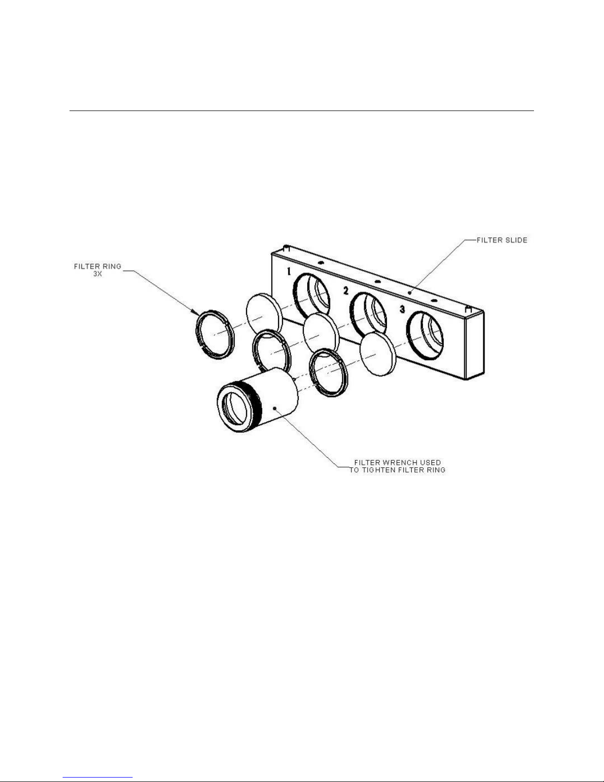
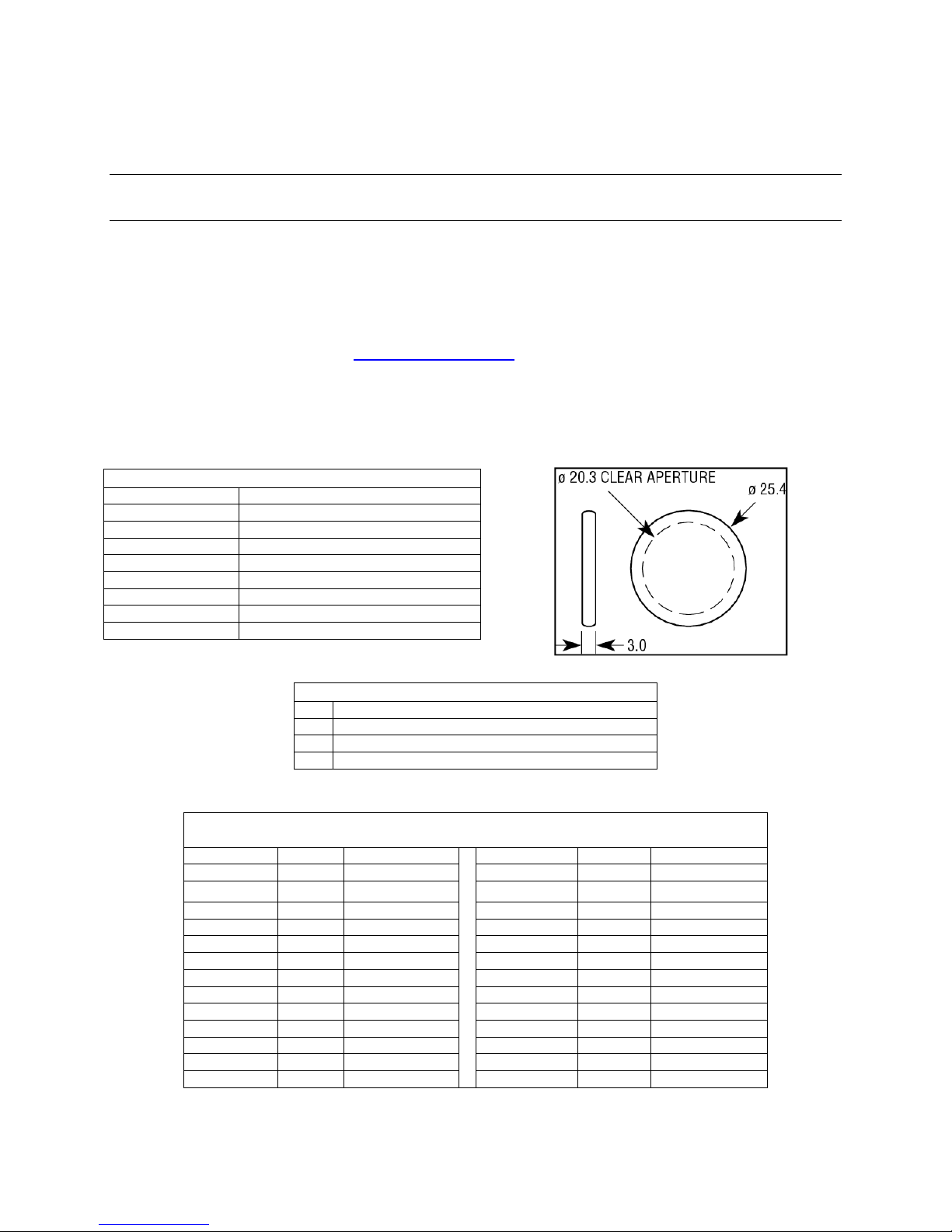
The light bias kit accepts 25.4 mm (1 inch) diameter filters. For easy identification, the filters are
permanently labeled with the glass type. Transmission curves for each filter type listed, as well as
additional filters, may be viewed at www.newport.com/oriel.
To prevent breakage, the glass filters must always be removed from the filter holder prior to transporting
or shipping the light bias kit.
SPECIFICATIONS
Material Schott colored glass or equivalent
Clear Aperture ≥central 80% of dimensions
Surface Quality 60-40 scratch-dig
Dimensions ±0.3 mm
Thickness 3.0 ±0.1 mm
Wedge ≤3 arc min
Chamfers 0.25–0.76 mm face width x 45° ±15°
Angle of Incidence 0°
Damage Threshold 30 W/cm
2
CW, typical
SCHOTT GLASS DESIGNATIONS
BG Blue, blue-green, and multi-band glasses
GG Nearly colorless to yellow glasses, IR transmitting
OG Orange glasses, IR transmitting
RG Red and black glasses, IR transmitting
COLORED GLASS FILTERS
(25.4MM DIAMETER)
Model Glass Description Model Glass Description
FSR-BG18 BG.18 Blue Band pass FSR-OG590 OG.590 Cut-on 590 nm
FSR-BG38 BG.38 Blue Band pass FSR-RG610 RG.610 Cut-on 610 nm
FSR-BG39 BG.39 Blue Band pass FSR-RG630 RG.630 Cut-on 630 nm
FSR-BG40 BG.40 Blue Band pass FSR-RG645 RG.645 Cut-on 645 nm
FSR-GG420 GG.420 Cut-on 420 nm FSR-RG665 RG.655 Cut-on 655 nm
FSR-GG435 GG.435 Cut-on 435 nm FSR-RG695 RG.695 Cut-on 695 nm
FSR-GG455 GG.455 Cut-on 455 nm FSR-RG715 RG.715 Cut-on 715 nm
FSR-GG475 GG.475 Cut-on 475 nm FSR-RG9 RG.725 Cut-on 725 nm
FSR-GG495 GG.495 Cut-on 495 nm FSR-RG780 RG.780 Cut-on 780 nm
FSR-OG515 OG.515 Cut-on 515 nm FSR-RG830 RG.830 Cut-on 830 nm
FSR-OG530 OG.530 Cut-on 530 nm FSR-RG850 RG.850 Cut-on 850 nm
FSR-OG550 OG.550 Cut-on 550 nm FSR-RG1000 RG.1000 Cut-on 1000 nm
FSR-OG570 OG.570 Cut-on 570 nm

IQE-LIGHT-BIAS
ORIEL®FIBER OPTIC ILLUMINATOR
Page 9
5 PRODUCTS FOR CARE AND MAINTENANCE
As part of the Newport family of brands, Oriel Instruments is able to offer a variety of items needed for the
care and maintenance of optics. The appropriate cleaning method varies according to the material and
application for which it is being used. Some of the products available are listed below. For more
products and information, please visit the Oriel Instruments website at www.newport.com/oriel.
DUST REMOVAL
LAB-16 Canned Duster, 10 oz. (300 ml)
LAB-15 Bulb Blower
PROTECTIVE BAGS
LAB-26 white polyester, 50.8 mm square, quantity 10, holds 25.4 mm to 38.1 mm diameter optics
OPTICS CLEANING TISSUE
LAB-28 Optics Cleaning Tissue, 4” x 6” (10.2 mm 15.2 mm), quantity 1000
LAB-10 Cotton Swabs, quantity 1000
LAB-11 Micro Absorbond™ Swabs by Texwipe, quantity 500
MATERIAL HANDLING
LAB-17 Hemostats
LAB-18 Precision Stainless Steel Tweezers
LAB-19 Soft-tip Precision Stainless Steel Tweezers
LAB-20 Teflon®Tweezers
LAB-01 Finger Cots, Small quantity 720
LAB-02 Finger Cots, Medium quantity 720
LAB-03 Finger Cots, Large quantity 720
LAB-04 Gloves, Small quantity 100
LAB-05 Gloves, Medium quantity 100
LAB-06 Gloves, Large quantity 100

IQE-LIGHT-BIAS
ORIEL®FIBER OPTIC ILLUMINATOR
Page 10
6 REPLACEMENT PARTS
All items listed that come with the light bias kit may be purchased separately. Copies of all instructions
can be provided. Additionally, the following replacement parts may also be purchased at any time from
Oriel Instruments. For pricing and lead times, United States and Canadian customers should contact the
Oriel Service Department. All other customer must contact their regional sales representative.
ITEM PART NUMBER
Filter Holder Ring 244-6040-501
Filter Wrench*77371-2-2900
Allen Hex Wrench, #1/16 90-11-042
Power Cord, U.S. plug to IEC320 70010
Power Cord, Europe plug to IEC320 70012NS
Other power cords Contact Oriel Instruments
Quick Disconnect Lamp Socket Contact Oriel Instruments
Nosepiece adapter for .43 OD fibers 77817
Lamp, QTH ZIV, 150W 6346
*As an alternative to using the filter wrench, spanner wrench part number
SW-OM may be ordered instead. The spanner wrench is adjustable so
that it can be used for 6.35 mm to 50.8 mm diameter optics.
NOTICE: if the equipment is used in a manner not specified by the manufacturer, the protection
provided by the equipment may be impaired.

IQE-LIGHT-BIAS
ORIEL®FIBER OPTIC ILLUMINATOR
Page 11
7 FIBER ILLUMINATOR SETUP
7.1 VOLTAGE SELECTION
The 66088 illuminator has universal AC voltage input. Connect the appropriate AC line cord to the DC950
and connect to an AC power receptacle. The 66088 can operate with line voltages from 100 to 250 VAC
and at 50 Hz. or 60 Hz..
7.2 FIBER OPTIC CONNECTION
Notice:
Do not operate the illuminator without the fiber optic connected to the illuminator.
Loosen the fiber optic nosepiece thumbscrew.
Insert the fiber optic into the illuminator nosepiece.
Tighten the thumbscrew by hand to make a secure connection to the fiber optic. Use of pliers or
other tools is not recommended.

8 FIB
E
Insert th
e
cord into
illuminat
o
8.1
L
All the 6
6
an extern
back pan
e
8.2
M
The illumi
0 positio
n
The 100
p
NOTE: C
o
Operatin
g
8.3
R
To enabl
e
REMOT
E
active. S
e
is not co
n
Control P
E
R ILLU
M
e
power cord
a 3 wire gro
u
o
r.
L
AMP INT
E
6
088 series ill
al interface (
e
l.
M
ANUAL
nator intensi
t
n
(when cont
r
p
osition (whe
n
o
ntinuous op
e
g
the illumina
t
R
EMOTE I
N
e
the remot
e
position. W
h
e
e Fig. B for t
n
nected, the
in is connect
e
M
INATO
R
into the po
w
u
nded AC p
o
E
NSITY CO
uminators ar
9-pin, D styl
e
t
y is controlle
d
r
ol is turned f
u
n
control is t
u
e
ration of the
t
or at reduce
d
N
TERFAC
E
e
interface,
m
h
en the swit
c
he Pin Funct
i
illuminator
w
e
d.
R
OPERA
w
er entry mo
d
o
wer recepta
c
NTROL
e
equipped
w
e
connector)
d
by the rota
r
u
lly counter-
c
u
rned fully clo
illuminator a
d
intensity ca
n
E
m
ove the LO
C
c
h is in the
R
i
ons on the 9
w
ill run at th
TION
d
ule at the r
e
c
le. Use onl
y
w
ith a front p
a
for remote i
n
r
y control loc
a
c
lockwise) co
ckwise) corr
e
t the highest
n
result in sig
n
C
AL/REMOT
E
R
EMOTE po
s
Pin D-Sub c
o
e maximum
e
ar of the illu
m
y
approved
p
a
nel manual
n
tensity cont
r
a
ted on the fr
o
rresponds to
e
sponds to th
e
intensity lev
e
nificantly ext
e
E
, located o
n
s
ition the fro
n
o
nnector. If t
h
intensity set
t
ORIEL
®
FIBE
R
m
inator. Ne
x
p
ower cord
s
solid state in
r
ol via a 0-5
V
o
nt panel of
t
the lowest il
l
e
highest illu
m
e
l may yield
s
e
nded lamp l
i
Rem
o
Conn
e
Local
Switc
h
A
C P
o
n
the rear p
a
n
t panel inte
n
h
e Remote I
n
t
ing until th
e
IQE-LIGH
R
OPTIC ILLUMI
N
P
x
t, insert the
p
s
upplied wi
t
tensity contr
o
V
DC signal
o
t
he illuminato
l
uminator int
e
m
inator inten
s
s
hortened la
m
i
fe.
o
te Interface
e
ctor
/ Remote S
e
h
o
wer Entry
a
nel of unit,
t
n
sity control
n
tensity Cont
r
e
Remote Int
T-BIAS
N
ATOR
P
age 12
p
ower
t
h the
o
l and
o
n the
r. The
e
nsity.
s
ity
.
m
p life.
e
lector
t
o the
is not
r
ol Pin
ensity

IQE-LIGHT-BIAS
ORIEL®FIBER OPTIC ILLUMINATOR
Page 13
8.4 REMOTE INTENSITY CONTROL
The Remote Intensity Control is located on Pin 3 of the Remote Interface. When the LOCAL/REMOTE
switch is in the REMOTE position the intensity is controlled by the signal applied to Pin 3. NOTE: The
front panel intensity control is deactivated in remote mode.
The input signal must be limited to a 0 to +5 volt DC signal. A negative voltage or a voltage in excess of 5
volts will cause the lamp to run at maximum intensity potentially shortening lamp life. The DC950 Remote
Intensity control is highly linear. At 0 volts the lamp voltage is 0 volts. At +5 volts the lamp voltage is the
maximum voltage for the lamp specified at the time the order was placed. A 2.5 volt input signal will
cause the lamp to run at 50% of lamp voltage. Refer to Table A for intermediate values.
Pin 1 can be used to supply power to a remote potentiometer. Connect the potentiometer as shown in
Figure C. The 500 ohm series resistor prevents shorting the power supply on Pin 1 if the potentiometer
should fail as a short circuit. In all cases the minimum resistance between Pin 1 and common ground
(Pins 2 and 7) must be at least 500 ohms to prevent damage to the Pin 1 power supply.
The user may also use a fixed voltage divider to control the illuminator at a non-varying intensity level.
Refer to Figure E and the resistance values in Table A for sample resistor values and the corresponding
lamp intensity levels. In all cases, the minimum total resistance value connected between Pin 1 and
common ground (Pins 2 and 7) must be 500 ohms (RA + RB > 500 ohms.)
The lamp power can be controlled via Pin 6, see Fig A. By
connectingPin 6 to a logic high (+5v) signal(Pin 1) the lamp power will
be interrupted for as long as Pin 6 is connected to logic high. When
the contacts connecting Pin 6 are opened, removing the +5v from
Pin ,the illuminator will return to the intensity level set by the signal
connected to Pin 3 or to the intensity level set by the front panel
control. The response time of the illuminator going from On to Off and
Off to On is dependent on the thermal response of the lamp. The lag
time of the lamp may be several hundred milliseconds from the time
the Remote On-Off signal is applied to the time the lamp attains either
the full On or full Off state. The response time of the power supply is
less than 100 milliseconds.
B
A

IQE-LIGHT-BIAS
ORIEL®FIBER OPTIC ILLUMINATOR
Page 14
8.5 LAMP FAIL SIGNAL:
A signal indicating that the lamp has failed is available on Pin 9. This signal is open collector (see Fig D).
The user must supply the necessary circuitry to connect the lamp out signal to a signaling device. The
maximum current through the circuit is 10 mA. When the signal at Pin 9 is logic High(5v) the lamp has
failed.
The Lamp Fail signal will detect if current has stopped flowing to the lamp while the intensity control
signal is not at 0 volts, the illuminator On-Off switch is in the On position, and the Remote On-Off signal is
in the On condition. The Lamp Fail signal will also indicate if the lamp is not properly seated after a lamp
change, if the lamp power connector is not properly connected after a lamp change, or if the lamp socket
was replaced.
C E
D

IQE-LIGHT-BIAS
ORIEL®FIBER OPTIC ILLUMINATOR
Page 15
9 FIBER ILLUMINATOR LAMP MODULE REPLACEMENT
1. Turn the illuminator intensity control fully counterclockwise (the 0 position) and run the illuminator with
the fan for several minutes. Wait until the nosepiece is cool to the touch. Press the ON(1)/OFF(0)
rocker switch to the OFF(0) position.
2. Remove the AC line cord from the AC power receptacle.
3. Release lamp module from the power supply by turning both retaining screws counterclockwise using
a straight blade screwdriver. NOTE: Both retaining screws will be disengaged from the power supply,
but will remain in place in the lamp module.
4. Remove the lamp module from the front panel of the light source by slowly pulling outward.
5. Release the lamp module by unlatching the quick disconnect lamp cord. See Fig F.
6. Attach new lamp module by connecting the quick disconnect lamp cord.
7. Insert lamp module into power supply. Make sure lamp cord does not interfere.
8. Secure lamp module by tightening the (2) retaining screws
9. Reattach AC line cord and the illuminator is ready for service.
F

IQE-LIGHT-BIAS
ORIEL®FIBER OPTIC ILLUMINATOR
Page 16
10FIBER ILLUMINATOR LAMP REPLACEMENT
1. Follow steps 1-4 of Lamp Module Replacement.
2. Check the lamp assembly to verify that the lamp and socket are cool before proceeding.
3. Lift and remove the lamp from the lamp holder by grasping the rear of the lamp adjacent to the lamp
socket.
4. Remove the lamp from the socket by holding the lamp socket and gently pulling the lamp reflector.
5. Discard the lamp.
6. Insert the replacement lamp into the lamp socket. CAUTION: Do not touch the interior of the lamp
reflector, the lamp envelope, or the lamp pins with your fingers. Touching the interior of the lamp
reflector, the lamp envelope, or the lamp pins will result in significant shortening of the lamp life.
Handle the lamp only by the exterior of the reflector or the area adjacent to the pins.
7. Insert the replacement lamp and socket into the lamp holder.
8. Follow steps 7-9 of Lamp Module Replacement.

IQE-LIGHT-BIAS
ORIEL®FIBER OPTIC ILLUMINATOR
Page 17
11FIBER ILLUMINATOR FUSE REPLACEMENT
1. Press the ON(1)/OFF(0) switch to the OFF(0) position.
2. Remove the AC line cord from the AC power receptacle.
3. Remove the AC line cord from the power entry module at the rear of the illuminator. The fuse
drawer is part of the power entry module. The drawer is located directly beneath where the AC line
cord plugs in.
4. Pull out the fuse drawer. Remove the blown fuse that is positioned closest to the illuminator and
discard. The second fuse is the spare.
5. Place the replacement fuse into the fuse drawer. The fuse should work in either orientation. The
recommended fuse should be rated at 3.15 A, 250V, time delay, 5 x 20 mm.
6. Push the fuse drawer until it "clicks" into position.
7. Attach the AC line cord to power entry module at the rear of the illuminator. The illuminator is now
ready for service.

IQE-LIGHT-BIAS
ORIEL®FIBER OPTIC ILLUMINATOR
Page 18
12 FIBER ILLUMINATOR SPECIFICATIONS
F/# F/1.1
Lamp Voltage 21 VAC, nominal; adjustable from 0 - 21 VAC
Lamp Input Power 150 W, nominal
Lamp Life 200 – 10,000 hours depending on intensity level
Color Temperature 3200° Kelvin at max. intensity
Light Output Regulation ±0.5% or better
Light Ripple ±6% pk. to pk.
Intensity Control solid state 0-100%
AC Line Input 100/240 VAC, 50/60 Hz
Remote Intensity Control 0-5 VDC analog, optional 8-bit digital or RS232
Dimensions 7.25" x 9.50" x 4.6"
Weight <15.0 lbs.
Approvals UL/c-UL, CE
NOTICE: if the equipment is used in a manner not specified by the manufacturer, the protection
provided by the equipment may be impaired.

13
D
Man
u
Man
u
Decl
conf
o
com
p
and
a
D
o
Sit
15
St
r
D
ECLAR
A
u
facturer’s n
a
u
facturer’s a
d
ares that the
Produc
Model
N
Type o
f
o
rms to the f
o
Safety:
EMC:
p
lies with the
a
ccordingly,
mark affi
x
o
menic Assal
o
e
Manager,
O
0 Long Beac
h
r
atford, CT 0
6
A
TION O
F
EC
D
a
me:
d
dress:
product:
t Name:
N
umber:
f
equipment:
o
llowing Prod
following Dir
e
carries the
x
ed:
o
ne
O
riel Product
s
h
Boulevard
6
615 US
A
F
CONF
O
D
ECLARAT
S
E
l
uct Specifica
t
e
ctives:
mark
s
Division
A
O
RMITY
ION OF C
O
Newport Cor
p
150 Long Be
a
S
tratford, CT
IQE Light B
i
IQE-LIGHT
-
E
lectrical eq
u
l
aboratory us
e
t
ions:
EN 61010-1:
EN 61326-1:
2004/108/E
C
2006/95/EC
L
Beaune; 12
/
Bruno Re
t
document
a
Group Dir
e
Micro-Co
n
Zone Indu
45340 Be
a
O
NFORMIT
Y
p
oration
a
ch Bouleva
r
06615 U
i
asing Syst
e
-
BIAS
u
ipment for m
e in industria
2010
2006 +cor:2
0
C
EMC Direct
i
Low Voltage
/
01/2010
t
y Authorize
d
ation
e
ctor, PPT I
n
n
trole Divisio
n
u
strielle
a
une la Rola
n
ORIEL
®
FIBE
R
Y
r
d
S
A
e
m
m
easurement,
l locations
0
08 +cor:201
0
ive
Directive
d
to compile t
e
n
strument an
d
n
of Newport
C
n
de, France
IQE-LIGH
R
OPTIC ILLUMI
N
P
control and
0
e
chnical
d
Motion Eur
o
C
orporation
T-BIAS
N
ATOR
P
age 19
o
pe

IQE-LIGHT-BIAS
ORIEL®FIBER OPTIC ILLUMINATOR
Page 20
14 WARRANTY AND SERVICE
CONTACTING ORIEL INSTRUMENTS
Oriel Instruments belongs to Newport Corporation's family of brands. Thanks to a steadfast
commitment to quality, innovation, hard work and customer care, Newport is trusted the world over
as the complete source for all photonics and laser technology and equipment.
Founded in 1969, Newport is a pioneering single-source solutions provider of laser and photonics
components to the leaders in scientific research, life and health sciences, photovoltaics,
microelectronics, industrial manufacturing and homeland security markets.
Newport Corporation proudly serves customers across Canada, Europe, Asia and the United
States through 9 international subsidiaries and 24 sales offices worldwide. Every year, the
Newport Resource catalog is hailed as the premier sourcebook for those in need of advanced
technology products and services. It is available by mail request or through Newport's website.
The website is where one will find product updates, interactive demonstrations, specification charts
and more.
To obtain information regarding sales, technical support or factory service, United States and
Canadian customers should contact Oriel Instruments directly.
Newport Corp - Oriel Instruments
31950 E Frontage Rd
Bozeman, MT 59715 USA
Telephone: 877-835-9620 (toll-free in United States)
949-863-3144
Fax: 949-253-1680
Sales: [email protected]
Customers outside of the United States must contact their regional representative for all sales,
technical support and service inquiries. A list of worldwide representatives can be found on
Oriel's website: http://www.newport.com/oriel.
REQUEST FOR ASSISTANCE / SERVICE
Please have the following information available when requesting assistance or service:
Contact information for the owner of the product.
Instrument model number (located on the product label).
Product serial number and date of manufacture (located on the product label).
Description of the problem.
Table of contents
Popular Lighting Equipment manuals by other brands

Dale Tiffany
Dale Tiffany TB11030 Assembly instructions

Spectronics
Spectronics Spectroline TRITAN 450 AC quick start guide

All Pond Solutions
All Pond Solutions PLED-310 manual

Lightmybricks
Lightmybricks LEGO HOGWARTS EXPRESS COLLECTORS EDITION installation guide

Lightmybricks
Lightmybricks LEGO Winter Village Station manual

MegaLite
MegaLite Drama W50 LED user manual

Show Tec
Show Tec Scorpion Scan 260 manual

In Light
In Light IN-0113-3 Series installation guide

JB Systems Light
JB Systems Light Super LED Rainbow Operation manual

Astral Pool
Astral Pool Glassy L Installation, operation and manteinance manual

Jolly line
Jolly line Black Easy Light quick start guide

afx light
afx light MINIBEAM32 instruction manual