Franklin VFD 1 User manual

12VDC Transducer
(FCS Provided)
Pump Quickstart Guide
Wiring
Verify correct input voltage
and wiring to the VFD power
and motor terminals. Connect
3-phase input power wires
to VFD terminals R, S & T or
single-phase power wires to
VFD terminals R & S.
Connect 3-phase motor wires to
VFD terminals U, V & W.
Connect power source ground
wire and motor ground wire to
VFD ground terminal.
DRVT/K 0.0A
00 STP 0.00Hz
Mode: Use to cycle through parameter groups:
SET>DRV>FG1>FG2>....
Up & Down: Use to cycle through parameters
of the current group. Use to adjust parameters
when in programming mode.
Loc/Rem: Toggles between Local and Remote
operation
Enter: Use to enter programming mode of
any parameter as well to submit a change.
A ashing cursor will appear when VFD is in
programming mode.
Shift: Use to cycle backwards through
parameter groups. When in programming
mode, use to shift cursor to the right (one
position per press).
Rev, Stop/Reset & Fwd: Use to Start and Stop
VFD Forward or Reverse in Local mode. Use
Stop to reset VFD fault.
1
2
3
45
6
Keypad Programming
1
2
3
4
5
6
VFD Only
Enclosed VFD
Verify correct input voltage and
wiring to enclosed VFD panel
power and motor terminals.
Connect 3-phase input power
wires to enclosure or disconnect
terminals L1, L2 & L3 or single-
phase power wires to terminals
L1 & L2.
Connect 3-phase motor wires to
enclosure terminals T1, T2 & T3.
Connect power source ground
wire and motor ground wire to
enclosure ground terminal.
Warning: Input, Output and Control wiring must be in separate conduits
Note: Do not wire any wire to the DC bus “P1”, “P2” & “N” terminals.
L1
L2
L3
L1
L2
L3
L1
L2
L1
L2
Transducer verication – From main DRV-00 screen
go to DRV-98 by pressing Down key . The reading is in
4-20mA range and it should match to transducer output
current. If reading is less than 4mA, verify transducer wir-
ing and voltage on V+ and 24 terminals.
Enclosed Drive Instructions:
(terminals mounted on back panel)
Stand Alone Drive Instructions:
Transducer placement: Placing the transducer too
close to the pump discharge may cause oscillations and
improper operation of the VFD.
Note: If two transducers are used for redundancy, refer to
VFD manual for details.
Main Display: DRV - Current parameter group. (SET, DRV, FG1, FG2, I/O, APP, EXT & COM)
00L - Shows the current parameter number within a current group. An ‘L’ will appear when VFD is switched
to Local control mode by either LOC/REM key or digital input.
T - Shows source for VFD start/stop operation (T = Remote, K= Keypad, O= Communication Protocol).
K - Shows source for VFD frequency command (K= Keypad, V= 0-10VDC, I= 4-20mA, O= Communication)
0.0A - Shows the actual motor current
STP - Shows the current status of the VFD (STP = Stop, FWD = Forward, REV = Reverse)
0.00Hz - Shows frequency reference or PID set-point in VFD stop mode and actual VFD output frequency
in VFD run mode.
R S T G P1 P2 N U V W
L1 L2 L3 L1 L2 L3
T1 T2 T3 T1 T2 T3
M
M
M M
3-PHASE POWER
3-PHASE POWER SINGLE-PHASE POWER
ENCLOSED VFD ENCLOSED VFD
SINGLE-PHASE POWER
MOTOR
MOTOR
MOTOR MOTOR
VFD
Terminals
L
VFD
Terminals
Transducer:
franklin-controls.com | 800.962.3787
Terminal Blocks
12 VDC Transducer
(FCS Provided)
AG
V1
(BLACK)
(SILVER)(shield)
(RED)
Terminal Blocks
V+
1. Peel back insulation to expose shield (bare) wire.
Note: Green & White wires should not be used.
2. Wire the pressure transducer's positive RED wire to the
terminal marked V+ for 12VDC and the output BLACK
wire to terminal with the shield wired to AG.
Instructions
12 VDC Transducer
(FCS Provided)
AG
V1
(BLACK)
(SILVER)(shield)
(RED)
Terminal Blocks
V+
12 VDC Transducer
(FCS Provided)
AG
V1
(BLACK)
(SHIELD)(bare wire)
(RED)
Terminal Blocks
V+
*Note: Use “5G” for 7.5-40HP VFDs and “CM” for
VFDs over 40HP
12VDC Transducer (FCS Provided)
*(CM) 5G
V+
I
(BLACK)
(SHIELD) (bare wire)
(RED)
Notes:
1) Put shrink tube or electrical tape on
bare shield wire to prevent short circuit of
any VFD terminals.
2) Wiring may vary for non-FCS provided
transducers
5G
24
I
*(CM)
*Note: For VFD’s 40HP and smaller, wire the
transducer shield to CM and place a wire
jumper between CM & 5G.’
24VDC Transducer
(POWER)
(SHIELD) (bare wire)
(SIGNAL)
WARNING: Submersible pumps can develop very high pressure in some situations. Always use
a properly selected and installed pressure relief valve to prevent damage and injury from over-
pressurization of pipes and tanks. Installation of cut-off pressure switch is recommended.
Control Wiring: The start dry contact should be wired to VFD terminals CM and M7 or 1 and 2 in
enclosed VFD panel. If jumper is installed on start terminals, VFD will run when power turned on.

System Initial Start Up & Control Settings
APPLICATION SELECTION: Select either Submersible or Circulating pump to load preset programming. Refer
to the parameter table at the end of this quick-start for presets.
Verify Rotation
Move HOA switch to AUTO position and the VFD will begin to run the motor. Check the output ow and verify proper rotation. If rotation is
incorrect, stop the VFD, turn the VFD power off and wait 5 minutes. Swap two motor leads to change rotation.
The majority of drive setups can be accomplished by going through only one group; the setup [SET] group. This group was designed to
have start-up specic parameters to make start-up easy. Navigate to the SETUP group [SET] by pressing the SHIFT button once from
the main screen. Your display will show SET in the upper left hand corner of the display.
INPUT POWER # OF PHASES: Default is 3-Phase. Select 1-Phase for single-phase to three-phase conversion
application which will change a motor HP rating setting to 50% of the VFD rating.
RATED MOTOR HP: Put the motor horsepower rating from the motor nameplate.
RATED MOTOR CURRENT: Put the motor FLA (full load amps) rating from the motor nameplate.
PRESSURE TRANSDUCER RANGE: The SET-25 default is for a 0-100PSI transducer. Program the maximum
range of your pressure transducer. E.g. Program a value of 250PSI for a 250PSI transducer.
SET
Input Phase
01 3-Phase
SET
App. Select
00 None
SETMotor HP
02 7.5 HP
SET
F/B Unit Max
25 100.0 PSI
Advanced Control Features
These parameters are set to optimal and safe default settings for the Submersible Pump application and can be changed
in the eld to t application requirements. You may need to adjust some parameters to provide better control for your
system.
Pre-PID is designed for pump systems with long pipes that require lling pipe at every start. Upon PrePID time delay expiration or when
system pressure (PSI) exceeds the PrePID Exit Level, the VFD will switch to PID control and maintain a system pressure at pressure set-
point.
Note: SET-36 is set to 0.0Hz (Pre-PID is disabled by default) and can be enabled by changing SET-36 frequency.
- Pre-PID Settings (Pipe Fill Mode)
PRE-PID FREQUENCY: Navigate to SET-36 and put VFD frequency at which drive will run to ll an empty pipe.
Set this parameter for frequency above PID Low Frequency Limit and VFD will run to ll the pipe system for the
time delay set in SET-37 or until pressure exceeds the exit level set in SET-38. Default setting is 0.0 Hz.
PRE-PID STOP DELAY: This sets the time to ll an empty pipe. Test how much time it takes to ll an empty pipe
during startup and adjust as necessary. Default setting is 180 sec.
PRE-PID EXIT LEVEL: PSI level above which the VFD will switch to PID control mode to maintain a system
pressure at set-point. Default setting is 25 PSI.
SETPrePID freq
36 42.00 Hz
SET
PrePID dly
37 30 sec
SETPrePID Exit
38 25.0 PSI
SETMotor FLA
03 2.2 A
PRESSURE SET-POINT: Set SET-26 to desired pressure (psi) that VFD needs to maintain. The default is 50PSI
and can be changed to any number within pressure transducer range. The pressure Set-point can be changed in
DRV-00 parameter in remote mode too (in local mode it shows Hz).
Parameter Programming Description
1) Press [MODE] or [SHIFT] key until the desired parameter group is displayed.
2) Press UP [▲] or DOWN [▼] keys to scroll to the desired parameter. If you know the desired parameter number, you can set its number
in the rst parameter #00 “Jump code” of any parameter group (except SET and DRV groups) and after pressing [ENTER] key display will
show that parameter.
3) Press [ENTER] key to enter the programming mode, which is indicated by a ashing cursor. Some parameters cannot be changed
during VFD run or fault modes. Refer to the manual to check if desired parameter can be programmed during run.
4) For selectable parameters press [▲] or [▼] keys to change parameter selection.
When programming a numerical value, the value will be changed from maximum to minimum by pressing UP or DOWN key. In order
to change any digit in a numeric value, use the SHIFT key to move the ashing cursor to that digit and UP or DOWN keys to adjust the
selected digit.
5) Press [▲] or [▼] keys to change the digit in numerical parameter value.
6) Press [ENTER] key to nish programming for this parameter. The ashing cursor disappears.
Verify Basic Settings
SET
PID SetPoint
26 50.0 PSI
Determine No-Demand Frequency and PID Frequency Low Limit
PID LIMIT LOW: Turn the HOA switch to Auto position and run system with No demand. When system pressure
is at pressure set-point and frequency is stabilized, add 1Hz to this frequency and set it in SET-27. If system
pressure is above pressure set-point, the rst of three conditions for activation of the Sleep mode is met.
For Flat curve pumps Minimum frequency is typically 53-54Hz.
- Setting Sleep Mode
Sleep mode will stop the VFD in no-demand condition when system pressure is slightly above SET-26 set-point and output frequency is
below SET-32 Sleep mode frequency setting for SET-33 Sleep mode delay time. The most critical step is to determine and set a correct
SET-27 PID Frequency Low Limit.
Sleep Boost Mode: When pump system is ready to go into Sleep mode, it can increase a system pressure by some PSI to prevent
short cycling at low demand changes.
Pipe Leak protection: Refer to VFD manual for detailed description on Dual Demand and Pipe Leak features.
Pump Speed Limit by Well Water Level: Refer to VFD manual for details. Requires well level transducer.
SLEEP MODE FREQUENCY: Set this parameter to [SET-27]+0.5Hz. If VFD frequency is below SET-32, the
second condition for activation of the Sleep mode is met.
SLEEP MODE DELAY TIME: The SET-33 is a delay time to activate Sleep Mode when other two conditions
are met. If any of two above conditions is off, the Sleep Delay Timer will be reset.
SLEEP BOOST: The VFD will boost the system pressure by the programmed in SET-34 value before going to
sleep. Default is 3PSI for submersible and 2PSI for Centrifugal pumps.
Program a value of 0PSI to disable this feature.
SLEEP BOOST TIMER: When VFD is ready for sleep mode it will increase pressure set-point by Sleep Boost
value. When Set-point is met or Sleep Boost Timer SET-47 expires, VFD will activate sleep mode.
SET
PID Limit-L
27 30.00 Hz
SET
Sleep Freq
32 35.00 Hz
SET
Sleep Delay
33 20 Sec
SET
Sleep Boost
34 3.0 PSI
- Broken Pipe Trip
SETPbroken Mode
40 Yes
BROKEN PIPE MODE: Set to YES to enable, NO to disable. Default setting is NO.
If the following three parameters are met simultaneously, VFD will trip on a broken pipe fault.
- UnderLevel Protection (Dry Well)
LEVEL DETECTION: Change SET-74 to NO to disable. Default setting is UnderLevel.
SETLevel Detect
74 Under Level
UNDERLOAD AMPERAGE: Adjust SET-78 to 65-70% of SET-03 (FLA) for submersible and 30-35% for
centrifugal pump. Default setting is 0.0 A.
WELL FILL TIME: If parameter SET-80=YES, SET-81 ll time setting should be sufcient to ll the well before
VFD attempting to start again. Default setting is 60.0 min. If VFD trips again on Under Level fault during restart
attempt, the SET-81 value will be doubled for next restart.
SET
LDT Level
78 0.0 A
Underlevel trip (known as dry well protection) is designed to trip the VFD when the pump motor current draw is less than SET-78 for
SET-77 time delay when VFD output frequency is above SET-76. For submersible pumps it is typically 65-70% and for centrifugal
pumps 30-35%. For the correct adjustment check with motor manufacturer.
Broken Pipe will stop VFD operation if a broken pipe is detected while running in PID control mode to protected from ooding the eld.
For trip specics, please refer to the installation & operation manual
SET
LDT Fill Time
81 60.0 min
WAKE-UP LEVEL: The SET-35 is a percentage of SET-25 pressure transducer range. The VFD will wake-up
if system pressure is less than wake-up pressure that can be calculated [SET-26]-([SET-25]*[SET-35]/100). For
100PSI transducer the SET-35 value equals to PSI (2% would be 2PSI).
SETPbroken F/B
43 50
SETPbrokenFreq
41 59.00 Hz
SETPbrokenDly
42 30 sec
1) If drive is running over the speed indicated in SET 41,
2) If drive is running longer than time indicated in SET 42,
3) If the pressure is below PSI indicated in SET 43.
SETWakeUp Level
35 2%
franklin-controls.com | 800.962.3787
SET Boost Timer
47 10 sec

ATTENTION INSTALLER: PLEASE READ AND FOLLOW THESE INSTALLATION GUIDELINES.
FAILURE TO FOLLOW INSTALLATION GUIDELINES MAY VOID WARRANTY.
A drive is a sensitive piece of power electronics that, when installed properly, will provide you with years of trouble-free operation.
While our drives have many built-in protective features, if the installation or application is incorrect, failures due to improper
protection or installation will not be covered under warranty. To avoid this ugly situation we have developed the Drive Installation
ABC’s. Know these basic ABC’s with every drive you purchase. An incorrectly applied or installed inverter can result in system
malfunction or reduction in product life as well as component damage. You must read and understand the manual thoroughly
before proceeding.
Installation Precautions
1) Handle the VFD with care to prevent damage to
the plastic components. Do not hold the VFD by
the front cover.
2) Do not mount the VFD in a location with vibration
(level higher than 5.9 m/sec2) such as installing the
VFD on a press or other moving equipment.
3) Install in a location where temperature is within the
permissible range.
4) The VFD can be hot during operation. Install it on
a non-combustible surface.
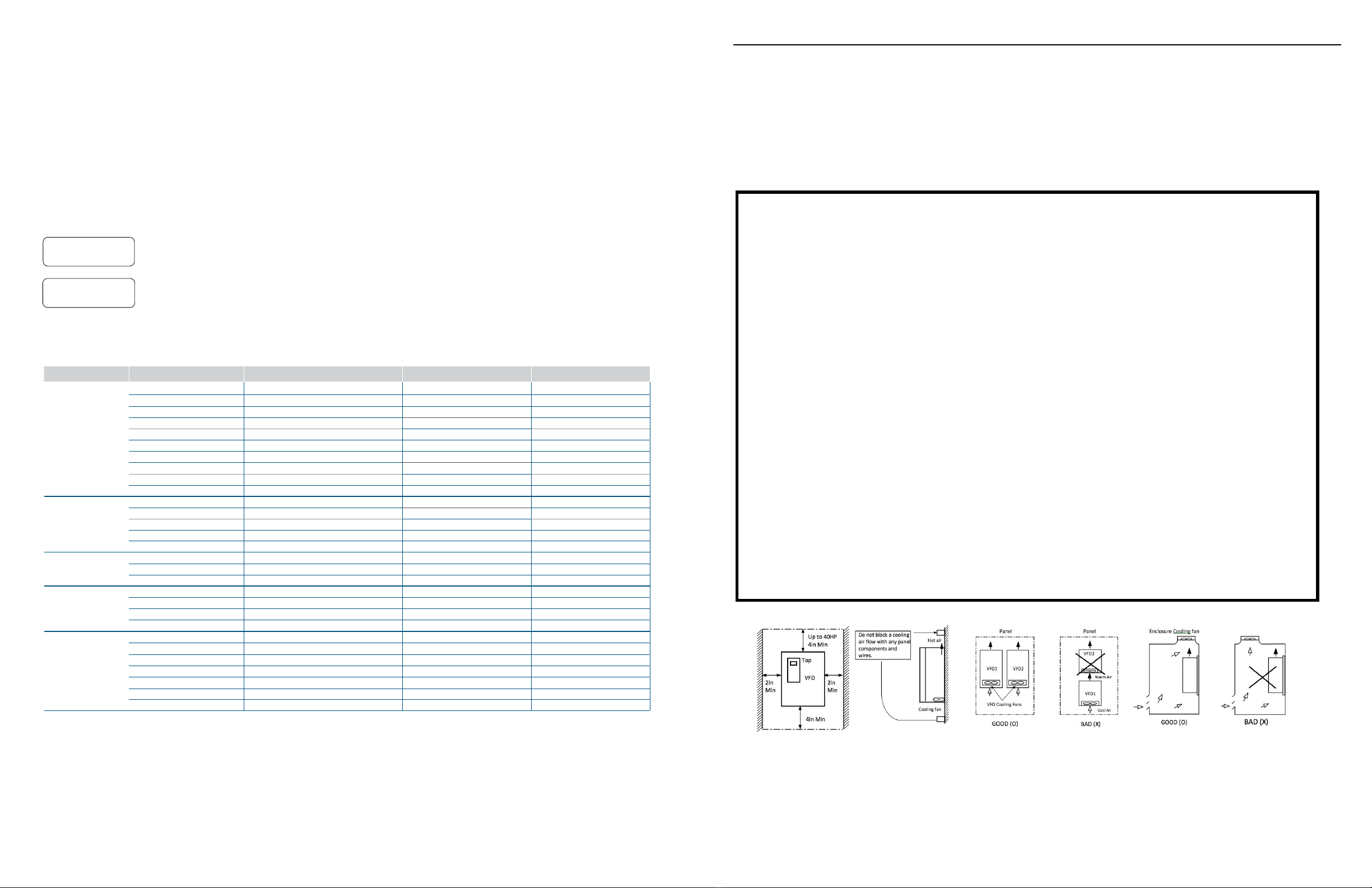
5) Mount the VFD on a flat, vertical, and level surface.
VFD orientation must be vertical (top up) for proper heat
dissipation. Also leave sufficient clearances around the
VFD. Increase minimum clearance by one inch for 50~75 HP
VFDs, by two inches for 100~150 HP VFDs, by three inches
for 200~300 HP VFDs, by four inches for 350~700 HP VFDs
to provide sufficient cooling airflow.
6) Do not mount the VFD in direct sunlight or near other
heat sources.
7) The VFD should be mounted in a Pollution Degree
2 environment. If the VFD is going to be installed
in an environment with a high probability of dust,
metallic particles, mists, corrosive gases, or other
contaminates, the VFD must be located inside the
appropriate electrical enclosure of the proper NEMA
or IP rating.
8) When two or more VFDs are installed or a ventilation
fan is mounted in the VFD panel, the VFD and
ventilation fan must be installed in proper positions
to keep the internal ambient temperature of the VFD
below the permissible value. If they are installed in
improper positions, the ambient temperature of the
VFD will rise.
9) Install the VFD using screws or bolts to ensure the
VFD is firmly fastened.
The ABC’s:
Form CVFDW1 - Ver. 2 Franklin Electric Warranty Registration Form for Variable Frequency Drives
Franklin Electric cannot provide technical support until the installer completes this form and files it with Franklin Technical Support. Only Franklin certified
personnel may use this form for Franklin (Titan) Variable Frequency Drives.
Date of start-up
VFD 1 VFD 2 VFD 3
Part #
Serial #
INSTALLATION INFORMATION
Motor Data
Insulation Class/Rated Voltage
Horsepower/Full Load Amperage HP/ FLA
Service Factor/RPM
Application
Torque constant variable constant variable constant variable
Input phase three-phase single-phase
Description
(i.e. pump jack, centrifuge, fan, blower, etc.)
Maximum & Minimum
Environmental Temperature °F
Distances in feet from VFD to motor
to service
transformer
Startup information
VFD Output Current Parameter
Reading @ Max Speed Amps
Speed control
Keypad 0-10V
Potentiometer 4-20mA
Communication Card
Enclosure NEMA rating 13R 12 4 or 4X 1 3R 12 4 or 4X 1 3R 12 4 or 4X
Check proper wiring & grounding
YES YES YES
VFD parameters set according
to quick start guide?
INSTALLER INFORMATION PURCHASER INFORMATION
Name
Phone
Company/Address
Installation date Install Location Purchase date PO #
Date of start-up Date of start-up
to motor
to service
transformer
to motor
to service
transformer
Input Voltage on VFD terminals
R, S, & T R-SS-TR-T R-S S-TR-T R-SS-T R-T
PID
Keypad 0-10V
Potentiometer 4-20mA
Communication Card PID
Keypad 0-10V
Potentiometer 4-20mA
Communication Card PID
VFD enclosed by?
Enclosure dimensions in inches
Cooling Fan/AC Unit Size
H W D H W D H W D
/ VIns.
/ V
Ins.
/ V
Ins.
HP/ FLA HP/ FLA
SF/ RPM
SF/ RPM
SF/ RPM
Max: °F
Min: °F
Max: °F
Min: °F
Max: °F
Min:
(see manual
for parameter) Amps
(see manual
for parameter) Amps
(see manual
for parameter)
Environmental Conditions
(Please select all applicable conditions)
Indoor Dirt/Debris
Outdoor Moisture
Direct Sunlight Chemicals
YES NO YES NO YES NO
Please complete the fields below if the VFD is installed in an enclosed package that was not built by Franklin Electric.
Indoor Dirt/Debris
Outdoor Moisture
Direct Sunlight Chemicals
Indoor Dirt/Debris
Outdoor Moisture
Direct Sunlight Chemicals
Franklin Customer Not
Enclosed
Fan (In.) /AC(BTU) Fan (In.)/AC (BTU)Fan (In.)/AC (BTU)
xaFliamE
Name
Phone
Company/Address
xaFliamE
PURCHASER INFORMATION
Installed Devices
(Indicate the letters of installed devices
shown in diagram above. i.e., A, B, D, F)
Input Contactor
Lightning
Arrestor
Short Circuit Protection
and Disconnect Input Line Reactor
Variable Frequency Drive
Output Reactor
Motor Disconnect /
Contactor Aux. Motor
Harmonic Filter
Motor Guard Filter
I
Motor
Disconnect /
Contactor
AB
C D
E
G H
J
Power
Source EMI/RFI Filter
F
three-phase single-phase three-phase single-phase
Model Number of Dynamic
Brake Unit / Resistor
(if applicable) DB Unit /Resistor DB Unit /Resistor DB Unit /Resistor
Please fax this form to (503) 643-4925 or mail to 22995 NW Evergreen Parkway, Suite 100, Hillsboro, Oregon 97124.
This form is also available to download (www.cerusind.com/library) and filed electronically by email to techsupport@cerusindustrial.com
NOTE: Failure to complete this form may delay warranty processing.
Franklin Customer Not
EnclosedFranklin Customer Not
Enclosed
• Ambient Temperature - of the installation
• Bonding - make sure your grounding is correct
• Clean Power and Air flow - for proper cooling
• Correct Sizing - for the application
Factory Programmed Parameters
Function Parameter Description Submersible Circulating
Setup
SET-04 Motor RPM 3600 rpm 1800 rpm
SET-11 VFD acceleration time 2 sec 20 sec
SET-12 VFD deceleration time 2 sec 30 sec
SET-16 Stop mode Coast Decel
SET-20 PID Operation YES YES
SET-21 PID Feedback Signal I (4-20mA) I (4-20mA)
SET-22 Feedback unit PSI PSI
SET-25 Transducer Range 100 PSI 100 PSI
SET-26 & DRV-00 Pressure Set-Point 50 PSI 50 PSI
SET-27 PID low limit frequency 30hz 30hz
Sleep Mode
SET-32 Sleep Frequency 35hz 35hz
SET-33 Sleep mode delay time 10 sec 20 sec
SET-34 Sleep mode boost value 3 PSI 2 PSI
SET-35 Sleep mode wake-up level 8% 2%
SET-47 Sleep Boost Timer 10 sec 10 sec
Pipe Fill
SET-36 Pre-PID frequency 0.0 Hz (disabled) 0.0 Hz (disabled)
SET-37 Pre-PID delay time 180 sec 60 sec
SET-38 PrePID exit level 25 PSI 25 PSI
Broken Pipe
SET-40 Broken pipe enable NO NO
SET-41 Broken pipe frequency 59Hz 59Hz
SET-42 Broken pipe delay time 30 sec 30 sec
SET-43 Broken pipe feedback level 35PSI 25 PSI
Underload
SET-74 Level detection enable Under Level NO
SET-75 Level detection source Current (underload) Current (underload)
SET-76 Level detection frequency 59.0 Hz 59.0 Hz
SET-77 Level detection delay time 1 sec 1 sec
SET-78 LDT Level 0.0A 0.0A
SET-80 Level detection trip enable YES YES
SET-81 Well ll time 60min 0 min
Saving parameters to the keypad is recommended after the start-up is performed and you are satised with pump system operation. If the
programming is changed later and your VFD is no longer operating the way you intended it to, you can always load your previously saved
parameters from the keypad. Additionally, the programmed keypad can be used to copy same parameter settings to another VFD.
SAVE PARAMETERS TO KEYPAD: Change FG2-91 to YES to save parameters to the keypad. After pressing
ENTER key, this parameter will go back to NO after saving is done (approximately one minute).
LOAD PARAMETERS FROM KEYPAD: Change FG2-92 to YES to load parameters from the keypad. After
pressing ENTER key, this parameter will go back to NO after loading is done (approximately one minute).
FG2Para.Read
91 Yes
FG2Para.Write
92 Yes
- Saving Parameters
System Validation
1. Switch HOA in the AUTO position with low demand and run VFD for one minute after the system is at pressure set-point. The VFD
should maintain a set-point and not go into sleep mode.
2. Close demand completely and VFD should drop frequency to minimum and after delay time it should boost system pressure (if boost
is enabled) and go to sleep mode.
3. Open low demand and VFD should wake up after pressure drops below the wake-up pressure.
4. Run VFD with different demand levels to check if control is stable.
franklin-controls.com | 800.962.3787

Except as noted below, do not use an output contactor for the purposes of starting
and stopping a motor - this will damage the drive and void the warranty.
I. Contactors
A contactor may be used to open the input power to the drive to provide drive isolation for service and repair. An output contactor may only be
used to isolate the drive when interlocked utilizing the drive program for multi-motor control or bypass (exchange) operation.
Please refer to installation precautions in the P-Series Installation Manual.
II. Mounting & Installation
Incorrect terminal wiring could result in equipment damage. Temperature in the cabinet or where the drive is installed should be between 14 °F
and 104 °F non-condensing. Temperatures outside this range will damage drive. Temperatures up to 122 °F are possible with 20% derating.
To reliably operate the inverter, install the inverter in the proper orientation and with recommended clearances.
III. Motor Disconnect
The drive must be stopped before operating a motor disconnect.
If possible wire an auxiliary contact to the drive terminals BX to interlock the drive and prevent inadvertent damage.
RECOMMENDED
RECOMMENDED.
(REQUIRED IF POWER
SOURCE <50FT. FROM VFD)
NOT REQUIREDREQUIRED
AUX.
SURGE SUPPRESSOR
RECOMMENDED
An input line reactor and lightning surge arrestor must be used to
provide protection when the drive is directly connected to a utility
input source. They are recommended in all other cases.
IV. AC Power Source
Input power must be +10/-15% of drive rated voltage for proper operation.The drive
cannot produce output voltage higher than the input power voltage. The input to the
drive must have surge voltage and high voltage protection.
Please refer to Appendix A and B of the drive manual
for recommended fuse ratings, contactor, and breaker
ratings. When used with UL listed breakers the P Series
drives have a UL listed input interrupting capacity rating of
65,000 Amps.
V. Short Circuit Protection
& Disconnect
An input reactor must be used when the drive is
directly connected to utility power or when the
input power source is more than 10 times the KVA
rating of the inverter.
VI. Input Line Reactors
Please call Franklin for proper sizing and application of a line reactor
on the drive input. When properly sized and applied, an input line
reactor will reduce input power harmonics, improve power factor, and
increase drive protection.
Do not connect power factor capacitors, surge
arrestors or noise lters to the output of the inverter.
This will void the warranty
VII Wiring Output to Motor
Please follow all wiring precautions as noted in the drive manual.
Wiring length from the drive to the motor should be short enough to
prevent insulation breakdown in the motor due to high voltage. Please
call Franklin if the motor leads are longer than 100 feet for application
recommendations. Long motor leads will require an output line reactor
or output lter.
22985 NW Evergreen Pkwy
Tel: 800.962.3787 • Fax: 503.643.4925
www.franklin-controls.com
The maximum ambient temperature for a stand alone drive is 40 °C (104 °F) or 50 °C (122 °F) for 20% up sized drive. Here are some
recommendations to help keep your drive “cool”:
1. Derating for Temperature: If stand alone VFD is installed on the wall with the maximum ambient temperature exceeding 40 C or 104 F or VFD is
mounted in ventilated enclosure with ambient temperature exceeding 33.3 C or 92 F (non-direct sun), the VFD should be up sized 20% .
2. Reduce the heat load on the Drive: Mount the drive away from direct sunlight or any other source of heat.
3. Exhaust and Intake Clearance: Make sure the drive is mounted in a place where the intake and exhaust air is free from obstructions and the
intake air is not near another heat source such as transformers or heating elements. Never install one drive such that the exhaust from one blows
into the intake of another.
4. Mount the drive in a Separate Enclosure: A simple step that can save a lot of headaches is to mount the drive separately from other heat
generating electrical equipment. Just a few extra devices in an enclosure can add signicant heat that can push the internal ambient temperature
of the cabinet beyond what is acceptable for the drive.
Terminal “N” is not a neutral, it is negative of the DC bus.
Do not wire anything but Dynamic Braking Unit to “N” terminal.
AMBIENT TEMPERATURE:
The proper grounding is very important for VFD operation. If metal construction or conduits are used as a ground leak current path, the VFD can
have inadequate grounding and ground fault protection. Most problems with grounding are in remote locations (like an irrigation pump) or isolated
installations such as cranes or roof tops for HVAC. There are three critical things to remember about grounding your drive:
1. Size of the ground cable: The ground bonding cable must be the proper size to meet the impedance requirements as specied in our manual.
A good practice is to use the size of your power input.
2. Dedicated, direct cable: The grounding cable should be dedicated and as short as possible from the bonding point. Longer cable runs will
require larger cable to meet the impedance requirements. This is where following the recommendations above will serve you well. Under no
circumstances should you use a mechanical connection such as conduit or electrical cabinets for your ground source.
3. Bonding to the source input: Ideally the grounding and source input are electrically connected such as when there is an isolation transformer
with a neutral to ground bonding point. Refer to the drive manual on pages 3-8 for minimum grounding conductor sizes and specications.
BONDING:
The following bonding methods are not acceptable: Mechanical ground through conduit or through metal chassis, isolated or oating
ground systems, grounding through neutral wires, corner grounded delta (call Franklin for recommendations).
INSTALLER: PLEASE READ AND FOLLOW THESE INSTALLATION GUIDELINES
Clean Power: The drive will need to be protected from input power problems and load related power issues (mainly due to long cable runs).
There are unique issues regarding both input power and output power protection (see notes regarding input reactors, load reactors, and surge
suppressors below.)
Correct Sizing: How your drive performs is dependent upon sizing the drive properly for the application. Your load is either constant torque or
variable torque. Most Franklin drives are dual rated - the variable torque rating is always higher capacity than the constant torque rating. Here are
some examples of variable and constant torque applications:
CLEAN POWER, CORRECT SIZING, & CLEAN AIR:
When sizing a drive you also must consider the inertia of the load. High inertia loads are hard to accelerate and decelerate. This resistance to speed
change can cause the drive to trip out on DC overvoltage, as the inertia from the load reverses into the drive and causes the DC bus voltage to rise.
When this happens the drive will trip on an overvoltage fault. Resetting the fault and putting the drive back in operation in this situation will void
your warranty if done repetitively. In all such cases a DC braking unit should be used. DC braking units are standard on many of our small drives
and are optional on all of our larger drives.
Clean Air: A drive that becomes coated with dust or debris cannot cool itself properly and will lead to premature failure of the drive. Make sure the
drive has clean, dry air for cooling. If it is installed in an enclosure make sure to replace the air lters once a month to make sure the drive runs at
peak performance.
Correct Settings: To protect your drive and to ensure proper operation, follow our quick start guide which includes settings for most applications.
Constant Conveyer Belt, Mixer, Grinder, Lathe
Variable Fan, Pump
High Inertia Oil Pump Jack Centrifuge, Any Flywheel, Crane and Hoist
QSTART-PUMP-M1700
Version 7

ATTENTION INSTALLER: PLEASE READ AND FOLLOW THESE INSTALLATION GUIDELINES.
FAILURE TO FOLLOW INSTALLATION GUIDELINES MAY VOID WARRANTY
A drive is a sensitive piece of power electronics that when installed properly will provide you with years of trouble-free operation.
While our drives have many built-in protective features, if the installation or application is incorrect, failures due to improper
protection or installation will not be covered under warranty. To avoid this ugly situation we have developed the Drive Installation
A, B, C’s. Know these basic A,B,C’s with every drive you purchase. An incorrectly applied or installed inverter can result in system
malfunction or reduction in product life as well as component damage. You must read and understand the manual thoroughly
before proceeding.
Installation Precautions
1) Handle the inverter with care to prevent damage to
the plastic components. Do not hold the inverter by
the front cover.
2) Do not mount the inverter in a location where
excessive vibration (more than 5.9 m/sec2) is present
such as installing the inverter on a press or other
moving equipment.
3) Install in a location where temperature is within the
permissible range (-10~40° C).
4) The inverter will be hot during operation. Install it on
a non-combustible surface.
5) Mount the inverter on a flat, vertical and level surface.
Inverter orientation must be vertical (top up) for
proper heat dissipation. Also leave sufficient clearances
around the inverter. However, A= Over 12 inches and
B=8 inches should be obtained for inverters rated 30kW
and above.
B:5cm
Min
B:5cm
Min
Inverter
A: 10cm Min
A: 10cm Min
Temp checking
point
5 cm
5 cm
5 cm
Inverter
6) Do not mount the inverter in direct sunlight ornear other
heat sources.
7) The inverter shall be mounted in a Pollution Degree
2 environment. If the inverter is going to be installed
in an environment with a high probability of dust,
metallic particles, mists, corrosive gases, or other
contaminates, the inverter must be located inside the
appropriate electrical enclosure of the proper NEMA
or IP rating.
8) When two or more inverters are installed or a ventilation
fan is mounted in the inverter panel, the inverters and
ventilation fan must be installed in proper positions
with extreme care taken to keep the ambient
temperature of the inverters below the permissible value.
If they are installed in improper positions, the ambient
temperature of the inverters will rise.
9) Install the inverter using screws or bolts to insure the
inverter is firmly fastened.
Inverter
GOOD (O)BAD (X)
Inverter
Cooling fan
PanelPanel
Inverter
Inverter
[When installing several inverters in a panel]
Ventilating fan
GOOD (O)BAD (X)
[When installing a ventilating fan in a panel]
2”
2” 2”
Distance to any part 4”
The A,B,C’s:
Form CVFDW1 - Ver. 2 Franklin Control Systems Warranty Registration Form for Variable Frequency Drives
Franklin Control Systems (FCS) cannot provide technical support until the installer completes this form and files it with FCS Technical Support.
Only FCS Certified personnel may use this form for FCS (Titan) Variable Frequency Drives.
Date of start-up
VFD 1 VFD 2 VFD 3
Part #
Serial #
INSTALLATION INFORMATION
Motor Data
Insulation Class/Rated Voltage
Horsepower/Full Load Amperage HP/ FLA
Service Factor/RPM
Application
Torque constant variable constant variable constant variable
Input phase three phase single phase
Description
(i.e. pump jack, centrifuge, fan, blower, etc.)
Maximum & Minimum
Environmental Temperature °F
Distances in feet from VFD to motor
to service
transformer
Startup information
VFD Output Current Parameter
Reading @ Max Speed Amps
Speed control
Keypad 0-10V
Potentiometer 4-20mA
Communication Card
Enclosure NEMA rating 13R 12 4 or 4X 1 3R 12 4 or 4X 1 3R 12 4 or 4X
Check proper wiring & grounding
YES YES YES
VFD parameters set according
to quick start guide?
INSTALLER INFORMATION PURCHASER INFORMATION
Name
Phone
Company/Address
Installation date Install Location Purchase date PO#
Date of start-up Date of start-up
to motor
to service
transformer
to motor
to service
transformer
Input Voltage on VFD terminals
R, S, & T R-SS-TR-T R-S S-TR-T R-SS-T R-T
PID
Keypad 0-10V
Potentiometer 4-20mA
Communication Card PID
Keypad 0-10V
Potentiometer 4-20mA
Communication Card PID
VFD enclosed by?
Enclosure dimensions in inches
Cooling Fan/AC Unit Size
H W D H W D H W D
/ VIns.
/ V
Ins.
/ V
Ins.
HP/ FLA HP/ FLA
SF/ RPM
SF/ RPM
SF/ RPM
Max: °F
Min: °F
Max: °F
Min: °F
Max: °F
Min:
(see manual
for parameter) Amps
(see manual
for parameter) Amps
(see manual
for parameter)
Environmental Conditions
(Please select all applicable conditions)
Indoor Dirt/Debris
Outdoor Moisture
Direct Sunlight Chemicals
YES NO YES NO YES NO
Please complete the fields below if the VFD is installed in an enclosed package that was not built by Franklin Electric.
Indoor Dirt/Debris
Outdoor Moisture
Direct Sunlight Chemicals
Indoor Dirt/Debris
Outdoor Moisture
Direct Sunlight Chemicals
FCS Customer Not
Enclosed
Fan (In.) /AC(BTU) Fan (In.)/AC (BTU)Fan (In.)/AC (BTU)
xaFliamE
Name
Phone
Company/Address
xaFliamE
PURCHASER INFORMATION
Installed Devices
(Indicate the letters of installed devices
shown in diagram above. i.e., A, B, D, F)
Input Contactor
Surge
Suppressor
Short Circuit Protection
and Disconnect Input Line Reactor
Variable Frequency Drive
Output Reactor
Motor Disconnect /
Contactor Aux. Motor
Harmonic Filter
Motor Guard Filter
I
Motor
Disconnect /
Contactor
AB
CD
E
G H
J
Power
Source EMI/RFI Filter
F
three phase single phase three phase single phase
Model Number of Dynamic
Brake Unit / Resistor
(if applicable) DB Unit /Resistor DB Unit /Resistor DB Unit /Resistor
Please fax this form to (503) 643-4925 or mail to 22985 NW Evergreen Parkway, Hillsboro, Oregon 97124.
This form may also be found on our download center at www.franklin-controls.com and emailed to [email protected].
NOTE: Failure to complete this form may delay warranty processing.
FCS Customer Not
EnclosedFCS Customer Not
Enclosed
• Ambient Temperature - of the installation
• Bonding - make sure your grounding is correct
• Clean Power and Air flow - for proper cooling
• Correct Sizing - for the application
Temp checking
point
franklin-controls.com | 800.962.3787
This manual suits for next models
2
Table of contents
Other Franklin Water Pump manuals
Popular Water Pump manuals by other brands

IMP PUMPS
IMP PUMPS GHN(D)basic II Installation and operating manual

Little Giant
Little Giant 6EC-CIA-SFS 6 installation guide

SPX FLOW
SPX FLOW Bolting System RWP55-BS operating instructions

Flofab
Flofab 2FFSE411 Installation, operation & maintenance manual

Aqua One
Aqua One Moray Series manual

WaterAce
WaterAce R3PGI owner's manual

Little Giant
Little Giant Professional OPWG Series instruction sheet

Checkpoint
Checkpoint 1250E Series operating manual

Versa-Matic
Versa-Matic E4 Series Service & operating manual

Versa-Matic
Versa-Matic E3 Service & operating manual

Aero-motive
Aero-motive 11140 installation instructions

Steinbach
Steinbach SPS 175-1T ORIGINAL OWNER'S MANUAL