Frantz 535F-1/2HP User manual

FRANTZ As of date of
manufacture,
meets all
ANSI/UL 325
Safety
Standards
GARAGE DOOR OPENER
Owner’s Manual
For Residential use Only
Please read this manual and the enclosed safety materials carefully!
Fasten the manual near the garage door after installation.
The door will OPEN but NOT CLOSE
unless the sensor beam is connected and properly aligned.
Periodic checks and adjustment of the opener are required to ensure safe operation.
The model number label is located on the front end panel of your opener as shown.

Contents Page Contents Page
A Review of Safety alert symbols...................................2...........Install the light and lens .......19
You’ll need tools.............................................................3...........Attach manual release rope and handle.......19
Safety Information regarding garage door locks and
ropes..............................................................................3...........Electrical Requirements ..............................20
Testing your garage door for sticking, binding and
balance..........................................................................3...........Install the safety reversing sensor ...............22, 23
Illustration of sectional door installation..........................4...........Fasten door bracket (sectional door)............24
Illustration of one-piece door installation.........................5...........Fasten door bracket (one-piece door)..........24
Carton Inventory.............................................................6...........Connect door arm to trolley (sectional door) 24
Hardware Inventory........................................................7...........Connect door arm to trolley (one-piece door)27
Assembly section-pages 8-11 ................................ ... .............Adjustment section-pages 28-30
Assemble T-rail..............................................................8...........Travel limit adjustments...............................28
Attach cable pulley bracket.............................................8...........Force adjustments...... ................................29
Install trolley...................................................................9...........Test the safety reversing sensor..................30
Fasten T-rail to opener...................................................9...........Test the safety reverse systems ..................30
Install chain/cable...........................................................10.........Operation safety Instructions.......................31
Attach sprocket cover.....................................................10.........Care of your opener ... ................................31
Tighten the chain and cable............................................11.........Maintenance schedule ................................31
Installation section-pages 11-27 ............................... .............Operation of your opener ............................32
Installation safety instructions.........................................11.........Receiver and Remote control programming.33
Determine header bracket location................................. .............Having a problem?..... ................................34,35
Sectional door................................................................12.........Repair parts, rail assembly..........................36
One piece door...............................................................13.........Repair parts, installation..............................36
Install the header bracket...............................................14.........Repair parts, opener assembly....................37
Attach the T-rail to header bracket..................................15.........Accessories................ ................................38
Position the opener........................................................16.........Index.......................... ................................39
Hang the opener ............................................................17.........How to order repair parts.............................40
Install the door control....................................................18.........Warranty.................... ................................40
Start by reviewing these important safety alert symbols
When you see these safety symbols on the following pages, they will alert you to the possibility of serious injury or
death if you do not comply with the corresponding instructions. The hazard may come from something mechanical or
from electrical shock. Read the instructions carefully.
When you see this Safety Symbols on the following pages, it will alert you to the possibility of damage to your garage
door and/or the garage door opener if you do not comply with the corresponding instructions. Read the instructions
carefully.
This garage door opener is designed and tested to offer safe service provided it is installed, operated, maintained and
tested in strict accordance with the safety instructions contained in this manual.
CAUTION
WARNING WARNING
Mechanical Electrical
2

You’ll Need Tools
During assembly, installation and adjustment of the opener, instructions will call for hand tools shown below.
WARNING CAUTION
Ropes left on a garage door could cause
someone to become entangled and killed.
Remove all ropes connected to the door
before installing and operating the opener.
To avoid damage to the garage door and
opener, disable locks before installing and
operating the opener. Use a wood screw or
nail to hold locks in the “open” (unlocked)
position.
Operation at other than 120V 60Hz will cause
opener malfunction and damage.
Before you begin, complete the following test to make sure your door is balances, and is not sticking
or binding; identify the type and height of your door and any special conditions that exist and any
additional materials that may be required by referring to the lists on pages 4 and 5.
• Lift the door about halfway as shown. Release the door. It should stay in place, supported entirely by springs.
• Raise and lower the door to see if there is any binding or sticking.
An unbalanced garage door might not reverse when required and someone under the door could be
seriously injured or killed.
If your garage door binds, sticks or is out of balance, call for professional garage door service. Garage
doors, door springs, cables, pulleys, brackets and their hardware, are under extreme tension and can
cause serious injury or death. Do not try to loosen, move or adjust them yourself!
3
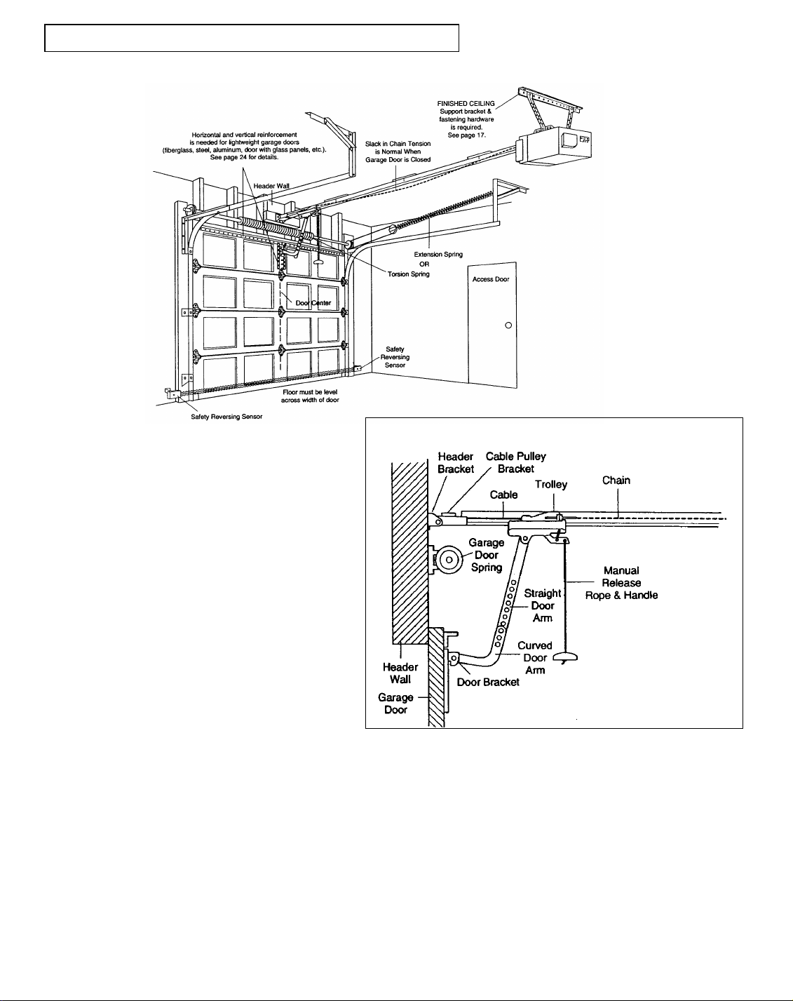
SECTIONAL Door Installation
Before you begin, survey your garage area to see whether any of the conditions below apply to your installation.
Based on your particular requirements, there are
several installation steps which might call for
materials and/or hardware not included in the
carton.
• Step 1, page 12 - Look at the wall or ceiling
above the garage door. The header bracket
must be securely fastened to structural
supports.
• Step, 5 page 17 - Do you have a finished
ceiling in your garage? If so, a support
bracket and additional fastening hardware
may be required.
• Safety reversing sensor, page 21 -
Depending upon garage construction, wood
blocks may need to be fastened to mounting
locations before sensors are installed.
• Step 10, page 22 - Alternate floor mounting
of the safety reversing sensor will require
hardware not provided.
• Step 11, page 24-Do you have a steel,
aluminum, fiberglass or glass panel door? If
so, horizontal and vertical reinforcement is
required.
• Look at the garage door where it meets the
floor. it must close on the floor all the way
across. Otherwise, the safety reverse system
may not work properly. See page 30. Floor or
door should be repaired.
• If your door is more than 7 feet, see the
longer rails available on page 38.
• The opener can be installed within 2 feet to the left or
right of the door center if there is a torsion spring or
center bearing plate in the way of the header bracket or
door bracket area. If your door has extension springs,
the opener must be installed in the center of the door.
See pages 12 and 24.
• Do you have an access door in addition to the garage
door? If not, Model 7702CB Outside Quick Release is
required. See page 38.
You may find it helpful to refer back to this page as
you proceed with the installation of your opener.
4
Closed Position

ONE PIECE Door Installation One Piece Door without Track
Before you begin, survey your garage
area to see whether any of the
conditions below apply to your
installation.
Based on your particular requirements, there are several
installation steps which might call for materials and/or
hardware not included in the carton.
• Step 1, page 13-Look at the wall or ceiling above the
garage door, The header bracket must be securely fastened
to structural supports.
• Step 5, page 17- Do you have a finished ceiling in your
garage? I so, a support bracket and additional fastening
hardware (not supplied) may be required.
• Safety reversing sensor, page 21-Depending on garage
construction, wood blocks may need to be securely
fastened to mounting locations before sensors are installed.
• Step 10, page 22- Alternate floor mounting of the safety
reversing sensor will require hardware that is not provided.
• Step11, page 25-Generally, a one -piece door does not
require reinforcement. If your door is lightweight , you can
refer to the information relating to sectional doors on page
24.
• Step 11, page 25-Depending on your door’s construction,
you might need additional mounting hardware for the door
bracket.
• Do you have an access door in addition to the garage door?
If not, Model 7702CB Outside Quick Release is required.
See page 38.
• The gap between the bottom of the garage door and the
floor cannot exceed 1/4”. Otherwise, the safety reverse
system may not work properly. See page 30. The floor or
the door should be repaired.
You may find it helpful to refer back to this page as
you proceed with the installation of your opener.
5

OPENER CARTON INVENTORY
Your garage door opener is packaged in one carton which contains all parts illustrated below. If anything is
missing, carefully check the packing material. Parts may be “stuck” in the foam. Hardware for assembly and
installation is shown on page 7.
6
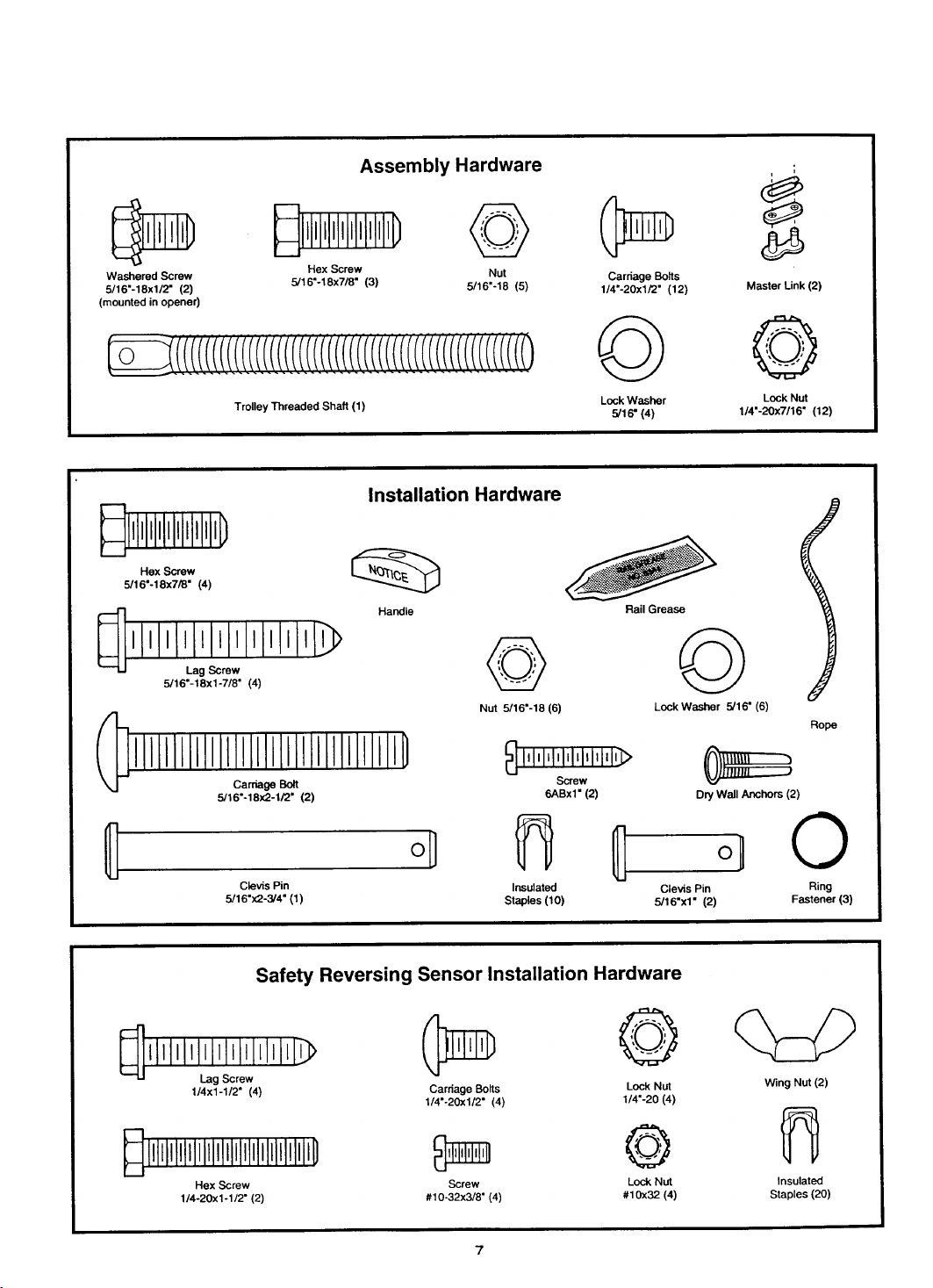
Separate all hardware from the pakages in the rail carton and the opener
carton, as shown below, for assembly and installation procedures.
7

Assembly Section: Pages 8-11
To avoid installation difficulties, do not run the garage door opener until instructed to do
so.
Assembly Step 1
Assemble the T-rail & Attach
the Cable Pulley Bracket
• Align the 4-rail sections on a flat surface
exactly as shown. Center sections are
interchangeable for ease of assembly.
• Insert the carriage bolts so the square bolt
necks seat in the square holes in the T-
rail sections and pass through the round
holes in the rail braces. Assemble lock
nuts, ensure alignment and tighten.
If T-rail is not assembled exactly as
shown, trolley will not travel
smoothly along length of rail or it
will hit against the nuts.
Make sure bolt
necks are seated in
the square holes
and rails are
aligned before you
tighten lock nuts.
(See right and
wrong
views).Improper
assembly can
cause jerky trolley
operation, noise
and/or nuisance
door reversals.
• Position the cable pulley on the front
end of the T-rail as shown. Fasten
securely with the hardware shown.
When tightening the
screws, be sure to
keep bracket parallel
to the rail. Otherwise,
the rail may bow when
the opener is
operated.
8

Assembly Step 2
Install the Trolley on the T-rail
Assembly Step 3
Fasten the T-rail to the Opener
• Place the opener on packing material to protect
the cover. For convenience, put a support under
the cable pulley bracket.
• Remove the (2) 5/16”-18x1/2” washered screws
mounted in the top of the opener.
• Align the holes in the back section of the T-rail
with the holes in the opener.
Fasten the rail with the (2) washered screws
previously removed. Tighten securely.
Remember to use only these screws! Any
other screws will cause serious damage to the
opener.
• Insert a 5/16”-18x7/8” hex screw into the trolley
stop hole in the T-rail as shown. tighten securely
with a 5/16” lock washer and nut. This screw
limits trolley travel in the Up direction.
CAUTION
Use only those screws mounted in
the top of the opener. Any other
screws will cause serious damage to
the opener.
9
• As a temporary stop, insert a
screwdriver into the hole in the
front end of the T-rail.
• Slide the trolley assembly along
the rail to the screwdriver stop.
•
If trolley hits against the nut on
the T-rail, the bolts and nuts
were attacked from the wrong
side and must be repositioned.
Review Step 1.

Assembly Step 4
Install the Chain/cable & Attach
the Sprocket Cover
Master Link Procedure
Push pins of master link bar
through cable loop and hole in
front end of trolley. Push cap over
pins and into notches. Slide clip-on
spring over cap and into notches
until both pins are securely locked.
To attach the sprocket cover:
• Insert the back tab in the opener slot. Squeeze the
cover slightly and insert the front tab in the slot on the
mounting plate.
• Detach the cable loop from the carton and
fasten it to the trolley with a master link from
the hardware bag. See master link
procedure, Figure 1.
• With the trolley against the screwdriver,
dispense the cable around the pulley.
• Proceed back around the opener sprocket,
Figure 2. Be sure sprocket teeth engage the
chain. Continue forward to the trolley
threaded shaft, Figure 3.
•• Use the second master link to connect the
chain to the flat end of the shaft. Check to
make sure the chain is not twisted.
• Remove the screwdriver.
Figure 1
10
This manual suits for next models
2
Table of contents
Popular Garage Door Opener manuals by other brands


Craftsman
Craftsman 139.53924 owner's manual

Chamberlain
Chamberlain MyQ 940ESTD owner's manual

Automatic Technology
Automatic Technology GDO-9V1 SecuraLift installation instructions

Westfalia
Westfalia 19 36 07 instruction manual

Chamberlain
Chamberlain HD520EVP manual

Cardin
Cardin BL Series instruction manual