Fredenstein HD Reference User manual

HD
REFERENCE
Operating Manual

Fredenstein HD Reference Preamplifier
The Fredenstein HD Reference microphone preamplifier utilizes a completely new approach to
microphone level amplification. Many in the recording industry are now using 96 Hz or 192 Hz
sampling rates while trac ing, but still using equipment, which cannot provide the frequency
response or bandwidth provided by modern A/D converters. The HD Reference overcomes these
limitations and yields a new sound quality. Especially for wider bandwidth sources, li e acoustic
instruments, voices, and drums, the HD Reference is simply unequaled. It is the preferred choice
for classical recordings as well.
The HD Reference was preceded by the HD Pre which was designed for the 500 Series rac s, but
that format does have limits regarding available voltage and current plus imposes some restraints on
the available physical area. Never the less, the HD Pre set new levels of performance in all of the
important parameters pertaining to mic pre-amplifiers. The HD Reference surpasses the HD Pre due
to higher voltage power supplies +/-24V rather than +/- 16V, higher current (?? vs +/- 150mA), and
even more discrete transistors (from 54 in the HD Pre to 64 in the HD Reference).
The HD Reference also goes a step further by allowing a full featured Remote Control called The
Commander that can access every function on the front panel. The HD Reference and Commander
are connected with a conventional XLR cable, that can be routed though a patch bay if necessary.
With 920 Hz bandwidth available, it ma es little sense to ris losing that fidelity with a mic driving
100 feet or more of mic cable. With the HD Reference placed close to the microphones and short
mic cables in use, the engineer can realize the benefit of bandwidth.
The HD Reference also has a few added features, such as a display that shows gain in dB next to the
nob that allows one to set gain in accurate 1dB steps, which is great for setting up stereo pairs. We
also added more choices to the High Pass Filter (Off, 39Hz, 82Hz) and more choices to the Input
Impedance (200K, 1K, 300, 232).
In terms relating to audibility, the HD Reference is very very fast, clean and true to the source, with
very low noise. And for the technically inclined, it does this without negative feedbac and,
maintains outstanding performance at any and all gain settings, which is rare indeed.
Besides incorporating a fully discrete signal path and a Class-A balanced output stage, the HD
Reference uses a revolutionary current amplification circuit, which neutralizes internal transistor
capacitance (Miller Effect) that limit frequency response and slew rate in conventional voltage
amplifiers. As a result, the HD Reference features an unprecedented bandwidth of over 900 Hz.
The HD Reference may also be unique in the world of mic pre-amps in needing moderate sized heat
sin s that one might expect to see in a small power amp. The output stage is also really Class A,
running on 48 volts and can drive +29 dBm (60 volts pea to pea ). And this implies appreciable
idle current, and some heat generated.. No problem driving long lines and still sounding fine
though, than s to that available current...
The HD Reference does not use input or output transformers. These would prevent the pre-amp
from having the amazing specifications and performance that it is capable of. The F601A Mic Pre
has both an input transformer and output transformer that can be inserted or bypassed. The F609,
F676, F200, V.A.S and Artistic Mic Pre's all have transformers and each has special applications in
where they excel and compete with well nown vintage pieces.
Fredenstein HD Reference Manual V1.0 Feb 5, 2016 Page 1

Fredenstein HD Reference Preamplifier
Installation:
Electrical Safety arnings:
Do not open the enclosure, hazardous voltages are present inside!
There are no user serviceable parts inside.
Refer servicing to qualified personnel.
Do not expose this appliance to rain and moisture.
Do not block any ventilation openings. Do not install near heat sources.
Protect the power cord from being walked on or pinched. Do not defeat the
safety purpose of the polarized or grounding plug and connect to a properly
grounded mains socket.
According to EEE Directive (2012/19/EU) this product must not be disposed
with household waste. This product should be taken to a licensed EEE collection
center for recycling.
If you need to replace the mains fuse, make sure the replacement has the same
rating , 2AT 250V, slow blow (2 Amp) in the IEC socket on the HD Reference.
If you need to replace the mains fuse, make sure the replacement has the same
rating , 1AT 250V, slow blow (1 Amp) in the IEC socket on the Commander.
The HD Reference does get hot. This is a result of it using 4 Class A amplifiers
on 48 Volt rails, which, in terms of heat generated, is like having a 15 watt light
bulb in a 1U box.
Please provide for some space directly above and below for ventilation.
Fredenstein HD Reference Manual V1.0 Feb 5, 2016 Page 2

Fredenstein HD Reference Preamplifier
The input impedance of the HD Reference is natively 200 Ohms (200,000 Ohms) and can be
reduced to 1KOhm (1000 ohms) or 300 Ohms by activating the LOW-Z functions. With both 1K
and 300 pressed, the input impedance is approximately 230 Ohms. The initial 200 Ohm input
impedance avoids loading the microphone output transformers and yields, in some cases, sonically
superior results. The lower impedance settings tend to increase the damping of dynamic and ribbon
microphones. We suggest that while you are learning this preamp, that you listen while changing
impedance settings. What to listen for, you as ? Passive microphones such as dynamics and ribbon
mics may sound tighter, snappier, dryer or more direct with lower impedance settings, but on the
other hand, you may be more accustomed to those mics sounding a certain way and that is why you
chose to use them, so in those cases probably the higher impedance settings may sound more
familiar. Consider the artistic possibilities and the new flavors you can get from your mic collection.
With some microphones, the transformer inside them comes into play because they may be
optimized for a particular range of impedance's. In those cases, it is li ely that either the 1K or
200K settings may be most appropriate. Generally this translates to differences in the high
frequency response and the “brightness” and the quality of the sibilance (“natural” is usually
preferred). Lastly, some active microphones might conceivably distort a little prematurely into the
300 ohm setting,. On the other hand, consider that most active mics are designed so that the capsule
should distort from sheer SPL first, and there is at least a few dB headroom in the electronics
beyond that, so that scenario is unli ely. In any case, the engineer can switch between the settings to
find the desired result without any fear of damaging the microphone.
Just to complicate matters, the length and capacitance and quality of the microphone cable may be
the biggest factor for the microphone and its transformer to deal with. This too represents an
impedance that the mic needs to drive, and this is an impedance that becomes lower at high
frequencies. For example, a long cable might reduce the benefit of the 200K setting. A typical 10
meter cable capacitance may reduce the impedance to 10 Ohms at 10 Hz and 5 Ohms at 20 Hz.
Phantom powered output amplifiers of microphones do not have a lot of voltage or current to wor
with and is part of the reason why using the HD Reference to drive the long line is preferred.
Another reason is that a line level signal is more immune to RF and interference than a much lower
level mic level signal. Sometimes corrosion on XLR connectors can cause a “diode effect” that can
bloc a low level signal, but a larger signal may clear the bloc age, and of course that is a
simplified description, but hints at one more reason where a remote controlled mic-pre may be an
advantage.
One final note regarding the HD Reference input impedance. Li e virtually all mic pre's that
include Phantom Power, a pair of 6.8 Ohm resistors are bridged across the input to feed enough
current to power the microphone. In the HD Reference, these resistors are removed from the circuit
when Phantom Power is not required, which ma es possible the unusually high 200 Ohm setting.
However, when Phantom Power is needed then the maximum impedance is lowered to about 13
Ohms, due to those resistors, but it is still a high impedance by mic-pre standards. Phantom power
also lowers the 1K and 300 Ohm settings but proportionately much less.
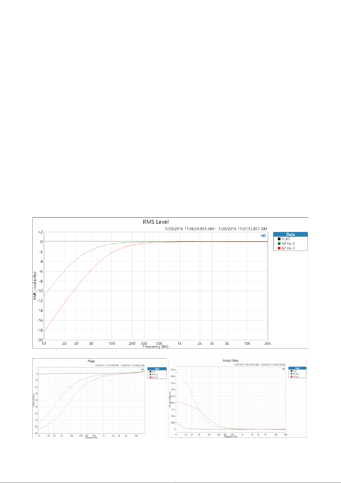
The HD Reference includes a high pass filter or low cut filter with 2 select-able frequencies, 39 Hz
and 82 Hz. The filter is before any active electronics and can certainly help reducing pops and
plosives when used for vocals, but we might suggest that physical pop filters or angling the mic
Fredenstein HD Reference Manual V1.0 Feb 5, 2016 Page 3
Fredenstein HD Reference Preamplifier
when possible. The most common use for high pass filters is to reduce unwanted rumble from air
conditioners or from outside sounds when acoustic isolation tends to be be less than perfect.
High pass filters can also help reduce lea age from other sources when the the instrument has
minimal low frequency information, and the lea age mostly exists as low frequencies. Sometimes,
we use high pass filters to sculpt the sound and clear some space for other instruments, but this
technique is probably better done in the mix and better done with flexible or specifically chosen
filters. It is just safer, because once one filters out the lows, they are gone permanently. The
microphone's high pass filter and most mic-pre's high pass filter, were probably never intended to be
an artistic EQ, but were intended to be simple problem solvers.
We might characterize the high pass filters in the HD Reference as relatively gentle and safe. The
filters are 6 dB/oct types with minimal phase shift and low group delay distortion. Steep filters tend
to introduce more phase shift which basically means the low frequencies may arrive milliseconds
later than mid frequencies. This can be less than ideal with percussive instruments li e drums unless
the object was to lessen the impact and realism. But steep low pass filters can be more effective at
removing garbage below a certain frequency. For the HD Reference, the filters were chosen with
the idea that users would use a pre-amp of this quality to record in better spaces and that the HD
Reference would be a natural choice for percussion instruments li e drums and piano. In fact, with
the right mic, it may well be the first choice with any acoustic instrument that is intended to invo e
realism or sound natural.
Fredenstein HD Reference Manual V1.0 Feb 5, 2016 Page 4

Fredenstein HD Reference Preamplifier
Unfortunately, standard audio test equipment is unable to cover the complete range of the HD
Reference. The frequency response of the HD: 10Hz to 50 Hz within 0.1 dB at ALL gain settings,
-3dB at 2Hz and 900 Hz. At most gain settings, it becomes even flatter.
Figure 1: Frequency response. At first glance, it may loo li e the HD Reference is down 13-16 dB
at 2 Hz, which might not be so bad because the graphs are still dead flat at 10 Hz, but there are 3
lines virtually on top of each other and one is the graph of the Audio Precision APx515 measuring
itself. Only the +60 dB gain setting (red line) shows any visual departure from the others (-0.5 dB at
5 Hz, -2.5 dB at 2Hz). With 40 dB gain, you can see the HD Reference measured as flat as the AP
within 0.1 dB from 2 Hz to 80 Hz, which were the frequency limits of the AP. Actually it stays
very flat to about 10 times that. Even 10 Hz and 100 Hz square waves still loo respectably square.
Figure 1
Figure 2: Noise floor at 64 dB gain. The most remar able quality in this graph is the flatness. All
amplifiers are guilty of 1/F noise which shows up as increased noise at low frequencies. The 1/F
noise corner of the HD Reference is typically 10Hz which ran s among the best. Very flat HF too.
Fredenstein HD Reference Manual V1.0 Feb 5, 2016 Page 5

Fredenstein HD Reference Preamplifier
Figure 2
Figure 3: Total Harmonic Distortion. This graph shows the 1 Hz THD as the input signal is
stepped over a 86 dB range. Two gain settings are shown, 0 dB and +40 dB. Even with 40 dB of
gain, distortion is typically near -100 dB which translates to 0.001%. You can see a smooth gradual
climb after the output passes +5 dBu on the +40 dB gain setting.
Figure 3
Figure 4: THD&N Ratio.
Changing the measurement to “percentage” and allowing for “noise”. With the noise floor, the
actual THD&N becomes 0.003% near +10 dBu for the 40 dB gain setting, and 0.001% near +15
dBu output level for the 0 dB setting. The rising slope towards the left simply shows that when the
input signal is very low, that the noise floor represents a relatively a larger percentage of the output.
We can point out, that if you compare other graphs of this type, most show a lowest point between
+20 dBu and +25 dBu, then rise suddenly and sharply as the device nears hard clipping. Notice the
gentle rise in the HD Reference. Tube circuits also often tend to have this ind of curve.
Fredenstein HD Reference Manual V1.0 Feb 5, 2016 Page 6
Fredenstein HD Reference Preamplifier
Figure 4
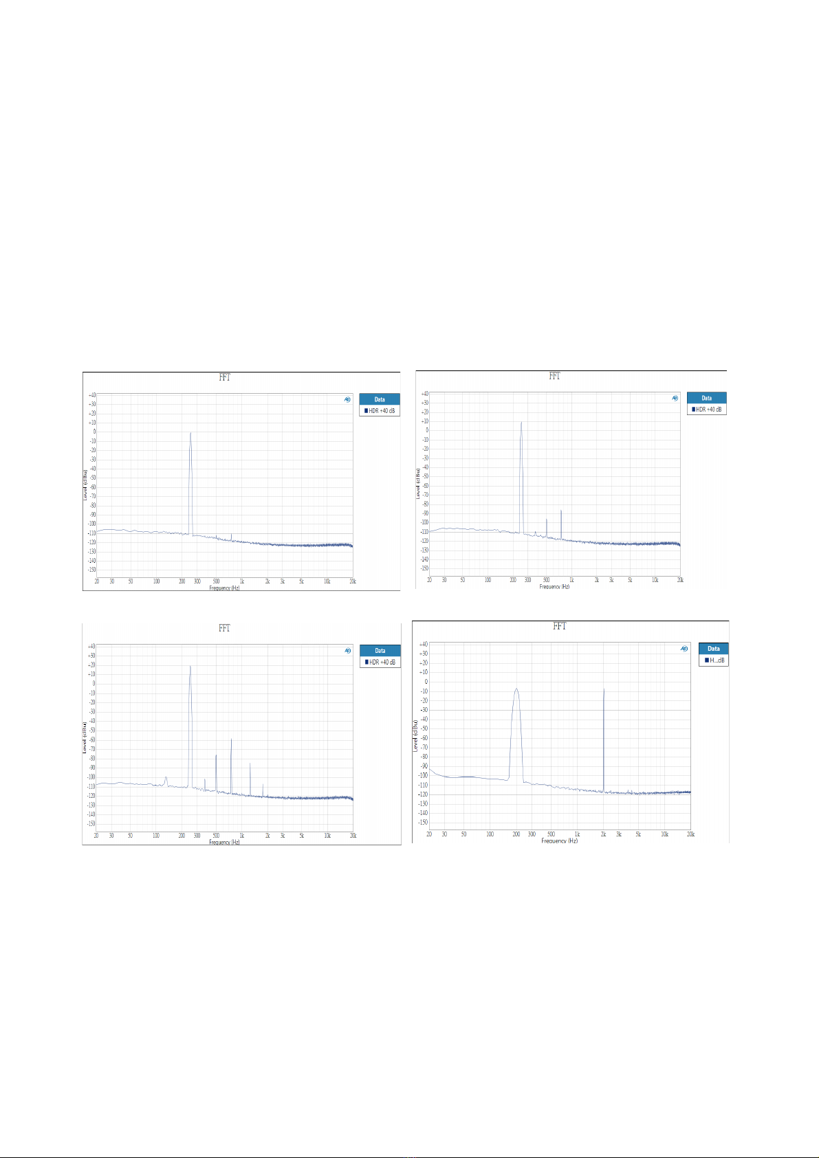
Figures 5, 6, 7 show the harmonic levels at various output levels with the 40 dB gain setting and a
250 Hz input (chosen for a centered graph). Figure 4 at 0 dBu output, Figure 5 at +10 dBu output,
Figure 6 at +20 dBu output which is near where many A to D converters overload. Notice 2nd
harmonic at 500 Hz and 3rd at 750 Hz and nothing above 7th. Tube circuits often display similar
harmonic signatures. The idea that tubes only generate even harmonics and solid state generates odd
harmonics is just a myth. It all depends on how they are biased. Most properly designed tube
circuits show similar amounts of 2nd and 3rd below clipping, often somewhat more 3rd. Similarly,
transformers usually display mostly 3rd and 5th harmonics at low frequencies and high levels, but are
sometimes biased them to bring in some 2nd. These graphs show a nice onset and harmonic balance.
Figure 8 shows two tones, 200 and 2 Hz, at 0 dBu input (each at -6 dB), to illustrate the virtually
invisible IM distortion at that level.
Figure 5 Figure 6
Figure 7 Figure 8
OK, that is enough of gee y graphs, but sometimes a picture is worth a thousand words. Even
though the frequency response goes amazingly high, don't expect that the HD Reference will be
“bright” because the frequency response is also very flat, but it may be brighter than a preamp with
a rolled off top end. Also, while you can get some pleasant color and character from this pre, it
depends on how hot the output is driven, and it may be subtle, depending on the source or
instrument. It wasn't designed to have a dramatic heavy signature sound and it certainly isn't a fuzz-
box. You can also see how at lower levels it becomes super clean.
Fredenstein HD Reference Manual V1.0 Feb 5, 2016 Page 7

Fredenstein HD Reference Preamplifier
Controls and Operation:
Rotary Control:
GAIN : Gain Control from
0 to 64 dB in 1dB steps
Pressing the Gain Knob Mutes the output and the Gain Display Blin s
Output Peak Level Indicator: -18dB to +20 dB, 2 dB steps (0dB = +4dBu)
Switches:
P48 : +48 Volt Phantom Power when lit
POL : Reverse Output Polarity when lit
LO Z 300 300 Ohms Input Impedance when lit
LO Z 1K : 1000 Ohms Input Impedance when lit
With neither 1K and 300 pressed, the input impedance is approximately 200 Kohms
Note: With P48 engaged 200K becomes approximately 13 Kohms.
Low Cut 39 : reduces the lower frequency response to 39 Hz
Low Cut 82 : reduces the lower frequency response to 82 Hz
Fredenstein HD Reference Manual V1.0 Feb 5, 2016 Page 8

Fredenstein HD Reference Preamplifier
Gain Control:
Rotary Encoder sets the Gain in 1 dB steps which are displayed next to the nob. Pushing the Knob
activates an immediate MUTE. This control as with all others can be remote controlled
POL – Polarity Control:
Pushing the POL switch selects the polarity, when lit (blue), the output polarity is reversed.
Otherwise the true, non-reversed, polarity is selected (normal operation).
Low Z 1K – Low Input Impedance:
When lit (green), the input impedance changes from 200 Ohms to 1000 Ohms. Some dynamic-
and ribbon-microphones are most linear driving a low input impedance.
Low Z 300 – Low Input Impedance:
When lit (green), the input impedance changes from 200 Ohms to 300 Ohms.
P48 Phantom Power:
Most FET condenser microphones as well as some other microphones with built-in amplifiers
require +48V Phantom Power. Setting the P48 switch (red light) enables +48V through the balanced
microphone line. Please chec your microphone documentation if you are not 100% sure. Enabling
P48 on microphones not designed for P48 might cause severe damage to the microphone. The DI
input is not supplied with Phantom Power.
Low Cut 39Hz:
A 39 Hz low cut filter is activated when lit, avoiding unwanted low frequencies while trac ing.
Low Cut 82Hz:
A 82 Hz low cut filter is activated when lit, avoiding unwanted low frequencies while trac ing.
DI – Direct Input:
The most common use for the DI input is to connect instruments li e guitars directly to the HD
Reference. The input impedance is greater than 2 MOhms to insure compatibility with most
instrument pic ups. After inserting a balanced (Tip-Ring-Sleeve) or an unbalanced (Tip-Sleeve)
plug, the balanced microphone input through the box or rac is automatically disabled.
The Gain range for the DI is from 0 to +40. Turning the Gain nob past +40 will have no effect.
When a 1/4” plug is inserted into the DI jac , the HD Reference automatically switches in the DI
pre-amplifier and lights up a LED at the bottom right of the Gain Display. If a Commander is used it
will also use that LED to display that the DI is plugged in
There is also an indicator called LOCK STATUS, which lights up if the LOCK button is pushed on
the Commander. If this is lit, all controls on the HD Reference are frozen and can only be controlled
from the Commander. This is to prevent tampering.
Fredenstein HD Reference Manual V1.0 Feb 5, 2016 Page 9
Table of contents
Other Fredenstein Amplifier manuals

Fredenstein
Fredenstein Artistic MicPre Plus User manual

Fredenstein
Fredenstein Artistic Microphone Preamplifier SE User manual

Fredenstein
Fredenstein ramDI User manual

Fredenstein
Fredenstein F605 User manual

Fredenstein
Fredenstein MAGIC PRE User manual

Fredenstein
Fredenstein F660A User manual

Fredenstein
Fredenstein F609 TUBE User manual

Fredenstein
Fredenstein F676 User manual

Fredenstein
Fredenstein F660 User manual

Fredenstein
Fredenstein F200 User manual


