10 7
MAINTENANCE AND TROUBLESHOOTING
For optimal performance of the strength equipment and to reduce the chances of injury to users, you must per-
form preventive maintenance on a regular basis. Instruct all personnel to perform the procedures described in
this section. Personnel must also record and report any accident. To maintain the strength equipment’s warran-
ty, use only FREEMOTION EPIC parts for repair or replacement. If there are any questions or concerns, see
HOW TO CONTACT CUSTOMER CARE on the back cover of this manual.
DAILY MAINTENANCE
Upholstery and Frame—General Cleaning
1. Clean the strength equipment using a soft cloth
dampened with a light solution of mild soap and
warm water. If necessary, use a soft bristle brush
with the cleaning solution.
2. Rinse the area thoroughly using a soft cloth damp-
ened with clean water and dry thoroughly.
Upholstery—Difficult Stains
1. Spray the stain with a non-abrasive household
cleaner such as FORMULA 409®cleaner, SIMPLE
GREEN®,or a similar product. Rub the stained
area gently and let the cleaning solution sit for a
few minutes.
2. Rinse the area thoroughly using a soft cloth damp-
ened with clean water and dry thoroughly.
3. Repeat these steps if necessary using a soft bristle
brush.
Optional Method for Difficult Stains
1. Rub the stained area gently using a soft cloth
dampened with rubbing alcohol.
2. Rinse the area thoroughly using a soft cloth damp-
ened with clean water and dry thoroughly.
CAUTION: When using any cleaning product, try it
first in an unnoticeable place to ensure that there is no
damage to the material. Follow the directions and the
safety precautions of the manufacturer of each clean-
ing product used. FreeMotion Fitness and its vendors
cannot be held liable for damage or injuries resulting
from the use or misuse of cleaning products.
Important: Do not use abrasive cleaners, which may
scratch the strength equipment. Strong cleaners and
abrasives will damage decals; use caution around
decals. Do not use solvents such as lacquer thinner,
kerosene, gasoline, or similar liquids.
WEEKLY MAINTENANCE
Hardware
Check all nuts and bolts and tighten them as required.
Important: All FREEMOTION EPIC cushions have
dense plywood supports with tee-nuts that are used to
bolt the cushions to the strength equipment. Because
the tee-nuts are held by the plywood, they will not
withstand the torque that standard nuts and bolts will.
When tightening the bolts securing a cushion, turn
them only until they are snug and the cushion does
not move or feel loose. Overtightening may strip the
tee-nuts from the plywood and make it impossible to
remove the cushion in the future.
Cables
1. Check each cable for proper tension (see CABLE
ADJUSTMENT on page 8).
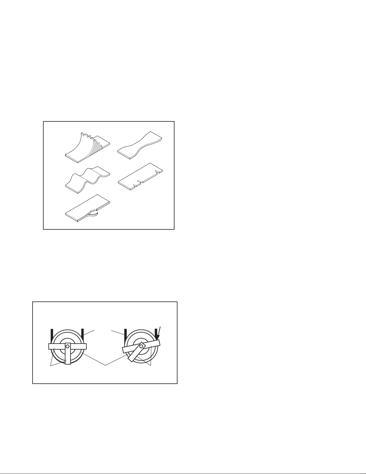
2. Check the entire length of each cable by slowly
performing one repetition on the strength equip-
ment; inspect the cable that is exposed on the
exterior of the strength equipment and the cable
inside the tower. Run your fingers along the cable,
paying close attention at the bends and attachment
points. Watch for the following conditions, which
may indicate a worn cable in need of replacement:
A. atorn or split cable sheath that exposes the
cable
B. a kinked or severely bent cable
C. a curled or twisted sheath
D. a stretched cable sheath, showing a thinning
cross-section
WEIGHT STACK SERVICING
Servicing the weight stack involves replacing the two
guide bushings and weight insert in the top weight. To
order these parts, see HOW TO CONTACT CUS-
TOMER CARE on the back cover of this manual.
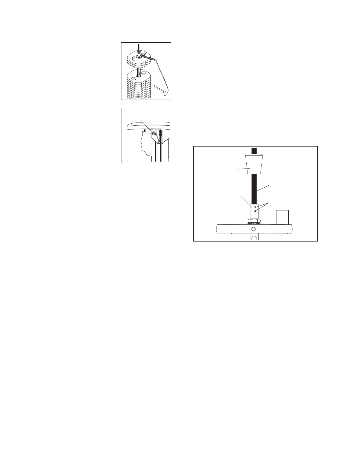
1. Remove the wingnuts under the tower cap and
remove the tower cap from the tower.
2. Remove the guide rod nuts and washers from the
top of each guide rod.
3. Lift the coupler cover and loosen the four set
screws—this will release the cable.
4. Lift the guide rods out of the top of the tower.
5. Remove the rod nut, rod star washer, and rod
washer from the top of the weight rod. Lift and
rotate the top weight, and remove it through the
front opening of the tower.
6. Use a punch to drive the two existing guide bush-
ings and the weight insert out of the top weight.
7. Hold one of the new guide bushings square to the
face of one of the holes in the top weight, place a
protective piece of wood on top of the guide bush-
ing, and lightly tap the guide bushing until it is flush
with the surface. Insert the other guide bushing
and the weight insert in the same way.
8. Replace the top weight. Next, tighten the rod nut,
rod star washer, and rod washer onto the weight
rod.
9. Reattach the cable to the top weight coupler.
Retighten the four set screws into the threaded
holes. Tighten the set screws equally until they
contact the cable. Then, tighten each screw alter-
nately 1/4 turn, until all are set to 150 inch/pounds
(17 Newton-meters).
10. Clean and lubricate the guide rods by wiping them
with a soft cloth containing a lightweight motor oil,
10W-40 or 10W-30 weight. Apply only a light coating
over the entire length. Do not use TEFLON®or sili-
cone-based lubricants.
11. Reinsert the guide rods through the top of the tower
and into the weight stack. Note: If the weight stack
has shifted, use a short bar to realign the holes in
the weight plates. Hold the weight plates while
inserting the guide rods.
12. Reattach the guide rods to the top of the frame with
the two guide rod nuts and washers.
13. Insert the weight pin into the top weight. Slowly per-
form a repetition, lifting the top weight as far as
possible. Then, slowly lower the top weight. If the
top weight sticks, loosen one of the guide rod nuts.
Slowly perform another repetition. Retighten the
guide rod nut. Check the full travel again and read-
just the guide rod nuts as necessary.
14. Slowly perform a repetition using a light load and
have someone make sure that the cable is not
derailed from a pulley or rubbing on a cable
guard.
15. Replace the tower cap and retighten the wingnuts
onto the bolts.
Weight
Insert
Guide
Bushing
Guide
Bushing
Top Weight
Top Weight
Coupler
WARNING: Do not force the
guide rods into the weights; doing so will
damage the bushings and weight inserts.
A
B
D
C