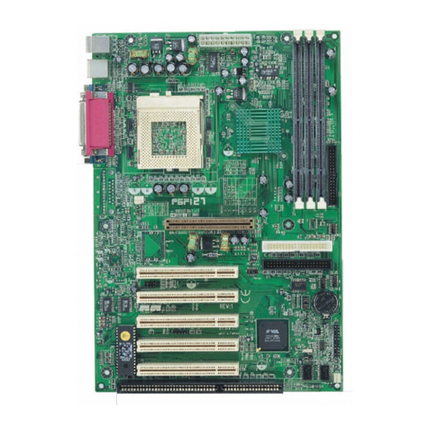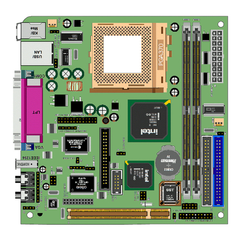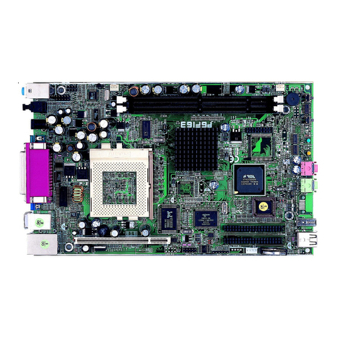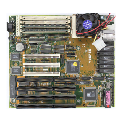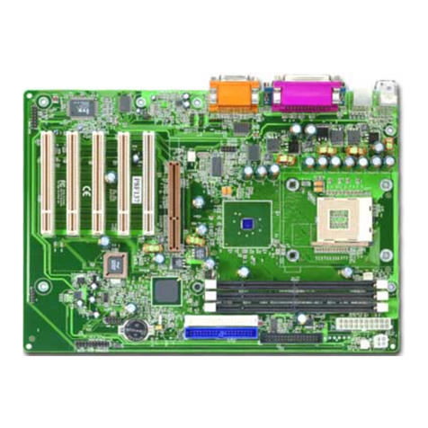
1. Mainboard Layout:
2. Jumpers & Connectors: 3. DIMM Memory Configuration
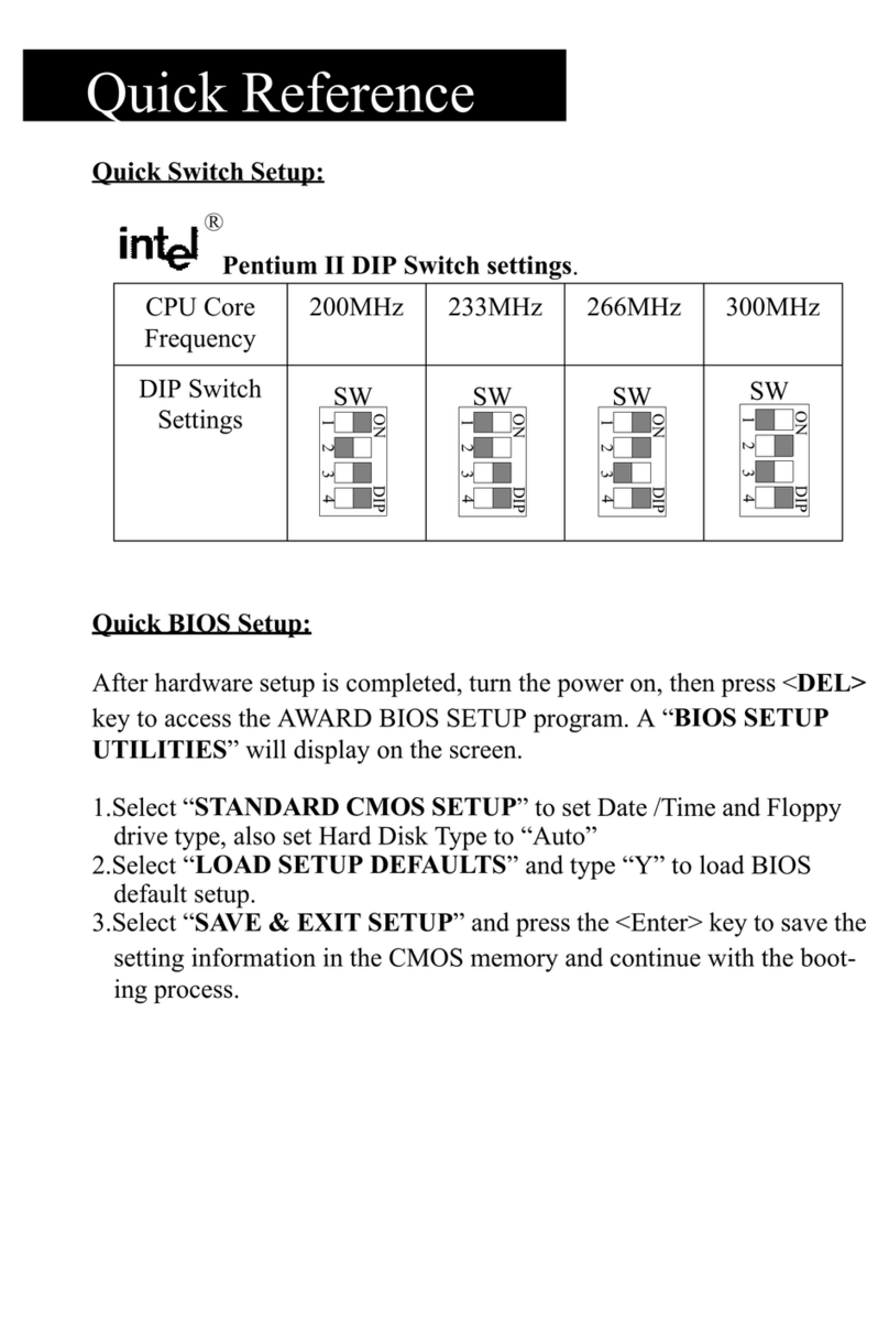
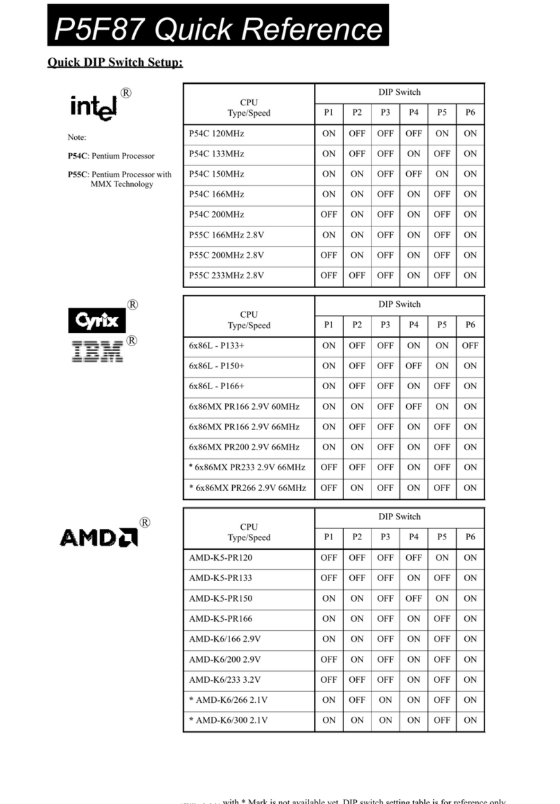
4.CPU Core to Bus Clock Multiplier
DIP Switch (SW1) selects Bus Clock Multiplier
BANK 0 (DIMM1) EDO/SDRAM 4, 8, 16, 32, 64, 128, 256MB
BANK 1 (DIMM2) EDO/SDRAM 4, 8, 16, 32, 64, 128, 256MB
BANK 2 (DIMM3) EDO/SDRAM 4, 8, 16, 32, 64, 128, 256MB
Total
System Memory 8MB to Max. 768MB
Multiplier SW2-P4 SW2-P5 SW2-P6
x 2.0 OFF OFF ON
x 2.5 OFF ON ON
x 3.0 OFF ON OFF
x 3.5 OFF OFF OFF
x 4.0 ON OFF ON
x 4.5 ON ON ON
x 5.0 ON ON OFF
x 5.5 ON OFF OFF
1 2 4 5 7 8 1011
12131415 1819202122
Jumpers: JP7: 1-2 Normal Mode
2-3 Clear CMOS RAM
Front Panel Connector
HDD
LED STB
LED RESET PW_SW
SPEAKER PW LED&KEYLOCK
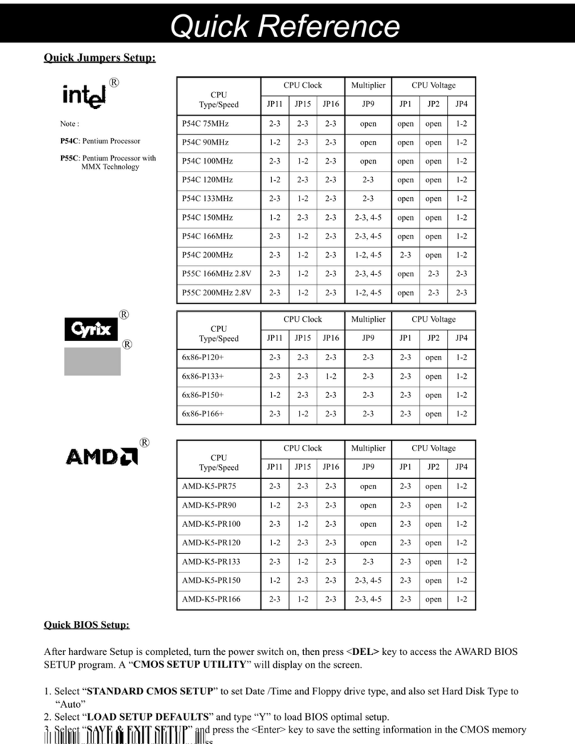
P5F103 Quick Reference
The User’s Manual is located at Compact Disc’s \manual\English or Chinese
CPU Voltage 2.0V 2.1V 2.2V 2.3V 2.4V 2.5V 2.6V 2.7V 2.8V 2.9V 3.0V 3.1V 3.2V 3.3V 3.4V 3.5V
SW2-P1 OFF ON OFF ON OFF ON OFF ON OFF ON OFF ON OFF ON OFF ON
SW2-P2 OFF OFF ON ON OFF OFF ON ON OFF OFF ON ON OFF OFF ON ON
SW2-P3 OFF OFF OFF OFF ON ON ON ON OFF OFF OFF OFF ON ON ON ON
5. CPU Bus Clock (The CPU input clock)
ALi Aladdin V chipset can only support CPU Bus Clock up to 100MHz.
However, the clock generator of the P5F103 motherboard allows user to
change CPU Bus Clock from 60to120MHz. Over clock (105~120MHz)
may cause system intermittent lock up or fail to boot-up (no video).
times the “CPU Core to Bus Clock Multiplier”.
The CPU internal core clock is equal to the “CPU Bus Clock”
6. CPU Core and I/O Voltages
Two voltages Vcore and VI/o are required for Pentium class CPUs. The Vcore is used for CPU internal operation and
the VI/o is used to supply the voltage for external interface. The P5F103 motherboard has a jumper (JP2) which
connect between Vcore and VI/o. You need to short JP2 only when a Intel Pentium O.D.P. is installed.
DIP Switch (SW1) selects CPU Bus Clock
Bus Clock SW2-P1 SW2-P2 SW2-P3 JP13
60MHz ON ON ON Open
66MHz (default) ON ON OFF Open
68MHz ON OFF ON Open
75MHz OFF ON ON Open
83MHz OFF ON OFF Open
95MHz OFF OFF ON Open
100MHz OFF OFF OFF Open
105MHz ON OFF OFF Close
110MHz ON OFF ON Close
115MHz ON ON OFF Close
120MHz ON ON ON Close
82443EX
1
1
1
BANK 0
DIMM3
DIMM2
ESS
AudioDrive
ES1898
Socket 7
ON
1 2 3 4
DIP
5 6
SW2
ON
1 2 3
DIP
SW1
ALi
M1541
ALi
M1543
BANK 2
BANK 1
WOL
1
JP11
JP13
JP14
CD1
CD2
MD1
MD2
IR
1
DIMM1
FAN
1
17
21
5
6714
8
10
11
15
20
4
12
9
19
18 16
13
2222
JP7
23
1: CPU Socket
2: ISA Expansion Slots
3: PCI Expansion Slots
6: IDE Connectors
5: DIMM Module Sockets
8: Parallel Port Connector (T)
7: Floppy Drive Connector
4: AGP Slot
Serial Port Connectors (B)
PS/2 Keyboard Connector (B)
12: Flash BIOS
13: Switching Regulator
14: Front panel Connectors
15: Battery (CR2032 Lithium)
9: IR Port Header
10: ATX Power Connector
11: PS/2 Mouse Connector (T)
16: Dual USB Connector
17: CPU FAN Connector
18: System Monitor W83781D(optional)
19: Wake On LAN Header
20: Game/MIDI Port (T)
21: Voice Modem Connector
22: L2 Cache (Data Cache)
Audio MIC/IN/OUT (B)
