freightliner Park Smart Manual

1
Technical Information and Diagnostic Guide
FOR
Freightliner Park Smart No Idle System
This guide will assist you in becoming more familiar with the working components of
the Park Smart® System and the proper steps and procedures to completely diagnose
the no idle unit.

2
Table of Contents
1) External Component Identification and Location
Page
A: Battery Separator ..........................................................4
B: F1 Fuse 60 amp (Maxi)..................................................4
C: F2 Fuse 15 amp (Mini) ..................................................4
D: F3 Fuse 20 amp (Mini) ................................................4
E: F4 Fuse 50 Amp (Maxi).................................................4
F: F5 Fuse 15 Amp (Mini) ................................................4
G: Relays LS1 –LS4 .........................................................5
H: Blend Door Actuator .....................................................5
I: AUX Control Panel........................................................6
2) Internal Components
A: Control PCB Assembly .................................................7
B: Compressor ...................................................................7
C: Thermal Limit Switch –Compressor ............................7
D: Evaporator Blower ........................................................7
E: Condenser Fan ...............................................................8
F: High Pressure Switch ....................................................8
G: Evaporator Sensor/Freeze Switch..................................8
H: Sleeper Sensor ...............................................................8
I: Outside Air Sensor.........................................................8
3) Diagnostics Table ................................................................9/10

3
Appendix
A: Batteries .................................................................................12
B: Separator ................................................................................12
C: AUX Control Panel Testing....................................................13
D: Relay Testing......................................................................13/14
E: Pressure Switch Testing..........................................................14
F: Fuses........................................................................................14
G: Evaporator Sensor/Freeze Switch Testing .............................14
H: Compressor Thermal Limit Switch .......................................15
I: Control PCB Assembly........................................................15/16
J: Condenser Fan Testing ...........................................................16
K: Evaporator Blower Testing ....................................................17
L: Compressor Rubber Mounts ..................................................17
M: Blend Door Actuator..........................................................17/18
N: Sleeper Temperature Sensor...................................................18
O: Outside Air Temperature Sensor............................................18
P: Evaporator Sensor Chart ........................................................19
Q: Sleeper / Ambient Air Sensor Chart.......................................20
R: Parked HVAC Diagram.......................................... 21/22/23/24
S: Control Module Pin Out.........................................................25
T: Fault Codes.............................................................................26
U: Phase Harness / All system controllers..................................27
V: Servicing a Cluster Block Phase Harness..........................28/30
W: Servicing a RING TERMINAL Phase Harness................31/34

4
A: Battery Separator
The battery separator is used for separating
the trucks main starting batteries from the
AUX batteries. It also allows the charging
of the AUX batteries after the main truck batteries
are charged above 13.2 Volts. Mounting is outside the
truck on the frame rail.
This device should be protected from the elements
due to corrosion and exposure to short circuits.
B: F1 Fuse 60 Amp (Maxi)
This fuse provides short circuit
protection for the compressor.
Location: On the control center.
C: F2 Fuse 15 Amp (Mini)
This fuse provides short circuit protection
for the unit controls.
Location: On the control center
D: F3 Fuse 20 amp (Mini)-Heater
This fuse provides protection for the
fuel fired heater.
Location: On the control center
E: F4 Fuse 50 Amp (Maxi)
This fuse provides protection for the
evaporator blower.
Location: On the control center
F: F5 Fuse 15 Amp (Mini)
This fuse provides protection for the condenser
fan.
Location: On the control center
F4
F2 F3 F5
F1
NEVER INSTALL FUSE F6. THIS IS FOR PROGRAMMING ONLY AND IF
INSTALLED IT WILL DISABLE THE PARKSMART UNIT!
100 A
100 A
100 A
100 A

5
G: Relays
Location: On the control center
LS1. This relay controls the voltage
to the compressor controlling section of the
Control PCB Assembly when in the
(ENGINE ON MODE)
LS2. This relay controls the voltage to the
condenser fan and the evaporator blower when
in the (ENGINE ON MODE)
LS3. . This relay controls the voltage to the
compressor controlling section of the Control
PCB assembly when in the (PARKED MODE
OR ENGINE OFF-KEY ON MODE)
LS4.This relay controls the voltage to the
condenser fan and the evaporator blower when
in the (PARKED MODE OR ENGINE
OFF-KEY ON MODE)
H: Blend Door Actuator
This actuator operates the blend door, changing
the air flow path through the Park Smart evaporator
coil and heater core.
LS3 LS4
LS1 LS2
100 A
100 A
100 A
100 A

6
he
I: AUX Control
Panel Lights for 8
seconds when touched in
Park mode.
Operates like
standard
Auxiliary
HVAC when
the engine is
running.
Pushing “PARKED”button with engine off/brakes set starts parked mode.
Unit exits parked when, engine is Started, unit is shut off or Parked batteries are
depleted.
A: Control PCB Assembly
This device stores the operating program
and controls the Park Smart Unit, as well as controls
the output voltage to the variable speed compressor.
It is located in the lower section under the evaporator
blower and fuse center.
Photo (B) shows Control PCB Assembly for units built after 4 - 2012. This
assembly has cluster block connections.
B
Units built with cluster block compressor Follow instructions on pages
34-37 for Harness and Controller Service.

7
B: Compressor
This unit is part of the hermetically sealed
refrigeration system.
C: Thermal Limit Switch on Compressor
This is a normally closed switch to protect
compressor from high temperature.
D: Evaporator Blower
This blower pulls air through the evaporator
coil to cool the interior of the sleeper.
Units built with RING TERMINAL compressor.
Follow instructions on pages 38-41 for Harness
and Controller Service. New 10-2015

8
E: Condenser Fan
This fan draws air from outside underneath
the truck and pushes it through the condenser coil
to cool the refrigerant flowing through the system.
The hot air is exhausted under the truck.
F: High Pressure Switch
This normally closed, brazed pressure switch will open
and prevent the operation of the compressor if high internal
pressure develops in the system. It is NOT serviceable.
G: Evaporator Sensor/Freeze Switch
This sensor stops and prevents the operation of the
compressor if ice was to form on the evaporator
coil. See appendix G page 14 for test instructions.
H: Sleeper Sensor
This sensor monitors the sleeper compartment
temperature. See appendix N page 16 for test
instructions.
I: Outside Air Sensor
This sensor monitors the air at the condenser coil.
See appendix O Page 16 for test instructions.

9
Park Smart System Diagnostic Table
TRUCK MUST BE IN PARKED MODE TO PERFORM
DIAGNOSTIC TESTS!
For additional wiring diagrams and J1939 fault codes see Freightliner doc
# C02.03
PROBLEM
POSSIBLE CAUSE
CORRECTIVEACTION / SEE APPENDIX
Unit Will Not Run or Turn
On
1. Loose connection
2. No power is available at the
unit.
3. F6 programming fuse has been
installed
4. Blown fuse or fuses
5. Defective AUX Control panel.
6. Lost signal to Aux Control
Panel -WAKE UP
7. Control PCB Assembly
defective.
8. Park Switch defective or wrong
logics.
9. No 12 volts to pin C3 battery
sense.
10. Broken wire or defective wire
harness
11. Parked button illuminates for a
couple of seconds but unit does
not run.
1. Confirm all connections are tight, including ground lugs,
and terminals crimped on wires and battery cables.
2. Check AUX batteries for voltage. Low voltage cut out
11.3
3. Remove F6 programming fuse and cycle power off to
reset.
4. Check F2 fuse for continuity and/or voltage and 12 volt
input at pin C1 on Control PCB Assembly. See appendix
F.
5. Check for 12 volts and ground at AUX control panel.
See appendix C
6. Check Wake up signal pin D6 on Control PCB
Assembly. See appendix C and /or I.
7. Test Control PCB Assembly. See appendix I
8. Truck parked 0 volts to pin C4. Brakes released 12 volt
to pin C4. Check for input. See Appendix I
9. Check unfused 12 volt power signal from Aux batteries
to C3. See appendix I
10. Inspect all wiring and harness connections.
11. Check for loss of communication on Can Bus J1939.
Check for loss of wake up signal (switched to ground)
from control to pin D6 on Control PCB Assembly. See
appendix C
Unit runs in parked mode
but not engine running
mode.
1. Broken wire to relay to LS1
and/or LS2 relays
2. LS1 and / or LS2 relay
defective
3. Fuse F2 blown
4. Lost output (ground) from
Control PCB Assembly pin D10
and/ or D11 going to LS1 and
LS2 relays.
1. Inspect all wiring and harness connections.
2. Check connections and test both relays. See appendix D
3. Check fuse. See appendix F
4. Determine if ground from Control PCB Assembly has
failed. See appendix I
Unit runs in Engine On
mode, but not Engine Off
1. Low Aux Batteries
2. Park Brake Signal
3. Wake Up Signal
4. Relays LS3/LS4
5. Wiring Harness
6. Heater Enable Signal
1. Check Aux batteries and battery separator. See
Appendix A & B
2. Park brake switch defective, wiring harness issue or
wrong switch logics
3. Loss of wake up signal. Check Aux control panel and
control PCB Assy. See Appendix C & I.
4. Check relays and wiring. See Appendix D
5. Check wiring harness connectors and physical condition.
6. Check for Aux battery voltage (12V) at the control PCB
Assy pin C3.

Park Smart System Diagnostic Table
TRUCK MUST BE IN PARKED MODE TO
PERFORM DIAGNOSTIC TESTS!
PROBLEM
POSSIBLE CAUSE
CORRECTIVEACTION / SEE APPENDIX
Unit Runs - But Does Not
Blow Cold Air
1. Airflow blockage.
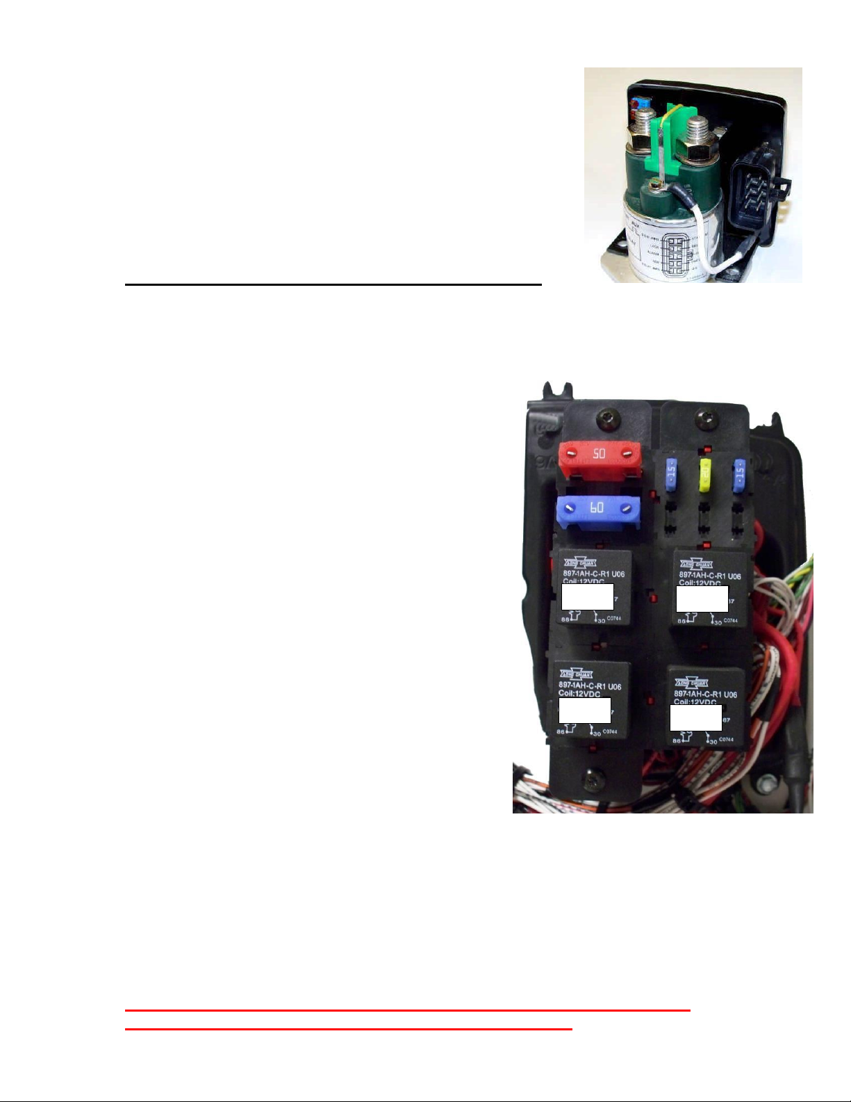
2. Compressor Fuse or Relay.
3. Compressor controller
connections.
4. Compressor controller board.
5. High pressure switch
6. Evaporator Sensor/Freeze
switch defective
7. Compressor thermal switch
8. Defective compressor
9. Blend door position.
10. Evaporator blower
11. Loss of charge (refrigerant
system not serviceable).
1. Clear any blockage from recirculation grill or louvers. Also
check condenser inlet and outlet for restriction (under
truck).
2. Check F1 fuse and PARKED MODE LS3 relay. See
appendix F and D
3. Confirm all wire harness plugs are connected.
4. Check Control PCB Assembly. See appendix I
5. Check pressure switch. See appendix E
6. Check freeze switch. See appendix G
7. Check thermal switch. See appendix H
8. Check power to compressor. See appendix I
9. Check blend door operation. See appendix M
10. Check Evaporator blower. See appendix K
11. If all tests check OK a loss of charge may have occurred.
Unit Cycles On And Off
1. Poor electrical connection.
2. Condenser fan inoperative.
3. Air flow blockage causing high
pressure or freeze condition.
1.
Check all electrical connections.
2.Check condenser fan. See appendix J
3.Check for restricted airflow under truck at condenser inlet
and outlet and at louvers and recirculation grill. Check
pressure switch and/or freeze switch. See appendix E and G
Unit Blows Cold Air, But
Low Airflow
1. Check all duct work
connections.
2. Air flow restricted
3. Evaporator Blower motor
inoperative.
1. Make sure all ducts are connected, sealed and secure.
2. Check for airflow at louvers and recirculation grill.
3. Check evaporator blower motor. See appendix K
Unit Runs Correctly, But
Less Than Expected Run
Time
1. Ground terminal(s).
2. AUX batteries weak or not
charged correctly.
3. Separator not functioning
correctly.
4. Trucks main batteries poor
condition
5. High amperage draw
6. Defective Outside air
temperature sensor.
1. Inspect and tighten ALL connections.
2. Check AUX batteries for condition and state of charge.
See appendix A
3. Check separator connections and operation. See
appendix B
4. Check Main truck batteries for condition and state of
charge. See appendix A
5. Use DC ammeter to check amps when running.
Excessive amperage could signal compressor or internal
component issue. Amperage ranges 40A to 75A
depending on conditions
6. Energy management will stop and amp usage will
increase.
7. See appendix O.
Unit is Noisy or Vibrates
1. Evaporator Blower motor.
2. Condenser fan motor.
3. Compressor mounting.
1. Check evaporator blower. See appendix K
2. Check condenser fan. See appendix J
3. Check rubber compressor mounts. See appendix L
Unit runs but does not blow
hot air
1. Heater power and ground
2. Heater fuse
3. Wiring harness
4. Heater enable signal
1. Check for power at the heater pins 1 & 2
2. Check heater fuse F3. See page 5.
3. Check wiring harness connectors and physical condition
4. Check for heater enable 12V at heater pin 7 from control
PCB assy, pin C15
NOTE: Heater diagnostics can be performed using Espar’s EDITH diagnostics lap top based program. You must have the ISO
cable adapter for the ParkSmart Hydronic heater. It is proprietary to Freightliner and other cable adapters will not interchange!

12
Appendix
A. Battery Condition and Performance:
Battery Voltage is critical for system operation. Special attention should be
given to both sets of batteries.
Attention: Poor quality truck batteries or a weak alternator will have a
Negative impact on Park Smart unit run time. Always maintain the best
possible batteries and charging system.
Standard alternator 270 Amp
.
Load test and maintain batteries as required by the manufacturer.
B. Separator
Check the voltage of the trucks main batteries on the separator (main) battery
terminal.
With the truck not running the truck battery Voltage should be under 13 Volts.
Anytime the truck main battery voltage is below 13.2 the separator contacts
will be open.
Start the truck. When a Voltage of 13.2 on the truck batteries is reached, the
separator contacts will close, and allow power to begin charging the AUX
batteries. You should see a voltage increase going into the AUX batteries.
Using a clamp on DC ammeter you will see the rate of charge going to the
batteries.
When this occurs, the separator is working correctly.
If the separator does not close or closes and does not allow charging to the
AUX batteries, replace the separator.
Please note: It is normal for the separator to change back and forth between
charging the truck bank of batteries and the AUX system bank of batteries,
especially in the first two hours. As the truck batteries regain charge the
separator will stay engaged for longer periods of time.

13
87
C. AUX Control Panel Testing: Attention! Conduct this test with ENGINE
OFF/ KEY OFF AND BRAKES SET!!!
First, check for proper voltage and signal at the ACU 26 pin connector. You
should have 12 volts across pins 4 (pos) and 5 (neg). You should also have 12
volts at pin 24 (wake up signal). Pushing the parked button switches the 12
volts at pin 24 to ground, signaling the Park Smart unit to operate.
During this test, you should not have 12 volts to pin 6 (ignition signal) and
you must have Can Bus connection for the unit to operate. 30
86
D. Relay Testing
With relay unplugged, confirm there is 12 VOLT
on the sockets where 85 and 30 relay terminals are
connected. 85
87
If you do not have 12 VOLT here check fuses, wiring
and battery connections.
Now, with relay unplugged, check across terminals 85 and 86 of the relay,
using an OHM meter. You should have an ohms value between 80 –100
ohms through the relay coil. If you do not, replace relay.
In Parked mode, as soon as you turn the AUX Control Panel blower switch
on and set the temperature control to cold and push the parked button,
terminals 86 on LS3 and LS4 relays become connected to ground internally on
the Control PCB Assembly pins D12 and D13. When this happens the relays
will pull in the contacts and allow voltage through the relays. You should now
have 12 VOLT passing through the relay on spade terminal 87 of the relay.
This provides power through fuses F1, F4 and F5, to the evaporator blower,
condenser fan and the compressor controlling section of the Control PCB
Assembly.
With relay plugged in: TURN THE UNIT ON IN PARKED MODE. If you do
not have 12 VOLT on terminal 87, check across terminals 85 (+) an 86 (-).
You should have 12 VOLT. If you have 12 VOLT here and do not have 12
VOLT on terminal 87 your relay is defective. The internal coil of the relay is
energized but the contacts are not closing.
(Continued on next page)

14
Replace the relay.
If you have 12 VOLT on terminal 87 and the compressor does not run you
could have a defective Control PCB Assembly or compressor. See testing
Control PCB Assembly. Appendix I.
E. Pressure Switch Testing: You must remove the top section of the ParkSmart
unit to access the switch.
The brazed switch (see photo page 7) is not removable. This switch is
normally closed. When the unit is off for a few minutes, unplug the 32 pin
connector on the PCB assembly and check across terminals D2 and D5, you
should always have continuity. If you do not, you may have a broken wire, bad
connection, hi pressure situation or defective switch. If the pressure, harness
and connections are ok, the unit will have to be replaced. Call Freightliner
Dealer
F. Check continuity across fuse body (fuse does not look blown)
NEVER INSTALL FUSE F6. THIS IS FOR PROGRAMMING ONLY AND IF
INSTALLED IT WILL DISABLE THE PARKSMART UNIT!
Remove fuse from fuse holder. Using a meter, check for continuity across the
fuse. You can check for voltage across the fuse using a dc volt meter.
G. Evaporator Sensor/Freeze Switch Testing: Location: Top of unit, behind the
evap coil, just inside the Cabinet base.
IF THE SENSOR OR CIRCUIT HAS A SHORT OR OPEN, the fault code
will be seen on J1939. IF THE SENSOR IS DEFECTIVE THE
COMPRESSOR WILL NOT OPERATE!
The freeze switch is a temperature sensor. To verify the condition you will need
a Volt/OHM meter.
If a freeze condition occurs, the unit will stop the compressor. If the freeze
condition leaves, the compressor will restart and the ParkSmart unit will
continue to run.
See chart page 19 for sensor test data.

15
H. Compressor Thermal Limit Switch: You must remove the top section of the
ParkSmart unit to access the switch.
This device is a normally closed switch. If the compressor gets too hot, the
thermal limit switch will open and the compressor will stop. Checking with a
meter you should always have continuity between the two terminals when it is
cool.
I. Control PCB Assembly:
Do not attempt to test the controller or compressor until you have
completely eliminated all other possibilities.
In parked mode, when you turn the Park Smart unit on, the compressor relay
LS 3 and blower/fan relay LS 4 will close. LS 3 will send 12 VOLT main
power from terminal 87, through the F 1 fuse, to the compressor controller
section of the control PCB assembly. LS 4 will send main power through it’s
terminal 87, through F 4 and F 5 fuses to the blower and fan. If all other
conditions are ok, such as the high pressure switch, freeze switch and the
compressor thermal limit switch, the compressor controller will then send
voltage out to the compressor.
Check for 12 VOLT from the F 1 fuse going to the PCB controller pin C 1.
Also check for unfused 12 volts at pin C3 (Aux Battery Sense). If Aux battery
voltage is below 11.3 the ParkSmart unit will not operate in parked mode.
Before condemning an internal component or unit, try operating the unit with
engine running.
If you have the correct voltage in you should have voltage out on the three
wires connected to the compressor. Disconnect the three wires ,RING
TERMINAL UNITS ONLY! from the compressor. You will have to remove
plastic cap from the top of compressor.
Using a volt meter check each wire, positive on (blue, orange or yellow)
negative to battery ground. If you do not have a 6 volt pulse voltage out on each
wire, replace the controller. Pulse voltage means the controller will cycle to
each colored wire. You should see the voltage appear and disappear
continuously.
Ring Terminal Units –Follow steps below also see pages 38 - 41
!!! Cluster Block units –see instructions page 34-37!!!

16
Reconnecting the three wires you must connect blue to A, orange to B, and
yellow to C.
If you do have a 6 volt pulse voltage out and the compressor does not run you
have a defective compressor.
For additional wiring diagrams see pages 21/22
For controller pin out table see page 23
J. Condenser Fan Motor Testing: First do a visual inspection of all blower
parts.
For condenser fan location see Freightliner ParkSmart documents.
Reconnect any wires or plugs you might have disconnected when removing the
cover. Turn the Parked Unit on, if you do not have 12 volt at the fan, check
fuse F5 And relay LS4. If you have 12 VOLT main power, check for the signal
voltage from pin C 7 (white wire). You should have zero voltage with unit off
and 1.6 to 2.6 volts unit on. If all voltages are correct, reconnect the plug. If the
fan does not run, it is defective, and needs to be replaced
Using a DC ammeter you can check the amperage draw of the blower. Normal
amps approx. 9.5 max.
Caution: If attempting to connect blower to an outside power source,
internal electronic components are sensitive to arcing or reverse polarity!
Damage will occur!!

17
K. Evaporator Blower Motor Testing: First do a visual inspection of all
blower parts.
For evaporator fan location see Freightliner ParkSmart documents.
Reconnect any wires or plugs you might have disconnected when removing the
cover. Turn the Parked Unit on and check for 12 VOLT at the unit side of the
wiring harness. If you do not have 12 volt, check fuse F4 and relay LS4. If
you have 12 VOLT main power, check for the signal voltage from pin C 13
(tan wire). You should have 10 volts on low speed and approx. 6 volts at high
speed. If all voltages are correct, reconnect the plug. If fan does not run, it is
defective, and needs to be replaced.
Using a DC ammeter you can check the amperage draw of the blower. Normal
amps approx. 10 on high
Caution: If attempting to connect blower to an outside power source,
internal electronic components are sensitive to arcing or reverse polarity!
Damage will occur!!
L. Compressor Rubber Mounts:
Visual inspection of the compressor rubber mounts may be necessary if
excessive vibration is present. Check for loose mounting nuts. If mounting nuts
and captive studs are ok, vibration could be from the internal part of the
compressor. If so call your Freightliner dealer.
M. Blend Door Actuator: For blend door location see Freightliner ParkSmart
documents
Physical inspection can be seen through the top of the unit by removing the
fuse panel and evaporator blower.
This actuator motor drives the blend door. Each time the unit is powered up the
door sets to full cold. Removing the F 2 fuse will reset the unit and the blend
door.
When in the heat mode the blend door will direct recycled air through the
heater core as directed by the Aux. Control Panel in order to maintain a preset
temperature. The Espar Hydronic coolant heater will provide a constant flow
(Continued on next page)

18
of heated coolant through the heated core for internal bunk heat as well as
engine heat.
You cannot bench test this actuator.
Check for 12 volts at pin 2 on the actuator, this is power from pin C8 on the
Control PCB Assembly. Use a common ground to check this voltage. With
unit operating, phases A, B, C and D are switched to ground in a sequence.
With the door in a stationary position check for 12 volts, you should have 12
volts on each phase. When the door is being positioned, these phases will be
switched to ground. The voltage will be near zero on a switching phase.
N. Sleeper Temperature Sensor: Location see Freightliner ParkSmart
documents
This sensor monitors the sleeper internal temperature. See chart page 18 for
testing data.
If this sensor fails, the unit will default to 72 degrees.
O. Outside Air Temperature Sensor: Location see Freightliner ParkSmart
documents
This sensor monitors the ambient air temperature. See chart page 18 for testing
data.
If this sensor fails, the power management system stops and although the unit
will still operate, the total run time of the battery pack will be reduced.

19
Evaporator Sensor Resistance Chart
A
B
C
D
1
Evaporator Sensor
2
3
Temp(ºF)
Temp (ºC)
Resistance
(nominal)
Voltage
(nominal)
4
-40.0
-40.0
92757.0
4.554
5
-31.0
-35.0
66870.0
4.402
6
-22.0
-30.0
48790.0
4.215
7
-13.0
-25.0
35937.0
3.991
8
-4.0
-20.0
26757.0
3.732
9
5.0
-15.0
20103.0
3.443
10
14.0
-10.0
15252.0
3.133
11
23.0
-5.0
11664.0
2.81
12
32.0
0.0
9000.0
2.488
13
41.0
5.0
6998.0
2.175
14
50.0
10.0
5485.0
1.882
15
59.0
15.0
4330.0
1.613
16
68.0
20.0
3443.0
1.374
17
77.0
25.0
2757.0
1.164
18
86.0
30.0
2221.0
0.982
19
95.0
35.0
1800.0
0.826
20
104.0
40.0
1468.0
0.695
21
113.0
45.0
1204.0
0.585
22
122.0
50.0
993.2
0.493
23
131.0
55.0
823.2
0.415
24
140.0
60.0
685.8
0.351
25
149.0
65.0
574.2
0.297
26
158.0
70.0
482.9
0.252
27
167.0
75.0
408.3
0.215
28
176.0
80.0
346.8
0.184
29
185.0
85.0
295.6
0.157

20
Sleeper & Ambient Air Sensor Resistance Chart
A
B
C
D
1
Sleeper, Condenser Air Inlet Temperature Sensor
2
3
Temp(ºF)
Temp (ºC)
Resistance
(nominal)
Voltage
(nominal)
4
-40.0
-40.0
336500.0
4.86
5
-31.0
-35.0
242589.0
4.80
6
-22.0
-30.0
177000.0
4.73
7
-13.0
-25.0
130370.0
4.64
8
-4.0
-20.0
97070.0
4.53
9
5.0
-15.0
72929.0
4.40
10
14.0
-10.0
55330.0
4.24
11
23.0
-5.0
42315.0
4.04
12
32.0
0.0
32650.0
3.83
13
41.0
5.0
25388.0
3.59
14
50.0
10.0
19900.0
3.33
15
59.0
15.0
15708.0
3.06
16
68.0
20.0
12490.0
2.78
17
77.0
25.0
10000.0
2.50
18
86.0
30.0
8057.0
2.23
19
95.0
35.0
6531.0
1.98
20
104.0
40.0
5327.0
1.74
21
113.0
45.0
4369.0
1.52
22
122.0
50.0
3603.0
1.32
23
131.0
55.0
2986.0
1.15
24
140.0
60.0
2488.0
1.00
25
149.0
65.0
2083.0
0.86
26
158.0
70.0
1752.0
0.75
27
167.0
75.0
1481.0
0.65
28
176.0
80.0
1258.0
0.56

21
Table of contents
Other freightliner Automobile Accessories manuals
Popular Automobile Accessories manuals by other brands

EUFAB
EUFAB 16256 operating instructions

Car Shades
Car Shades FIAT 500L MPW 5DR installation manual

TechniSat
TechniSat DIGICAR 2 BT quick start guide

Prorack
Prorack K1047 manual

Whelen Engineering Company
Whelen Engineering Company 73 Series installation guide

Blue Ox
Blue Ox AVENTA II Operator and installation manual